
Abstract
This study employs polyvinyl alcohol (PVA) fibers and silane coupling agent (SCA) to augment rubberized concrete mechanical prowess. A multiscale investigation delves into the synergistic enhancement mechanism of SCA on the interfaces of PVA/cement and rubber/cement, considering macroscopic mechanical properties, microscopic structural characteristics, and nanoscale interface interactions. Initially, fundamental mechanical performance tests reveal a notable enhancement in compressive and flexural strength with the inclusion of SCA and PVA fibers in rubberized concrete. Subsequently, observations of corresponding composite concrete slices are conducted using scanning electron microscopy (SEM), X-ray diffraction (XRD), and Fourier-transform infrared spectroscopy (FT-IR). The results manifest gel and polymer filling interface gaps, with SCA fostering a tighter amalgamation of the two interfaces, effectively rectifying interface defects and elucidating its bonding effects at the microscopic interface. Molecular dynamics (MD) modeling and simulation analyses of PVA/C-S-H and rubber/C-S-H, pre- and post-SCA modification, demonstrate that SCA mitigates interface effects, reinforcing hydrogen bonding, van der Waals interactions, Ca-H coordination bonds, and stability. This augmentation enhances interface adhesion energy, fortifying the weak interface bonding between PVA fibers, rubber, and inorganic silicate (C-S-H). Ultimately, portal frame experiments substantiate that incorporating fiber rubberized concrete into structures not only fails to diminish but marginally enhances the load-bearing capacity of the framework. This research furnishes concrete and innovative solutions for sustainable development while providing a valuable reference for the future application of PVA fiber rubberized concrete materials in practical engineering endeavors.
Keywords
Introduction
In recent years, global attention has increasingly focused on the atmospheric pollution generated by the cement industry. Studies indicate that approximately one ton of carbon dioxide is released for every ton of cement produced, with the cement industry contributing to about 7% of the world’s total carbon dioxide emissions. 1 Consequently, reducing cement consumption and exploring novel construction materials are of paramount importance for the environment. Rubberized concrete, an environmentally friendly building material created by incorporating waste rubber particles into ordinary concrete, has gained prominence. It enhances the impact resistance, impermeability, thermal and acoustic insulation properties, as well as fatigue resistance of ordinary concrete.2,3 Simultaneously, it addresses the issues of land occupation and environmental pollution associated with discarded tire rubber, presenting broad prospects for applications in multiple domains.4,5 However, rubberized concrete, being a novel composite material composed of rigid and elastic components, undergoes variations in its internal microstructure and damage physics. This leads to the formation of numerous weak interface transition zones, constraining its widespread adoption and application in structural engineering.6,7 Concurrently, certain mechanical properties exhibit a weakening trend with the incorporation of waste rubber, prompting current research to focus on improving the resilience of concrete while minimizing strength losses when utilizing discarded rubber. 8
Within the cement matrix, PVA fibers demonstrate commendable dispersibility and bonding capabilities. The introduction of PVA fibers into rubberized concrete holds promise in ameliorating debilitated interfacial transition zones, mitigating the declining trend in the strength of rubberized concrete, fortifying the adhesive capacity in the interfacial region, thereby effectively rectifying the performance deficiencies inherent in rubberized concrete.9,10 Extensive experimentation and finite element simulations elucidate that fiber incorporation can curb the formation and propagation of internal pores and cracks within the concrete, markedly enhancing its toughness, ductility, impact resistance, and durability.11–14 Consequently, researchers propose the amalgamation of fibers and rubber into concrete to attain specific properties while concurrently reducing costs, maximizing economic benefits.15,16 Yong Feng 17 conducts mechanical tests to assess the performance of concrete with varying PVA-rubber content, establishing a detailed numerical model for PVA-rubber/concrete composites. Simulating the entire process from intact to damaged to cracked states for different PVA-rubber content concrete, he validates the correctness of the finite element micromechanical model, providing a theoretical foundation for the structural numerical simulation analysis of such concrete.
The novel composite material formed by rubber particles and PVA fibers may harbor numerous weak interfacial transition zones within its structure. Such weak interfaces often prematurely lead to the degradation of composite materials. 18 Notably, interfaces between rubber and the cement matrix, as well as between PVA and the cement matrix, are prone to inadequate bonding, establishing weak interfaces as a primary cause for early specimen failure. To enhance adhesion and compatibility between various concrete materials, silane coupling agents (SCA) can be employed. SCAs hydrolyze groups, forming chemical bonds (coupling) between inorganic and organic materials. This process is crucial for improving the interface bonding quality among silicon-based materials and enhancing the mechanical performance of composite cementitious systems. 19 For instance, Ao Zhou et al. 20 discovered that SCA can elevate the bond strength of fiber-cement composites, consequently enhancing compressive and tensile strength of specimens. Simultaneously, PVA fibers enhance the performance of rubberized concrete, with a slight reduction in compressive strength of rubber particles and varying degrees of improvement in flexural and shear strength. Weijian Wang 21 highlighted the suboptimal bonding between PVA fibers and rubber particles, addressing this concern in PVA/rubber concrete interfaces by incorporating the SCA-KH560 modifier. Various tests, including compression, shear, fracture, SEM, and FTIR, were conducted to assess its performance. The study results demonstrate that the KH560 modifier effectively resolves the issue of poor adhesion in PVA-rubber concrete interfaces.
While previous experiments demonstrated the synergistic effect of SCA and PVA in rubberized cement, most interface studies have been confined to the macroscopic level, with limited insights into the molecular-level mechanisms. To gain a more profound understanding of the enhancement mechanisms, a more refined direction of research is required. Molecular Dynamics (MD) simulation, an experimental condition-approximating molecular modeling method, allows the visualization of experimental patterns at the atomic level, facilitating the exploration of modification mechanisms. It can complement experimental approaches, providing support for the study of novel composite materials.22–24 Hou et al. 25 employed molecular dynamics simulation to study the interface binding properties of graphene oxide and non-oxidized graphene-modified calcium silicate hydrate (C-S-H). Their research revealed a robust interaction between epoxy resin and graphene sheets, significantly enhancing the modified interface binding performance. Jiao Yu et al. used SCA and PVA fibers to study the reinforcing effects of rubber concrete respectively, and studied the strengthening mechanism of the interface between PVA and SCA and waste rubber/cement slurry through MD.26,27 Previous studies have shown that SCA and PVA fibers can enhance the mechanical properties of rubber concrete, but the synergistic reinforcing effects of SCA and PVA were not considered in the MD study. In addition, the synergistic mechanism between the two is still unclear.
To facilitate the practical application of fiber-reinforced rubberized concrete in engineering, this study comprehensively explores the reinforcing effects of SCA and PVA fibers on rubberized concrete from macroscopic, microscopic, and molecular dynamics simulation perspectives, as illustrated in Figure 1. Firstly, at the macroscopic level, SCA modification of both PVA fibers and rubber particles is undertaken, followed by mechanical performance testing of the composite concrete material. Secondly, at the microscopic scale, the interface structures between SCA-modified polymers and the cementitious material are characterized using scanning electron microscopy (SEM). The impact of chemical composition on reaction products is determined through X-ray diffraction (XRD) and Fourier-transform infrared spectroscopy (FTIR). Subsequently, at the molecular level, molecular dynamics software is employed to analyze the static interface structure and dynamic characteristics of SCA-modified PVA fiber-rubber concrete. Finally, experimental studies are conducted using a portal frame structure. From a macroscopic perspective, the application of modified PVA fiber-rubber concrete in reinforced concrete frame structures is explored through mechanical performance testing. This aids in determining its influence on structural load-bearing capacity, providing a reference for the future practical application of PVA fiber-rubber concrete materials in frame structure engineering. Multiscale analysis.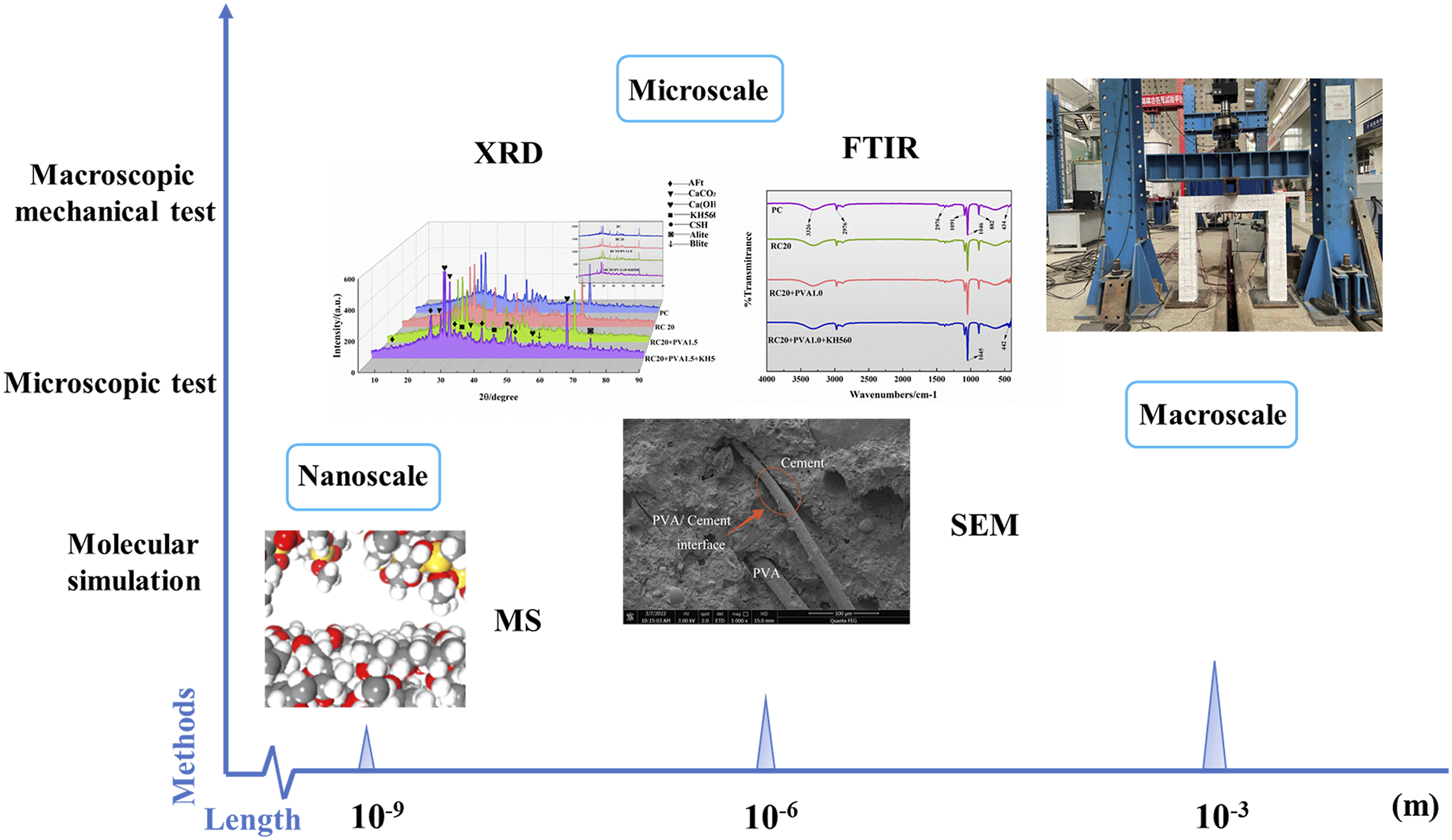
Methods
Main materials
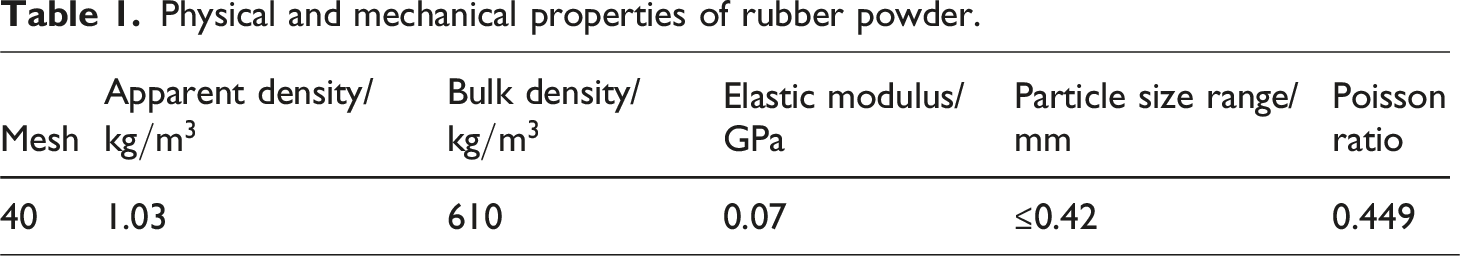
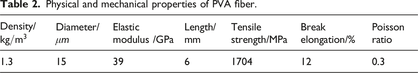
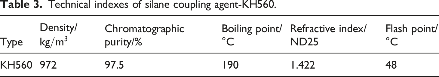
The Portland cement (PO42.5) employed in this research was sourced from China National Cement Co., Ltd., located in Hebei province. As delineated in Figure 2(a) and Table 1, the rubber utilized possessed a mesh size of 40, sieved through a screen with a diameter of 0.42 mm. The fineness modulus and specific gravity of the rubber were 2.8 and 1105 kg/m3, respectively. As depicted in Figure 2(b), the high-strength, high-modulus PVA fibers were supplied by Morning Banner Chemical Technology Co., Ltd., a subsidiary of China Limited Company, with their physical and mechanical properties elucidated in Table 2. The silane coupling agent (KH560), employed for surface modification of the polymer, as illustrated in Figure 2(c), was procured from Genesis Chemical Additives Co., Ltd., based in Nanjing, China. Detailed technical specifications are available in Table 3. Main materials for the experiment. Physical and mechanical properties of rubber powder. Physical and mechanical properties of PVA fiber. Technical indexes of silane coupling agent-KH560.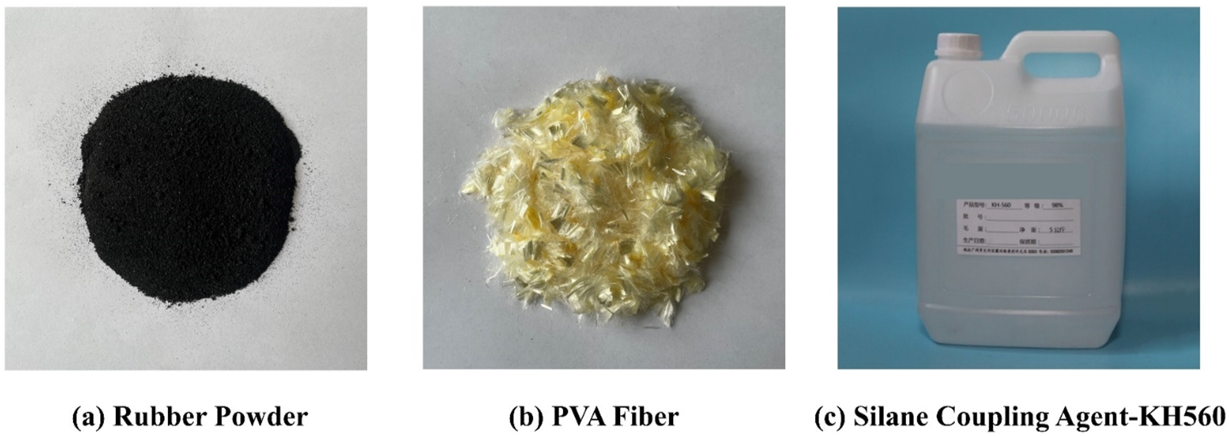
Treatment method and mechanism
In this work, the silicon coupling agent KH560 was selected as the modifier for PVA fibers and rubber powder. The molecular structure of KH560 contains active epoxy groups, which can undergo hydrolysis reactions in ethanol and water mixtures, forming Si-OH and -OH bonds. Post-treatment, the surfaces of rubber powder and PVA fibers exhibit numerous -OH bonds, while cement hydration products also contain -OH bonds and Ca(OH)2. This enables the Si-OH groups in KH560 to condense with the -OH groups in the hydrated products to form Si-O-Ca bonds, as shown in the Figure 3. Such bonds serve to enhance van der Waals interactions at the interface, while hydrogen bonds between hydroxyl groups further augment interface adhesion. SCA molecular formula and its change process.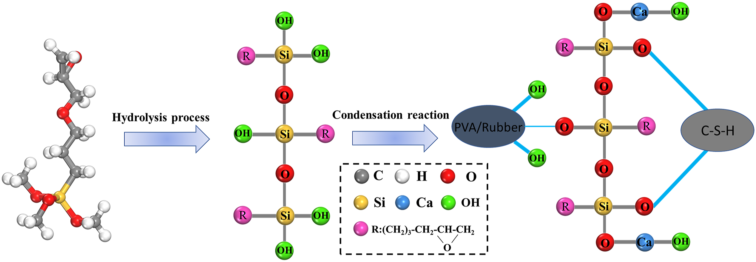
Initially, undergo treatment of PVA fibers and rubber powder by immersing them in anhydrous ethanol for 12 h to eliminate surface residues, followed by air-drying to a constant weight post-rinsing. Subsequently, formulate the agents for surface treatment of fibers and rubber. Deionized water and ethanol were mixed at a volume ratio of 19:1. In this process, a specified mass of the silicon coupling agent KH560 is incorporated. The addition of inert anhydrous ethanol aims to enhance the uniformity of the modifier, fibers, and rubber effects.
Finally, slowly pour the prepared coupling agent into the container containing rubber powder and PVA fibers. After stirring evenly, perform ultrasonic dispersion for 15 min to facilitate complete reaction. Subsequently, stir with a magnetic stirrer at 20°C for 10 min, the n heat the magnetic stirrer to 75°C at a rate of 1.5°C/minute and continue stirring for 10 min. After allowing it to stand at 20°C for 6 h, filter and cool to room temperature. Then, rinse with deionized water and dry it to constant weight in a drying oven at 40°C, completing the surface modification of fibers and rubber. The entire process is depicted in Figure 4. PVA fiber and rubber powder treatment process.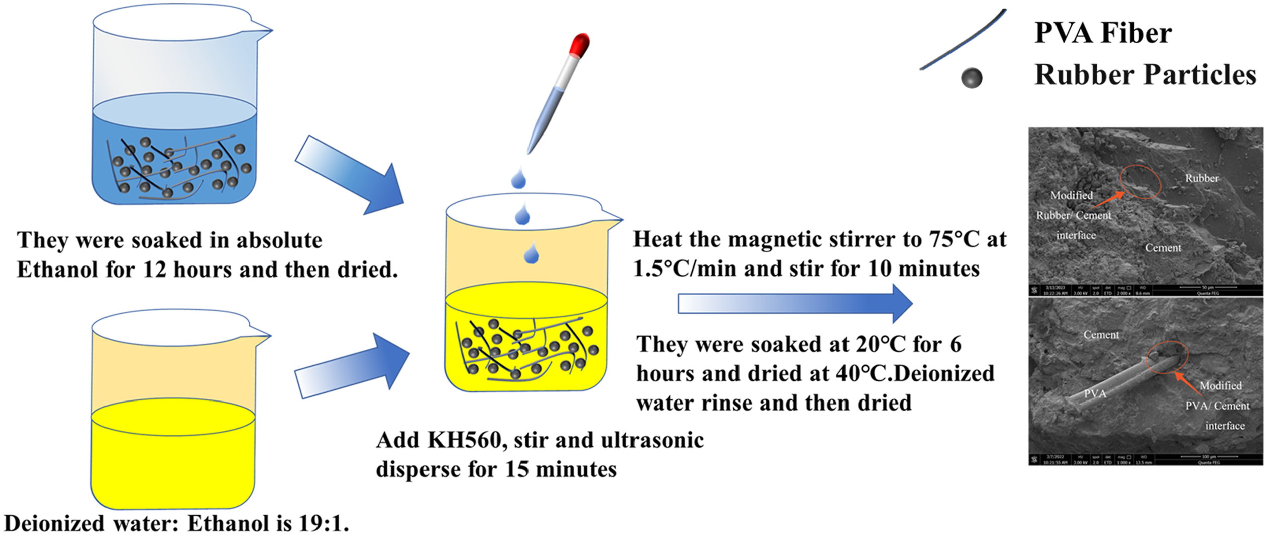
Experiment method
Mechanical performance testing
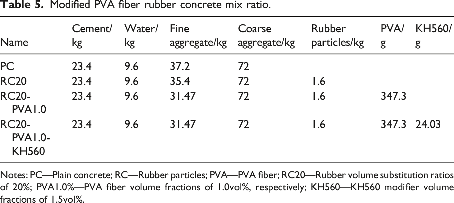
Modified PVA fiber rubber concrete mix ratio.
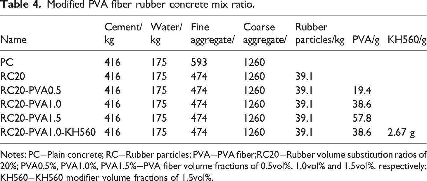
Notes: PC−Plain concrete; RC−Rubber particles; PVA−PVA fiber;RC20−Rubber volume substitution ratios of 20%; PVA0.5%, PVA1.0%, PVA1.5%−PVA fiber volume fractions of 0.5vol%, 1.0vol% and 1.5vol%, respectively; KH560−KH560 modifier volume fractions of 1.5vol%.
Following the “Concrete Physical Mechanics Performance Test Method” (GB/T50008-2019) standard, specimens are demolded 24 h after casting and cured for 28 days under standard conditions (20 ± 2°C, humidity ≥95%). Subsequently, compressive and flexural tests are conducted on the specimens. The compression test employs the Y250 digital electric stress-type direct shear apparatus, as illustrated in Figure 5(a). The flexural test utilizes the DKZ-5000 electric flexural testing machine, as depicted in Figure 5(b). Laboratory equipment: (a) pressure device; (b) breaking device.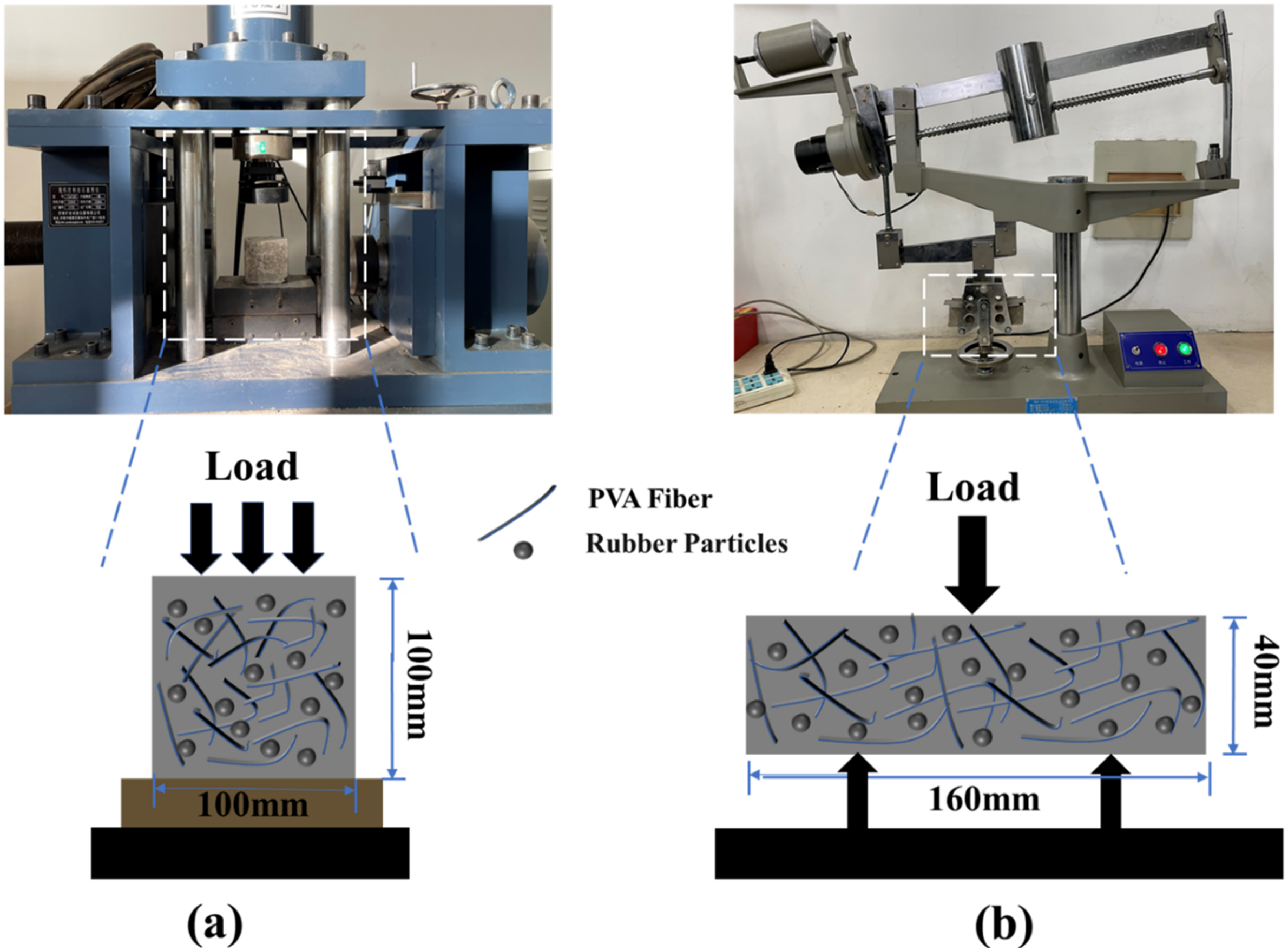
Microstructural features
After curing to the specified age, cut the specimens into 10 mm × 10 mm × 10 mm cubes. Terminate the hydration reaction by immersing them in anhydrous ethanol after polishing with 2000-grit sandpaper. Subsequently, dry the specimens for 24 h in a vacuum drying oven at 40°C, followed by air-blowing and filtering the samples. Fix the samples on a sample holder for vacuum gold coating. Utilize SEM equipment to observe the microstructure at the interface of rubber particles/cement and PVA fibers/cement matrix before and after modification. The equipment used is the Quanta FEG series scanning electron microscope produced by Beijing Zhuoteng Technology Co., Ltd.
Specimen preparation
Arain Muhammad Fahad et al. conducted an experimental study on the effect of PVA fibers on the properties of gel composites. Research shows that for high-performance fiber gel composites, the best results are obtained when the fiber content does not exceed 2%. 28 Drawing on the existing literature on the research on the mechanical properties of rubber concrete by SCA, a comprehensive analysis found that when the SCA content is 1.5% of the gel material, the mechanical properties of concrete are optimally improved.29,30 Therefore, in order to ensure the best effect, this article determines the maximum PVA fiber content and SCA content as 1.5% of the gel material.
Referencing the “General Concrete Mix Design Code,” establish the concrete mix ratio. In the design of specimens, the PVA content serves as the primary research parameter. Plain concrete (PC) specimens are designed with a strength grade of C25 and a water-cement ratio of 0.42. Rubber particles are incorporated by replacing fine aggregate in equal volume, denoted as RC for the rubber particle replacement ratio, fixed at 20%, designated as RC20. PVA and KH560 represent the content of PVA fibers and KH560, respectively. PVA0.5, PVA1.0, PVA1.5 denote PVA volume fractions of 0.5%, 1.0%, and 1.5%, respectively, while the KH560 replacement ratio remains fixed at 1.5%. Six sets (a-f) of PVA fiber rubber concrete mix ratios are designed, with specific compositions detailed in Table 4.
Chemical composition characteristics
X-ray diffraction (XRD)
To determine the physical phase composition and content of SCA and PVA fiber rubber composite materials, XRD analysis was performed on samples stored for 28 days. In this study, four parameters were chosen for comparison. Fragments of pure concrete (PC), RC20, RC20-PVA, and RC20-PVA-KH560 were immersed in anhydrous ethanol for 48 h to halt hydration. Subsequently, the soaked slices were ground into powder suitable for diffraction experiments, dried at 50°C for 24 h in a vacuum drying oven, and formed into flat specimens measuring 15 mm × 15 mm. Finally, the samples were analyzed using the Hangzhou Lemei Technology Co., Ltd. scientific Miniflex 600 desktop X-ray powder diffractometer.
Fourier transform infrared spectroscopy (FTIR) testing
The addition of SCA initiates a series of reactions with the hydration products of cement. The chemical interactions of SCA during the cement hydration process warrant further analysis. In this study, four parameters were selected for comparison. Damaged specimens of pure concrete (PC), RC20, RC20-PVA, and RC20-PVA-KH560 were individually ground into fine powders. Subsequently, they were dried in a vacuum for 24 h and observed using the PerkinElmer PE Spectrum Two infrared spectrometer. Further analysis is required to elucidate the chemical effects of SCA in the cement hydration process.
Interface model
To comprehend the synergistic enhancement mechanism of SCA-KH560 on the PVA/cement and Rubber/cement interfaces at the molecular scale, molecular dynamics simulations were conducted on two interface models with and without SCA. Four interface models were constructed using Molecular Dynamics (MD) software: C-S-H/PVA interface model, C-S-H/Rubber interface model, C-S-H/PVA/KH560 interface model, and C-S-H/Rubber/KH560 interface model, as illustrated in Figure 6. Four interface models (a) C-S-H/PVA (b) C-S-H/Rubber (c) C-S-H/PVA/KH560(d) C-S-H/Rubber/KH560.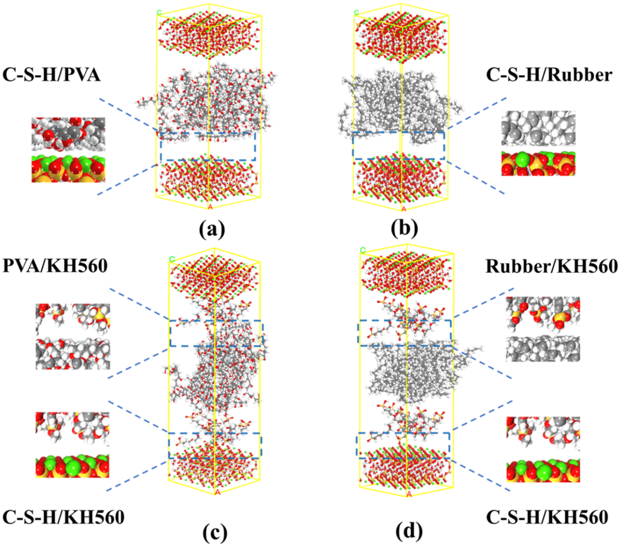
We first derived the initial model of 1.1 nm Tobermolite from the inorganic crystal library. The nanopore is then cut, expanded, and combined along the crystal face [0 0 1], and one side of the C-S-H substrate is about 11.0 ˚A thick (Figure 7(d)). Based on the predominant components of hydrocarbons in rubber raw materials and the widespread production and application of synthetic rubber surpassing natural rubber, a rubber model with a density of 1.93 kg/m³ was selected. The isotactic rubber (BR) chain consists of 8 isotactic rubber chains, with each isotactic rubber containing 16 monomers. The unit cell dimensions for the isotactic rubber are a = 20.20 Å, b = 20.20 Å, c = 18.28 Å, and τ = 90°. KH560 is an amorphous cell composed of molecules with a density of 1.047 g/cm³ and dimensions of a = 22.0 Å, b = 22.0 Å, c = 6.33 Å, and τ = 90°. This rubber model has been confirmed for use in MS software.
31
PVA fibers are derived from polyvinyl alcohol using specific advanced processing techniques. The PVA model can be obtained from previous data.
32
In this study, polyvinyl alcohol monomers (Figure 7(a)) were used to construct PVA polymer chains (Figure 7(b)), which were then used to build amorphous cells (Figure 7(c)). The degree of polymerization for the PVA used is 18, with an amorphous cell density of 1.29 g/cm³ and dimensions of a = 25.40 Å, b = 25.40 Å, c = 25.40 Å, and τ = 90°.The dimensions of the PVA amorphous crystalline cell need to be approximately the same as the C-S-H plane for the construction of the C-S-H/PVA interface model in the next step. A 5 Å vacuum layer was then added at the top to avoid unintended interactions along the z-direction due to periodic boundary conditions. Figure 7 illustrates the process of establishing the C-S-H and PVA interface models, with the cell parameters for the PVA/C-S-H interface model being a = 25.39 Å, b = 25.39 Å, c = 63.57 Å, α = 90°, β = 90°, and γ = 90° (Figure 7(e)). In the model, Rubber, KH560, and PVA do not have fixed surfaces; they can be optimized to better energy positions using the Force module in the software. Finally, since only the most crucial components of the materials are considered, many other components are fewer than the actual substances, which is reasonable for theoretical simulation. Modeling of the C-S-H/PVA interface.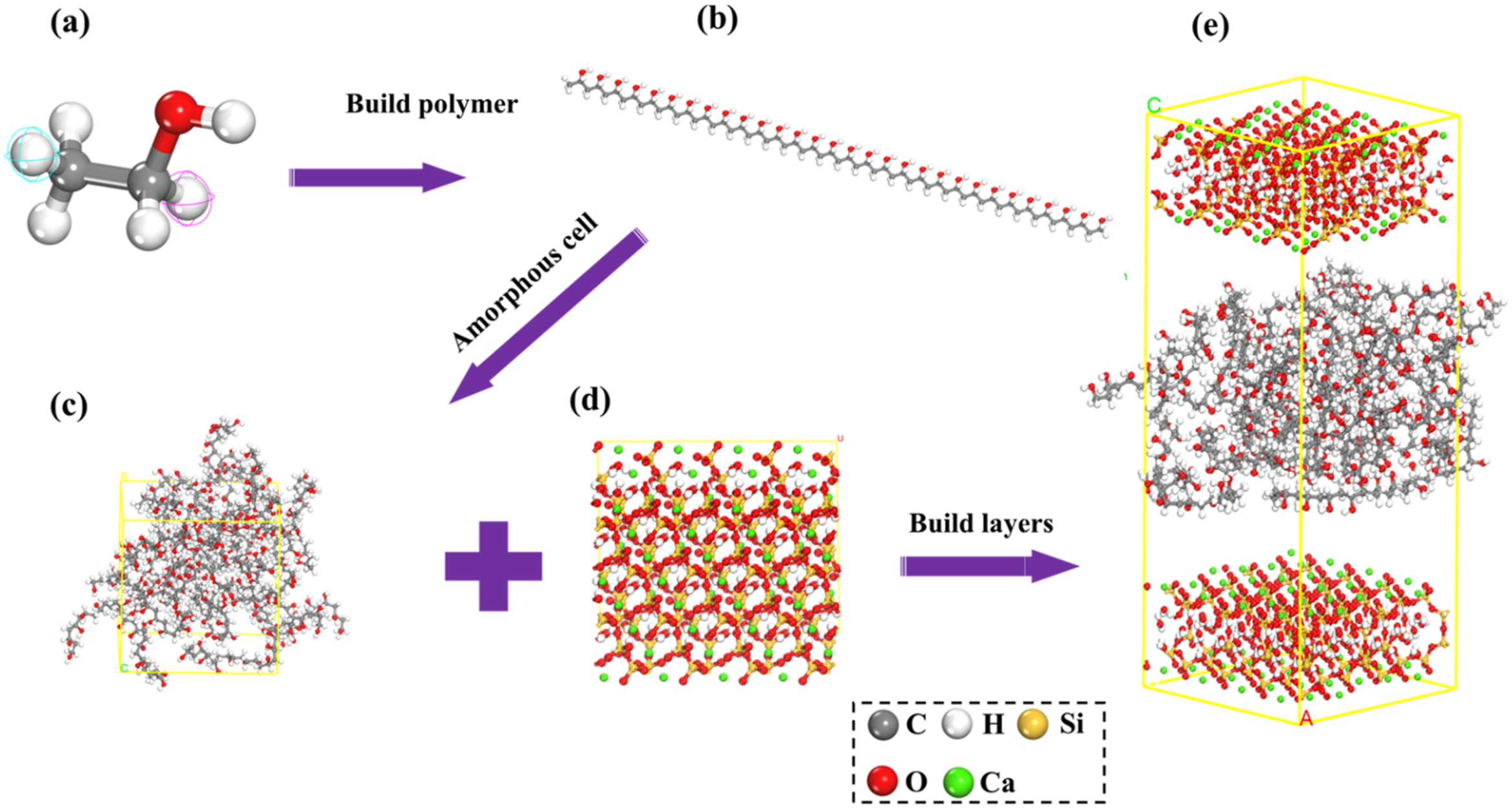
Force fields and simulation details
Before proceeding with subsequent analysis of its structural characteristics, it is essential to appropriately optimize and adjust the interface model. Firstly, existing experiments have demonstrated that the COMPASS force field aligns well with experimental data and can be applied to simulate cement hydration products, thereby possessing broader applicability.33,34 Using the Forcite module in Materials Studio software, the COMPASS force field was selected for simulation to conduct geometric optimization on the interface model. Equilibration runs were performed under isothermal-isobaric (NPT) conditions with a time step of 1 fs for 200 ps to allow the system to reach a more balanced state of stable density and volume at the target temperature from its initial state. Subsequently, another molecular dynamics experiment was conducted under constant volume and temperature (NVT) conditions with a time step of 1 fs and a total simulation time of 1 ns. This approach reduces the time required for the system to reach a stable state close to the real density, ultimately yielding trajectory files. Throughout this process, the simulation temperature was set to 300 K, with a charge of 0 for all particles, and the system temperature and pressure were controlled by Andersen and Berendsen methods, respectively. Temperature and density reached stable values, confirming sufficient relaxation time.
Results and discussion
Compression test analysis
Destroy form
The compressive failure characteristics of each specimen group, as depicted in Figure 8, reveal a notable departure from the reference group a (as shown in Figure 8(a)) when fibers and rubber powder are introduced. These specimens predominantly exhibit ductile failure. In contrast, specimens containing only rubber undergo a shear-type failure (as illustrated in Figure 8(b)), devoid of noticeable spalling. A singular transverse crack and a few microcracks parallel to the loading direction are observed. This phenomenon stems from the rubber particles’ capacity to withstand significant tensile deformation. As cracks propagate rapidly through the cement paste, they circumvent the movement of rubber particles, slowing down crack expansion and ameliorating the complete disintegration of the concrete. Compressive failure modes of different groups of specimens.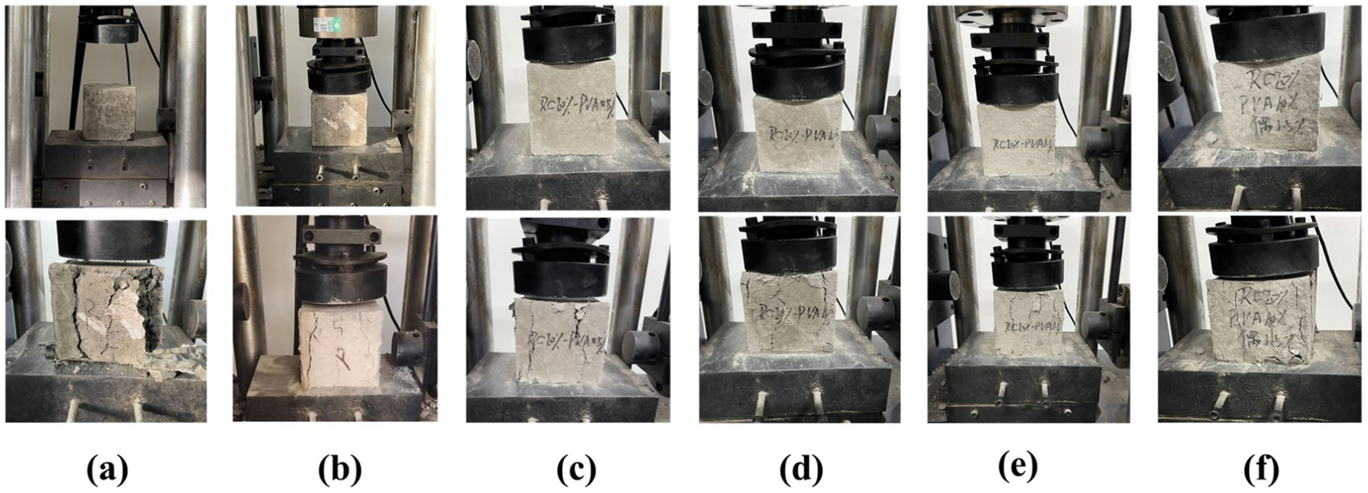
With an increase in fiber content, the width of penetrating cracks diminishes, and the number of surface microcracks increases. Under the ultimate load, specimens maintain relatively good integrity (as seen in Figure 8(c), (d), (e)), indicating that the addition of fibers can inhibit crack penetration and enhance the concrete’s resistance to brittle failure. Moreover, specimens infused with both fibers and rubber showcase superior improvements in deformation performance compared to those with either rubber or fibers alone. These specimens exhibit enhanced integrity, with no detachment of the cement paste at the specimen edges (as shown in Figure 8(f)).
Compressive strength
The concrete compressive strength test utilized non-standard specimens measuring 100 mm × 100 mm × 100 mm. Compression was conducted using the Y250 digital electric stress-controlled direct shear apparatus with displacement loading. To maintain a stable and uniform rate, a displacement control method was chosen with a velocity set at 1 mm/min.
The formula for calculating the compressive strength of the concrete cubes is given by: 
Where
Considering the use of non-standard specimens, the arithmetic average of the three replicates is multiplied by 0.95 to determine the compressive strength of the modified specimens, calculated to an accuracy of 0.01 MPa. The compressive strength of the specimens at 28 days is depicted in Figure 9. 28-day compressive strength of specimen.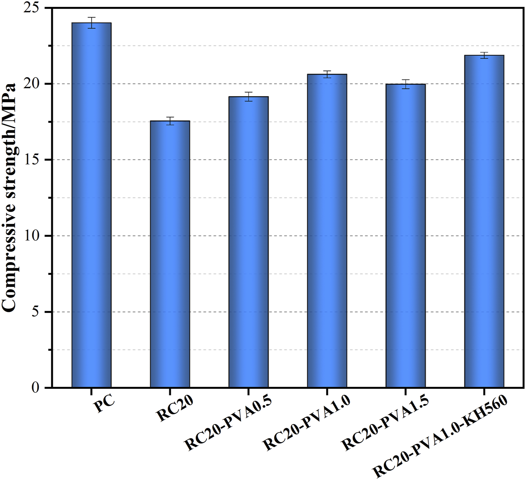
After 28 days, the compressive strength of the PC specimens was 24.02 MPa, while the RC20 specimens exhibited a strength of 17.56 MPa. Compared to RC20, the strengths of RC20-PVA0.5, RC20-PVA1.0, and RC20-PVA1.5 increased by 9.11%, 17.48%, and 13.78%, respectively. The addition of the modified agent, RC20-PVA1.0-KH560, increased the compressive strength by 24.6% compared to RC20. The compressive strength test results indicate that the introduction of an appropriate amount of PVA can enhance the compressive strength of rubberized concrete, and the KH560 modifier further improves the compressive strength of PVA fiber rubberized concrete.
The compressive strength of the RC20 specimens decreased by 26.89%. Two main reasons contribute to this decline: firstly, the inherent lower strength of rubber particles compared to other aggregates in concrete leads to the formation of local weak zones as they volumetrically replace sand in the concrete. With an increase in rubber particle content, the area of weak zones and defects rises, reducing the load-bearing capacity of the specimens. Secondly, rubber particles, being hydrophobic organic high-molecular-weight materials, tend to trap air, creating weak bonding surfaces between the rubber particles and the cementitious materials in the concrete mix. This simultaneously increases the porosity of the concrete specimens. As the rubber content rises, the number of weak bonding surfaces increases, resulting in a reduced load-bearing capacity of the concrete specimens.
Bending test analysis
Destroy form
The flexural failure morphology of specimens in each group, as depicted in Figure 10, reveals that the reference concrete specimen (a) exhibits a distinct brittle failure, promptly fracturing under the ultimate load. In contrast, specimens with the addition of fibers and rubber display a ductile failure. Following the initiation of cracks in the composite concrete, the specimens do not fracture immediately but rather develop cracks gradually from the bottom as the load increases. During the process of losing load-bearing capacity, some fibers may experience breakage and extraction. Additionally, as the content of fibers and rubber increases, the width of the fracture cracks decreases, accompanied by the emergence of secondary cracks, and the quantity of coarse aggregate fragments on the fracture surface decreases. Flexural failure modes of different groups of specimens.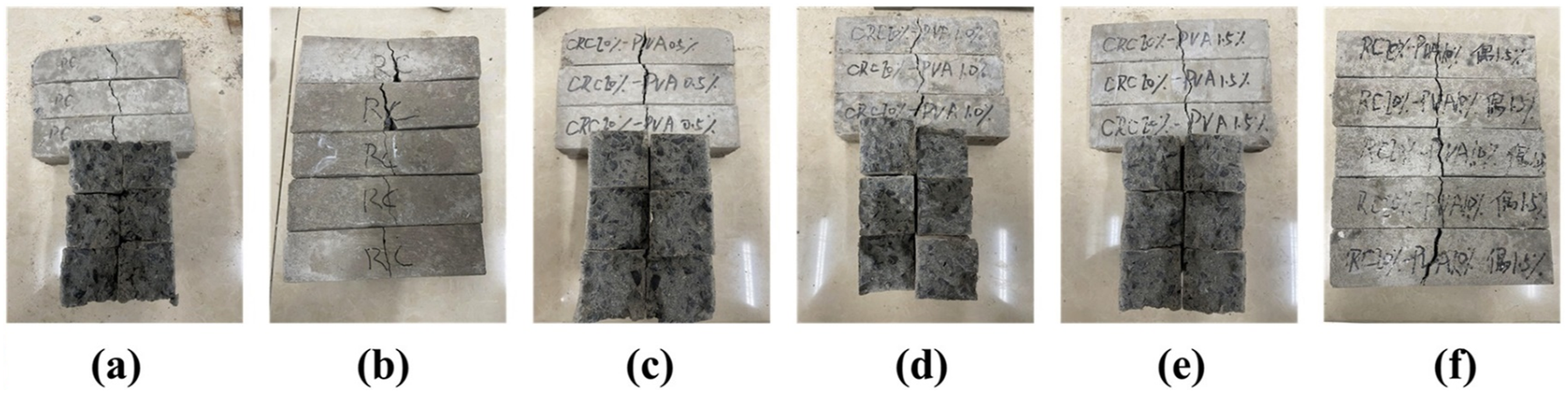
Flexural strength
The flexural testing of concrete involves non-standard specimens measuring 40 mm × 40 mm × 160 mm, employing a DKZ-5000 electric flexural testing machine through the central loading method for fracture. During the test, the testing machine must maintain a stable and uniform loading rate. Following the specimen’s failure, its strength at the point of fracture is recorded.
The formula for calculating the flexural strength is given by:
Due to the use of non-standard specimens, the arithmetic average of the maximum load values from three replicates is multiplied by 0.85 to determine the flexural strength of the modified specimens, with calculations accurate to 0.1 MPa. The flexural strength of the specimens at 28 days is illustrated in Figure 11. 28-day flexural strength of specimen.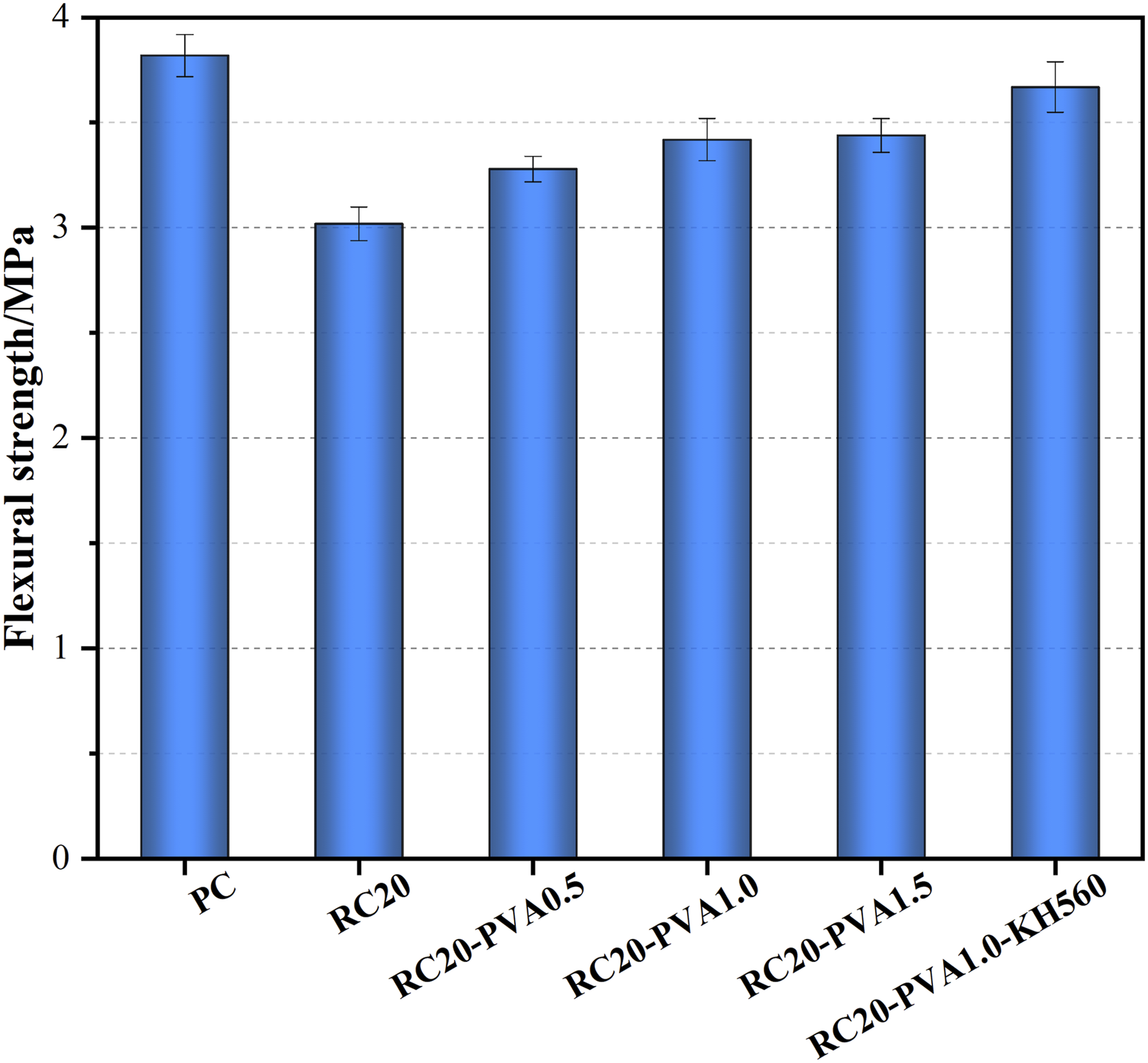
After 28 days, the flexural strength of the PC specimen is 3.82 MPa, while the RC20 specimen exhibits a strength of 3.02 MPa. Compared to RC20, the RC20-PVA0.5, RC20-PVA1.0, and RC20-PVA1.5 specimens show improvements of 8.61%, 13.25%, and 13.91%, respectively. Furthermore, the RC20-PVA1.0-KH560, incorporating a modifying agent, demonstrates an 21.52% increase in flexural strength compared to RC20. The flexural test results suggest that the addition of an appropriate amount of PVA enhances the flexural strength of rubberized concrete. This improvement is likely attributed to the bridging effect of PVA fibers, acting as reinforcing elements within the specimens. Moreover, the KH560 modifying agent further enhances the flexural strength of PVA fiber rubberized concrete.
Effect of microstructural characteristics
In Figure 12(a-b), significant gaps can be observed between PVA fibers and rubber particles and the cement matrix, indicating inadequate bonding between untreated rubber particles, PVA fibers, and the cement matrix, leading to the formation of a fragile interface. The presence of such brittle interfaces under stress can result in premature failure of specimens. However, the introduction of PVA fibers into rubber concrete greatly mitigates the brittleness of plain concrete. The random distribution of fibers largely eliminates the brittle behavior of plain concrete. In the later stages of failure of PVA-rubber/concrete specimens, PVA fibers provide three-dimensional reinforcement to resist internal tension, suppressing the rate of specimen failure and enhancing the strength of rubber concrete. Even after cracks penetrate the entire structure, failed components aggregate together through the fiber bridging effect. Upon incorporating 1.5% SCA, as shown in Figure 12(c-d), the PVA fibers and rubber particles treated with the modifier exhibit no significant cracks at the interface with the cement matrix, and the bonding is tight, forming a continuous and uniform interface. This indicates that SCA can enhance the adhesion of rubber particles and PVA fibers to the cement matrix, thereby improving the mechanical properties of PVA/rubber concrete. The SEM photos of the interface between PVA/cement paste and Rubber/cement paste before and after modification.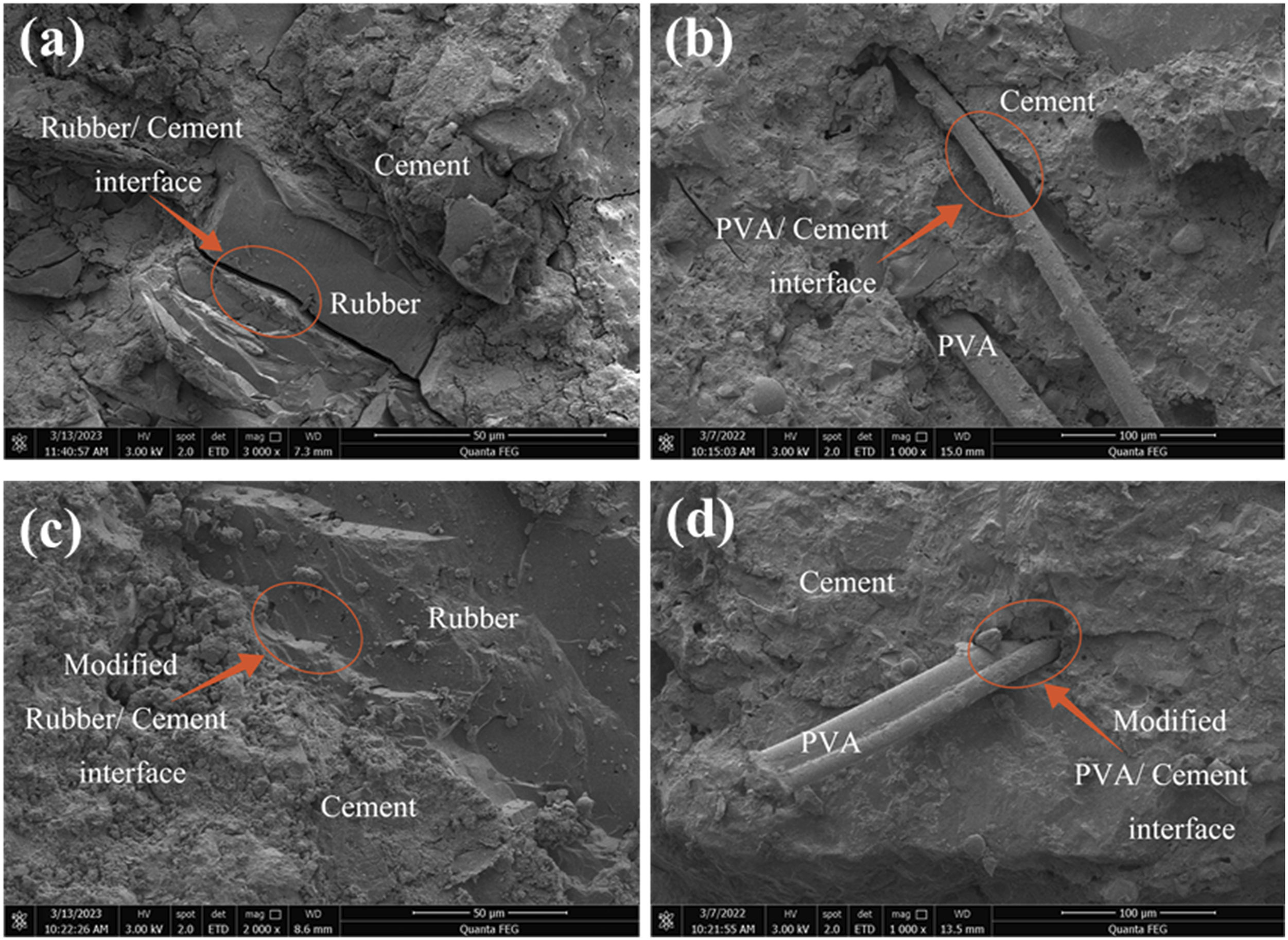
Effect of chemical composition characteristics
X-ray diffraction (XRD)
To verify the presence of gel at the interface, XRD analysis was conducted on the samples, and the results are shown in Figure 13. From the figure, it can be observed that the XRD results for RC20 and RC20-PVA1.0 are similar, indicating that the addition of fibers did not alter the chemical composition of the concrete. Therefore, the use of fibers alone cannot meet the requirements for enhancing the bonding between weak interfaces. Additionally, there is a short peak appearing between 28° and 33°, and before and after modification, the position and shape of the absorption peak are similar, with only changes in peak intensity. This indicates that SCA modification does not alter the type of hydration products but may affect the quantity and rate of hydration products. The change in Ca(OH)2 content is most notable. Unhydrated cement undergoes hydration reactions to generate Ca(OH)2, which further reacts chemically with CO2 in the air to form CaCO3, confirming the increase in CaCO3 content. Furthermore, in Figure 12, the peak intensity of the characteristic signal at 65° is significantly enhanced, indicating the generation of Ca(OH)2 during further hydration of unhydrated cement. In powders containing KH560 modifier, the characteristic peaks of hydrated minerals (Alite, Belite) are higher, indicating that KH560 delays the chemical reactions of cement. A short peak appears at 50°, possibly indicating low-crystallinity C-S-H gel, suggesting that the addition of KH560 increases the quantity of C-S-H gel, thereby increasing interface density. X-ray diffraction patterns of specimens with different fit ratios.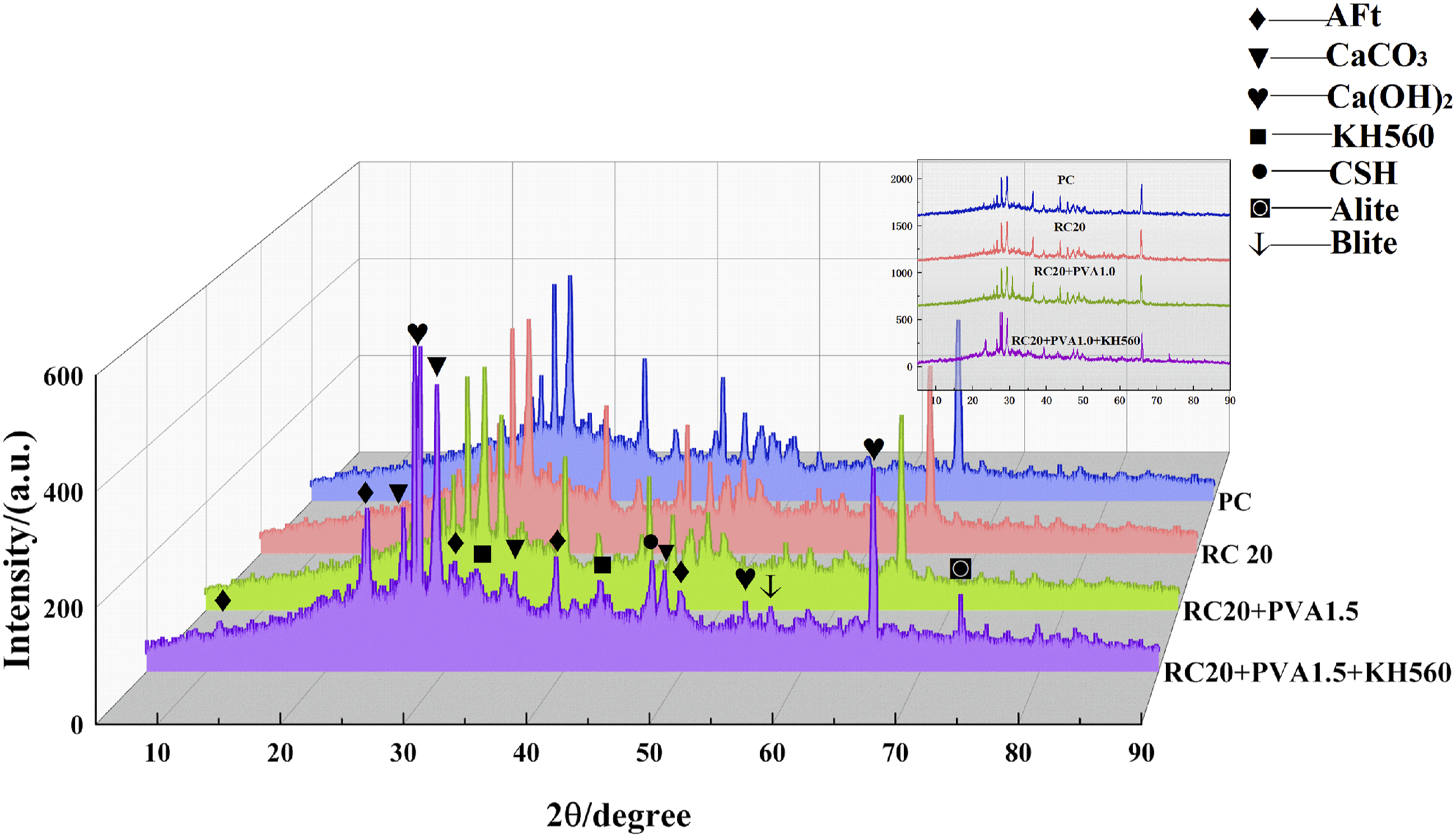
Fourier transform infrared spectroscopy (FTIR)
From Figure 14, it is evident that there are minor characteristic peaks in the infrared spectra after the addition of KH560 modifier. However, the overall positions of the characteristic peaks are roughly similar to those of the PC’s infrared spectrum. This indicates that no chemical reactions occur among SCA, PVA, and rubber upon addition, further emphasizing that fiber alone cannot meet the requirements for enhancing the bond between the gel and cement. It is noteworthy that the absorption peak at 882 Infrared spectrum of the specimen with and without SCA.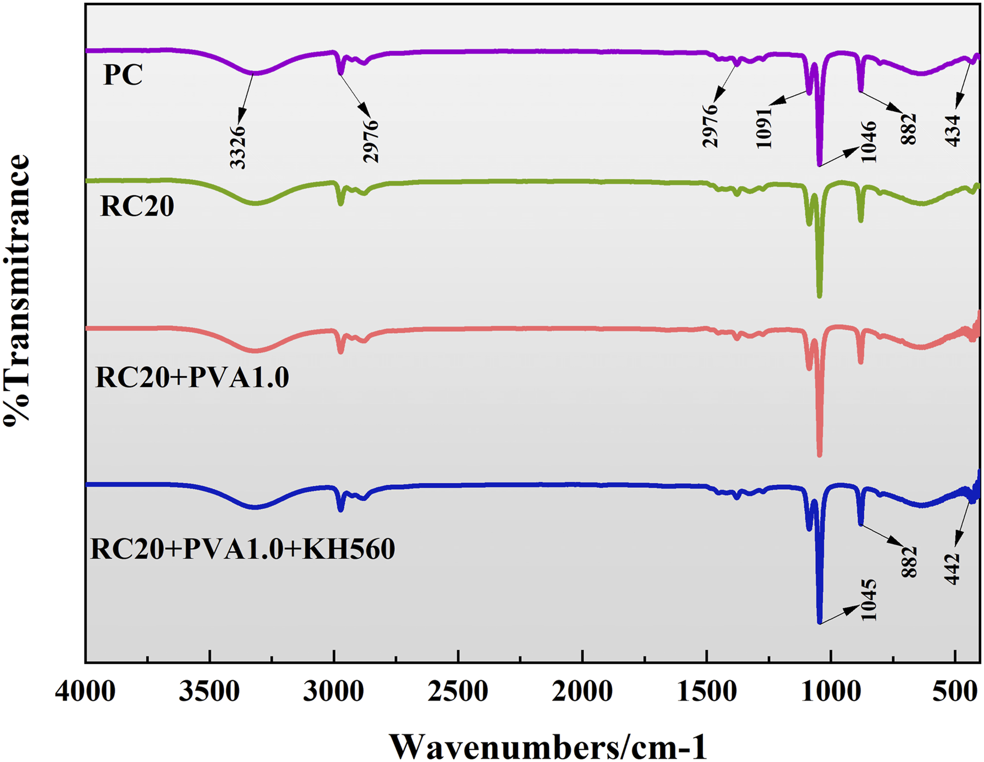
Analysis of molecular simulation results
Interfacial interaction energy
Interactions energies can serve as indicators of whether two phases exhibit mutual attraction or repulsion. A negative interaction energy signifies mutual attraction among distinct components. Defining interaction energy as the negative of binding energy (Ebind), namely Einter = -Ebind, the binding energy quantifies the magnitude of interactions between different components, influencing the overall stability of the system. Utilizing equation (1), the interlayer interaction energy (Einteraction) is calculated.
35

As illustrated in Figure 15, this study employs the Force module to individually calculate the binding energies of C-S-H/KH560, Rubber/KH560, PVA/KH560, C-S-H/PVA, and C-S-H/Rubber. It is evident that the binding energies involving KH560 with CSH, Rubber, and PVA exhibit relatively high absolute values, signifying that the introduction of SCA plays a pivotal role in enhancing interfacial interactions, crucially impacting the improvement of concrete strength. Interaction of C-S-H/KH560, Rubber/KH560, PVA/KH560, C-S-H/PVA, C-S-H/Rubber interfaces.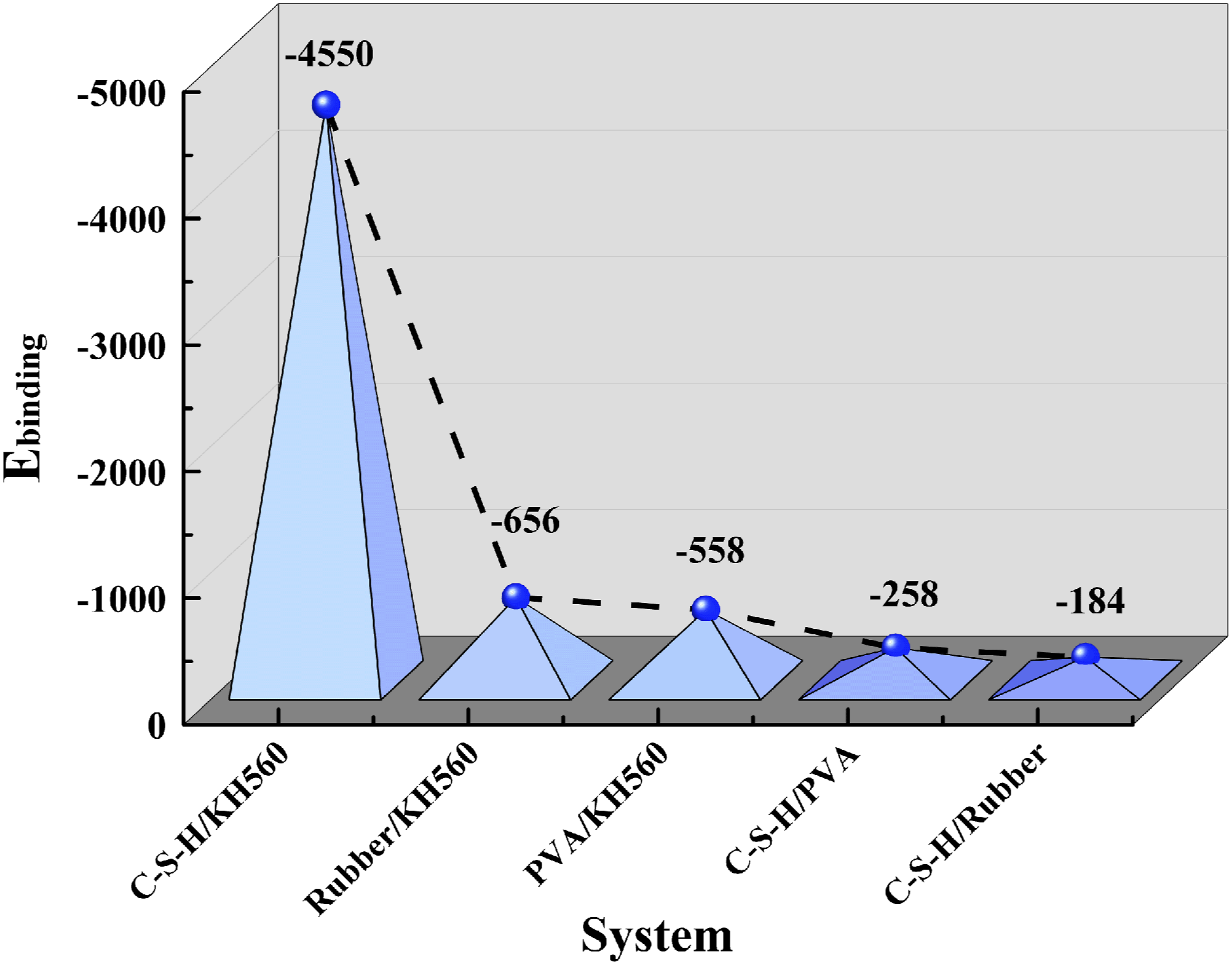
Radial distribution function
The Radial Distribution Function (RDF) encapsulates the essence of interfacial interactions. Also known as the pair correlation function, RDF allows for the analysis of interparticle relationships and microscopic distribution.
36
It unveils the interface binding mechanisms between Rubber/C-S-H, PVA/C-S-H, and the interface interaction between Rubber and PVA based on the spatial correlation of atoms within the model. This can be computed using the following equation (4).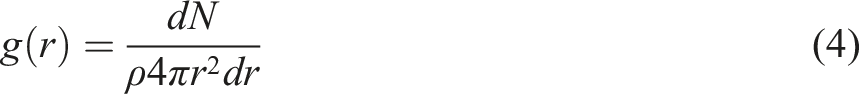
Utilizing the Force module, RDF for the four distinct systems was calculated. From Figure 16(a)–(d), it is evident that the predominant mode of interface interaction is van der Waals (vdW) interaction. Peaks corresponding to (a) RDF of 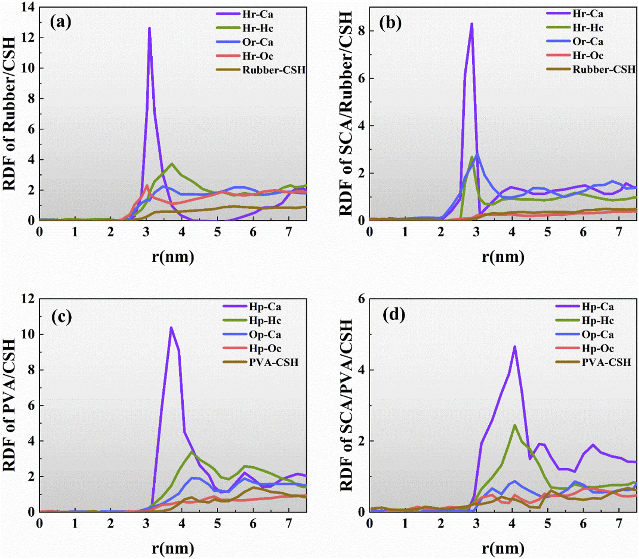
Root mean square displacement
The Mean Squared Displacement (MSD) refers to the average of the squared displacements of particles. In molecular dynamics, it serves as a metric to assess the motion characteristics of atoms.38,39 The slope of the MSD curve corresponds to the molecular diffusion coefficient, with a steeper slope indicating a larger diffusion coefficient. This can be calculated using the formula mentioned in the literature.
The computed results for the Mean Squared Displacement (MSD) values of Rubber/C-S-H, PVA/C-S-H, SCA/Rubber/C-S-H, and SCA/PVA/C-S-H are depicted in the Figure 17. From the graph, it is evident that the MSD values for Rubber and PVA are higher than that of C-S-H, indicating that C-S-H exhibits better stability compared to Rubber and PVA. Additionally, among these four systems, the MSD curves for the hydrogen atoms of Rubber and PVA are notably higher than those for other atoms, suggesting increased activity of H atoms at the interface. In contrast, Ca and O in C-S-H maintain relatively lower MSD values, further validating the stability of the C-S-H structure. The mean square displacements of (a) 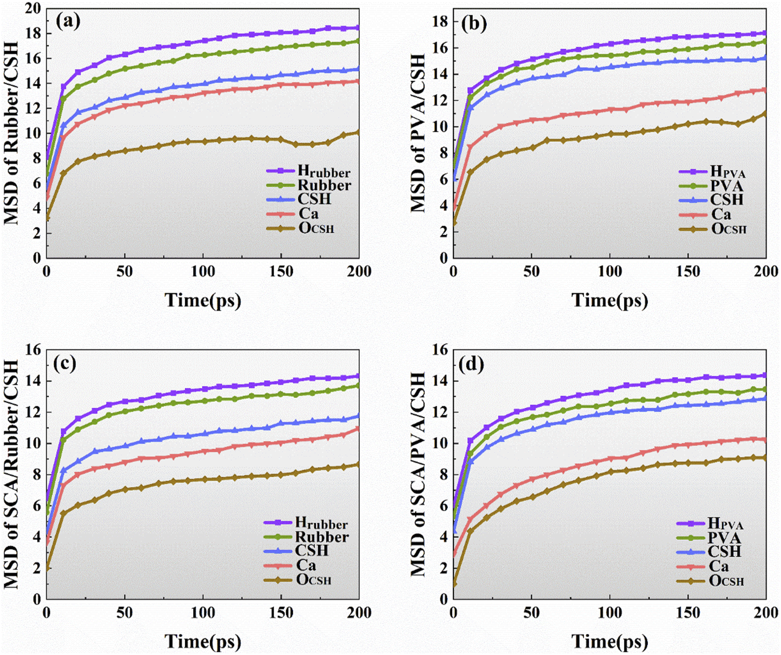
Noteworthy is the observation that in Figure 17(c) and (d), the MSD values exhibit varying degrees of reduction compared to the unmodified system before SCA addition. However, the order of atomic MSD values remains unchanged. This implies that the addition of SCA may not impact the relative stability of the system but rather restrains the free movement of H, Ca, and O within the channels. Simultaneously, it reinforces hydrogen bond interactions, leading to a more stable association between Rubber, PVA, and the C-S-H interface, thereby enhancing the overall performance of concrete.
Relative concentrations
In molecular dynamics, relative concentration is employed to assess the spatial positions of key molecules in interface models and characterize molecular states. It reflects the distribution of atomic density along a specific direction, as documented in the literature. Considering the constraints of modeling direction and periodic boundary conditions, this simulation exclusively analyzes concentration along the Z direction. The calculation involves partitioning the model into several boxes along the Z direction and counting the relevant atoms. Relative concentration can be computed using equation (6).
40

When calculating the distribution of relative concentration, crucial elements are selected to represent different systems. The results for the four systems are depicted in the Figure 18. It is evident from the graph that Si and Relative concentrations of Si, H, and C elements in the (a) Rubber/C-S-H system, (b) SCA/Rubber/C-S-H system, (c) PVA/C-S-H system, (d) SCA/PVA/C-S-H system. (subscripts w, Si, r, p, and s represent water molecular system, C-S-H system, Rubber system, PVA system, and SCA system respectively).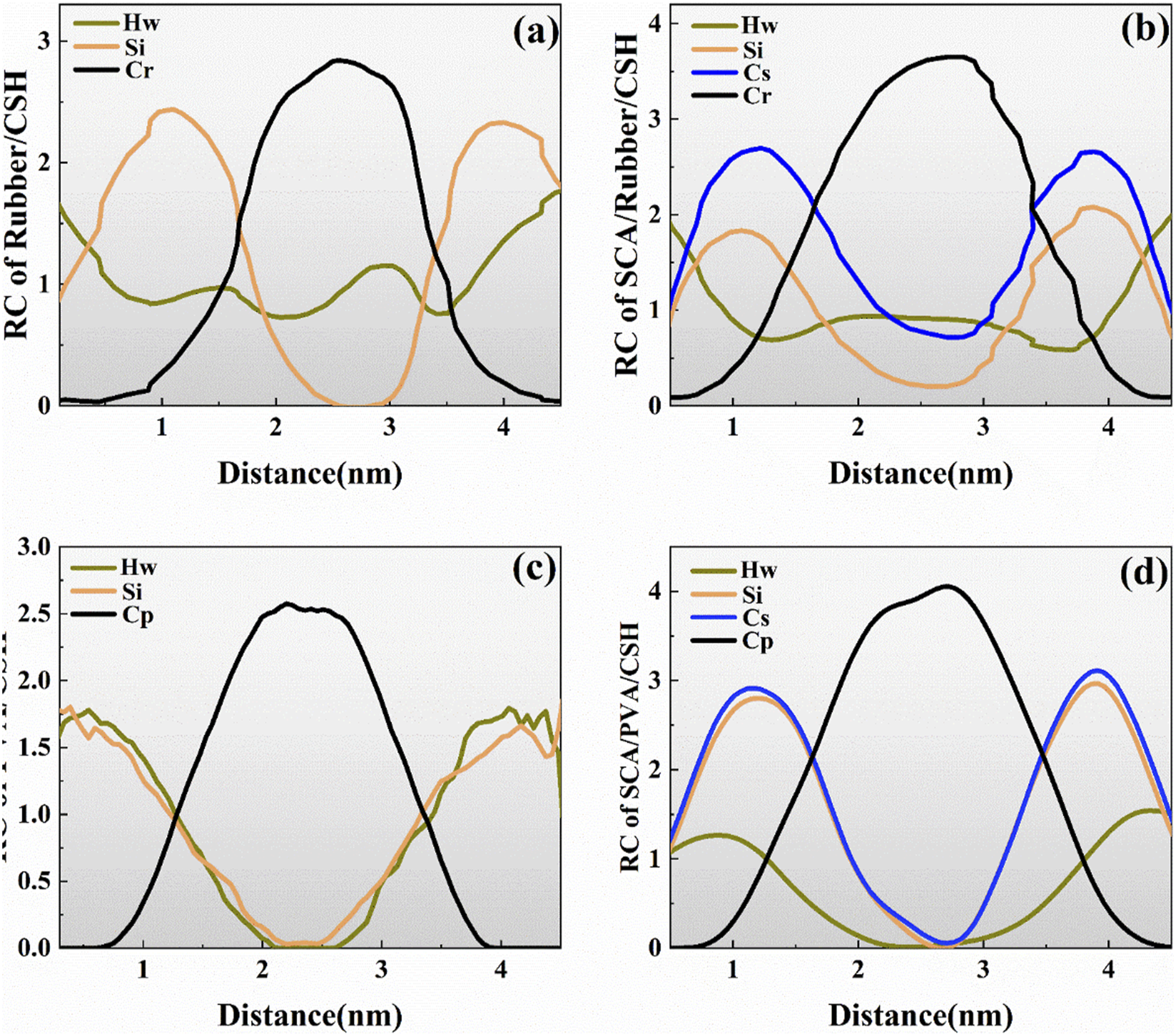
Application of frame structure
Door structure test
To validate the practical application of silane coupling agent-modified PVA fiber-rubberized concrete in engineering, this study plans to conduct experiments on plain concrete, rubberized concrete, PVA fiber-rubberized concrete, and modified PVA fiber-rubberized concrete using a simple portal frame structure. The structure will be configured with HRB300 main reinforcement with a double row of 12 mm diameter and HRB300 stirrups of 8 mm diameter spaced at 150 mm intervals. The overall structure dimensions are 1000 mm in length and width, with beam and column cross-sectional dimensions of 150 mm * 150 mm, and a concrete cover thickness of 25 mm. The concrete mix proportions will be determined according to the JGJ55-2011 “Code for Design of Concrete Mix Proportions,” with the PVA content as the main research parameter.
Modified PVA fiber rubber concrete mix ratio.
Notes: PC—Plain concrete; RC—Rubber particles; PVA—PVA fiber; RC20—Rubber volume substitution ratios of 20%; PVA1.0%—PVA fiber volume fractions of 1.0vol%, respectively; KH560—KH560 modifier volume fractions of 1.5vol%.
Experiment method
After casting, the specimens were demolded within 24 h and cured for 28 days under standard conditions (20 ± 2°C, humidity ≥95%). Loading was conducted using a reaction frame, with the frame beam positioned directly beneath the reaction frame. Due to limitations in the descent height of the compression machine, a 20 mm thick steel plate was placed on the ground, and two feet were placed flat on the steel plate. Simultaneously, a steel crossbeam was placed at mid-span to increase the test height. The load was applied to the mid-span upper surface through the compression machine, controlled entirely by the computer at the experimental platform. Strain gauges were affixed beneath the mid-span center of the crossbeam to measure mid-span strain, and displacement gauges were arranged at mid-span to measure mid-span displacement. The loading procedure and sensor placement on-site are illustrated in Figure 19(a). Gradual loading was applied using the compression machine until the frame beam failed, as depicted in Figure 19(b), with each load increment ranging from 2 to 6 kN. Strain and displacement at mid-span were recorded at each load level, and the appearance of cracks was observed and documented. Instrument placement and loading.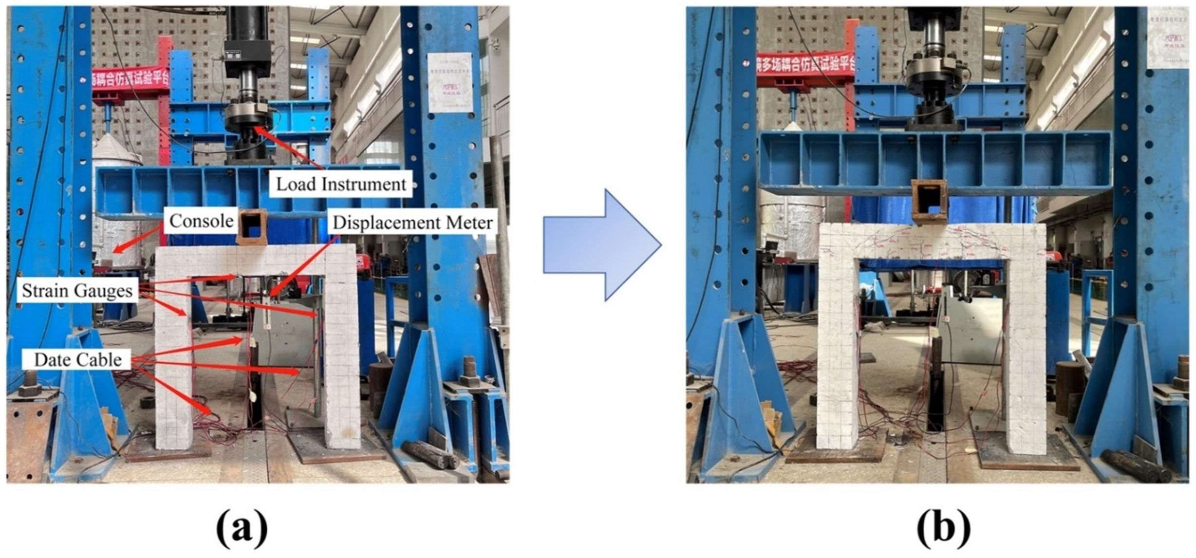
Bearing capacity analysis
Based on experimental observations, cracks in all four frame structures initially appeared at the mid-span or near the mid-span of the beams, indicating that the load-carrying capacity of the frame structures is primarily determined by the beams. For reinforced concrete frame structures, if the initiation of concrete cracks is used to determine their load-bearing capacity, the test data reveals load-bearing capacities of 27, 24.5, 30.4, and 32 kN for the four frame structures, respectively. Compared to the load-bearing capacity of the plain concrete frame structure, the load-bearing capacity of the rubberized concrete frame structure decreased slightly, with a reduction of 9.25%. This reduction can be attributed to the lower strength of rubber particles compared to other aggregates in concrete, leading to localized weak areas in the material. Additionally, rubber particles, being hydrophobic, can trap air on their surfaces, and since cement is hydrophilic, weak bonding interfaces are formed, increasing the porosity of the concrete specimens.
The rubberized concrete frame structures with added PVA fibers exhibited significantly higher load-bearing capacities than the plain concrete frame structure. This improvement can be attributed to the effective prevention of microcrack initiation and propagation by PVA fibers in concrete, greatly enhancing the ductility and toughness of rubberized concrete. The use of modifiers can alter the surface characteristics of fibers or increase the bonding quality between fibers and cementitious materials. The results with KH560 modifier suggest that judicious use of modifiers can either maintain or slightly increase the load-bearing capacity of frame structures.
Charting the displacement/strain relationships against loads for the four structural configurations, as depicted in Figure 20. Figure 20(a) reveals that the displacement-load correlation for each framework structure is predominantly linear, with comparable slopes. Notably, the plain concrete frame exhibits consistently larger mid-span displacements, accompanied by the emergence of longitudinal through cracks parallel to the loading direction as the load intensifies. In contrast, the rubberized concrete frame, with only rubber admixture, presents a singular diagonal crack and a few micro-cracks parallel to the loading direction. This is attributed to the rubber aggregates’ capacity to endure substantial tensile deformation, redirecting crack propagation around rubber particles, thereby retarding crack expansion and ameliorating the overall disintegration of the concrete framework. Relationship curve between trans-mid displacement/strain and load across four frame structures.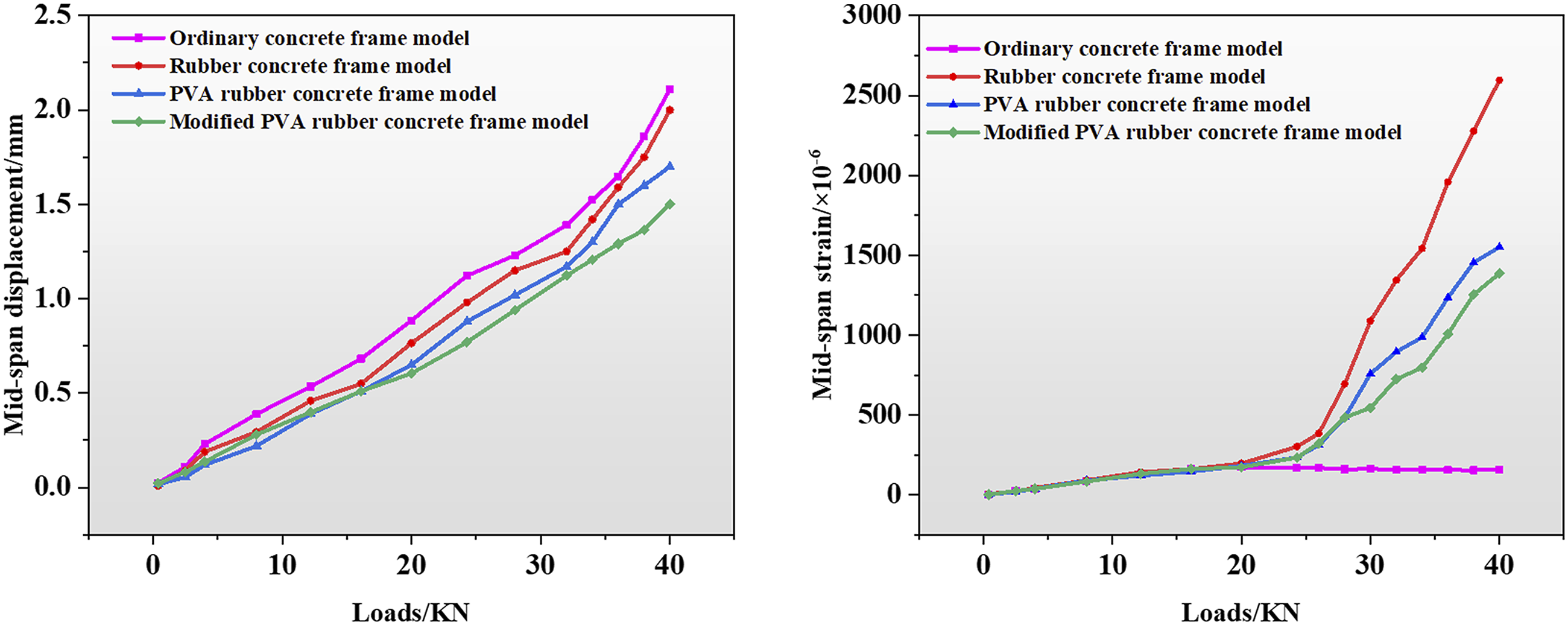
With the incorporation of PVA fiber materials, the width of through cracks diminishes, while the quantity of surface microcracks increases. This signifies that fiber inclusion has the potential to impede crack propagation and enhance the concrete’s resistance to brittle failure. Moreover, specimens containing both fibers and rubber exhibit superior improvements in deformation performance compared to those with singular rubber or fiber additions, showcasing enhanced specimen integrity and preventing cementitious slurry detachment along specimen edges.
Examining Figure 20(b), it becomes evident that the late-stage strain increase on all four curves is rapid and sustained. This phenomenon arises as the strain gauges on the framework models precisely span the emerging cracks, leading to an infinite strain increase until the strain gauges rupture. In comparison to the plain concrete frame, the rubberized concrete frame, due to the incorporation of rubber particles, forms a blunted region at the tip of concrete cracks, reducing the stress intensity factor, retarding crack extension, and thereby improving concrete ductility. The strain-load relationship curve for the PVA fiber-rubberized concrete framework exhibits a slowed late-stage growth trend. This can be attributed to the chaotic distribution of PVA fibers in the rubberized concrete after mixing. As the concrete undergoes compression, the fibers act as bridges, transmitting stress to the cement matrix on either side of the cracks, redistributing concentrated stress within the concrete, impeding microcrack expansion, and fully leveraging the concrete’s load-bearing capacity, thus enhancing the rubberized concrete’s ductility.
Conclusions
This study employs a multiscale analytical approach to investigate the synergistic reinforcement effects of silane coupling agent (SCA) and PVA fiber materials on rubberized concrete. SCA has been proven to effectively enhance the bond performance between PVA fibers, rubber, and the cement matrix, thereby elevating the mechanical properties of the concrete material. Framework experiments further validate the outstanding mechanical and bond performance of PVA fiber-rubberized concrete in concrete frame structures. The key conclusions are outlined as follows: (1) Macroscopic mechanical testing results indicate that the synergistic action of PVA fibers and SCA enhances the mechanical properties of rubberized concrete, resulting in a 1.25-fold increase in compressive strength and a 1.81-fold increase in flexural strength at 28 days. (2) SEM observations reveal a tighter interface binding between SCA-treated rubber particles/cement and PVA fibers/cement, thereby improving the mechanical performance of the concrete. (3) XRD and FTIR analyses demonstrate that the addition of SCA delays the hydration of cement, increases the quantity of hydrated calcium silicate gel, and optimizes the composition of cement hydration products at the interface. (4) Molecular dynamics simulations indicate that SCA forms Si-O-Si chemical bonds with non-bridging oxygen atoms in the C-S-H matrix. Numerous hydrogen bond interactions occur between rubber/PVA. The introduction of SCA stabilizes the hydrogen bonds and coordination of Ca-H, forming a stable PVA/C-S-H and Rubber/C-S-H interface system, thereby enhancing the interface bonding strength. (5) Portal frame structure tests illustrate a significant improvement in material strength and stiffness due to the synergistic effect of PVA fibers and SCA. This enhancement can further ameliorate structural strength, deformation behavior, and load-bearing capacity. The judicious use of this material can reduce costs while ensuring structural strength.
Footnotes
Declaration of conflicting interests
The author(s) declared no potential conflicts of interest with respect to the research, authorship, and/or publication of this article.
Funding
The author(s) disclosed receipt of the following financial support for the research, authorship, and/or publication of this article: This work was supported by the Henan Province Science and Technology Research Project (232102320173), Funds Plan of Henan University of Technology (2020ZKCJ21), Zhengzhou Collaborative Innovation Project (21ZZXTCX09) and the Young Backbone Teacher Project of Henan University of Technology (2019).