
Abstract
Ultraviolet (UV) radiation has a detrimental effect on the outdoor lifetime of PVC film materials. TiO2 nanoparticles, as commonly used UV absorbers, still suffer from poor transparency, high photocatalytic effect, and poor dispersion in PVC matrix. To mitigate these effects effectively, titanium dioxide nanorod @ silicon dioxide (TNr@SiO2) was synthesized and used as an anti-UV aging agent for polyvinyl chloride (PVC). The agglomeration effects of TiO2 nanoparticles in PVC films were solved by synthesizing TNr, and the catalytic effects of TiO2 was reduced by growing SiO2 on the TNr surface. Scanning electron microscopy, Fourier transform infrared spectroscopy, X-ray diffraction, X-ray photoelectron spectroscopy, and UV-visible spectroscopy were utilized to demonstrate the excellent dispersion and low photocatalytic effects of the synthesized TNr@SiO2. Compared with pure PVC film, the color change of TNr@SiO2/PVC composite film is not evident after 800h of UV aging, and the retention of mechanical properties were 93.94%. Compared with TiO2/PVC, TNr@SiO2/PVC composite film has better transparency. Results show that TNr@SiO2 can maintain the properties of PVC better because the electrons of TNr@SiO2 are excited to form a positively charged hole after the absorption of UV light, and then the hole electron pairs are recombined and converted into thermal energy, which improves the durability of PVC. Therefore, this highly transparent TNr@SiO2/PVC composite film with low photocatalytic activity and high UV resistance will soon be applied in large-scale industrial production.
Keywords
Introduction
Polyvinyl chloride (PVC) is one of the world’s top five general-purpose plastics that extensively applies to industry, agriculture, construction, household goods, and medicine, because of its outstanding internal properties, such as wear resistance, electrical insulation, and well-established production processes.1–4 In 2022, PVC global production volume reached more than 46 million tons, and the global PVC industry output is expected to show an upward trend. However, the chlorine atoms in the PVC molecule are particularly sensitive to ultraviolet light, especially in the UV-B and UV-C regions; the chlorine atoms in PVC absorb the energy of the ultraviolet light, which leads to the dissociation of the chlorine atoms and the production of chlorine free radicals (Cl−).These free radicals initiate chain reactions in the PVC structure, leading to cleavage of the molecular chain and structural changes; subsequently, the presence of chlorine free radicals prompts the cleavage of the PVC molecular chain, leading to chain breakage and molecular structure instability.5–7 Under the action of oxygen, the polyolefin structure on the PVC molecular chain will undergo two competitive reactions, namely oxidative crosslinking and oxidative degradation, which will deteriorate the mechanical properties of the PVC and shorten the service life.8–10 Therefore, the addition of UV absorber is essential improving the stability of PVC.
Nano inorganic materials are stable in nature and have strong absorption and shielding effects on UV rays.11,12 Among these nano inorganic materials, TiO2 nanoparticles can reflect UV light in UVA and absorb UV light in UVB.13–17 Thus, it can be used as an effective UV absorber. Sokhandani P 18 prepared polyvinyl chloride (PVC) nanocomposites by blending synthetic titanium dioxide nanorod with commercial titanium dioxide nano powders (Degussa P25), and improved the mechanical properties of PVC nanocomposites after aging. Unfortunately, due to the small particle size, high specific surface area and easy agglomeration, TiO2 nanoparticles used as UV absorbers have adverse effects.19–21 The dispersibility problem of of TiO2 nanoparticles in PVC matrix can be solved by changing the morphology of TiO2 nanorod (TNr). 22
Moreover, TiO2 nanoparticles absorb UV rays and stimulate the production of superoxide and hydroxyl free radicals on their surface, which causes PVC to degrade.23–25 Therefore, the photocatalytic activity of TiO2 nanoparticles must be reduced. To reduce the photocatalytic activity, many reports on the modification of TiO2 with inert materials such as SiO2 and Al2O3, have been published.26–31 Furusawa T et al. 32 discovered that the photocatalytic effect was inhibited by coating rutile TiO2 with SiO2. Similarly, Stathatos E et al. 33 prepared organic/inorganic nanocomposite 34 films by sol-gel method to obtain efficient TiO2 nanoparticles.
In this work, titanium dioxide nanorod @ silicon dioxide (TNr@SiO2) was prepared by hydrothermal synthesis reaction and sol-gel method, which solved the dispersity problem of nano TiO2 filler and inhibited the high photocatalytic effect of nano TiO2 filler. The morphology, phase and composition were analyzed by electron microscopy, infrared, X-ray diffraction (XRD), X-ray photoelectron spectroscopy (XPS), and thermogravimetric methods. PVC composites with different additive amounts of TNr@SiO2 were prepared. The UV resistance of TiO2/PVC, and TNr@SiO2/PVC composite films were studied by using UV aging test chamber.
Materials and methods
Materials
The TiO2 for the synthesis of TNr, Methylene blue (MB) and ammonia liquor were purchased from Shanghai Macklin Biochemical Co., Ltd. Sodium hydroxide (NaOH), Tetraethyl orthosilicate (TEOS) were purchased in Shanghai Aladdin Bio-Chem Technology Co., Ltd. Polyvinyl chloride (PVC) resin powder were provided by Zhongyanjilantai polymer Materials Co., LTD.Barium zinc stabilizer and plasticiser is supplied by Zhejiang Jinda New Materials Co., Ltd.All chemicals were analytical reagent. The experiment also made use of 99% anhydrous ethanol and deionized water.
Synthesis of TNr@SiO2
The one-step hydrothermal method was used to make TNr. First, 0.5 g TiO2 nanoparticles were dispersed into 50 mL 10 mol/L NaOH aqueous solution under ultrasonic conditions. Then, the solution was put into a hydrothermal reactor lined with polytetrafluoroethylene and heated to 180°C and reacted 24 h. Subsequently, the reaction products were removed and centrifuged successively. Until the pH of the rinse solution reached 7.0 using 0.1 mol/L HCl and deionized water. Finally, the deposit was freeze-dried for 24 h.
The TNr@SiO2 was synthesized by Sol-gel method. First, TNr was dissolved in a solution of 150 mL of C2H5OH and 50 mL of deionized water, sonicated, and 1 mL of TEOS was dropped into a three-necked flask through a rubber-tipped buret, 15 mL of ammonia was slowly added dropwise through a burette, and the mixture was stirred vigorously for 24 h at room temperature. Subsequently, the prepared suspension was washed with C2H5OH to a Ph of 7, centrifuged, and finally the samples were freeze-dried for 48 h. The resulting product was named TNr@SiO2. The steps of synthesis of TNr@SiO2 were demonstrated in Figure 1. Flow chart of TNr@SiO2 preparation.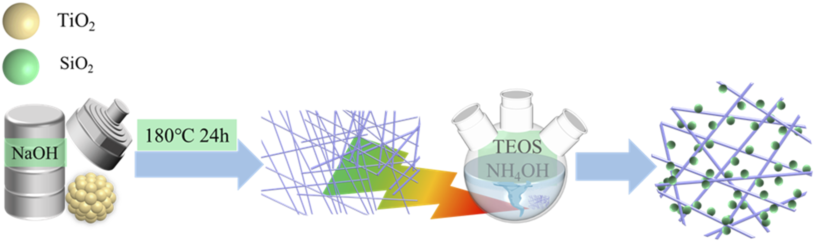
Preparation of UV resistant PVC film
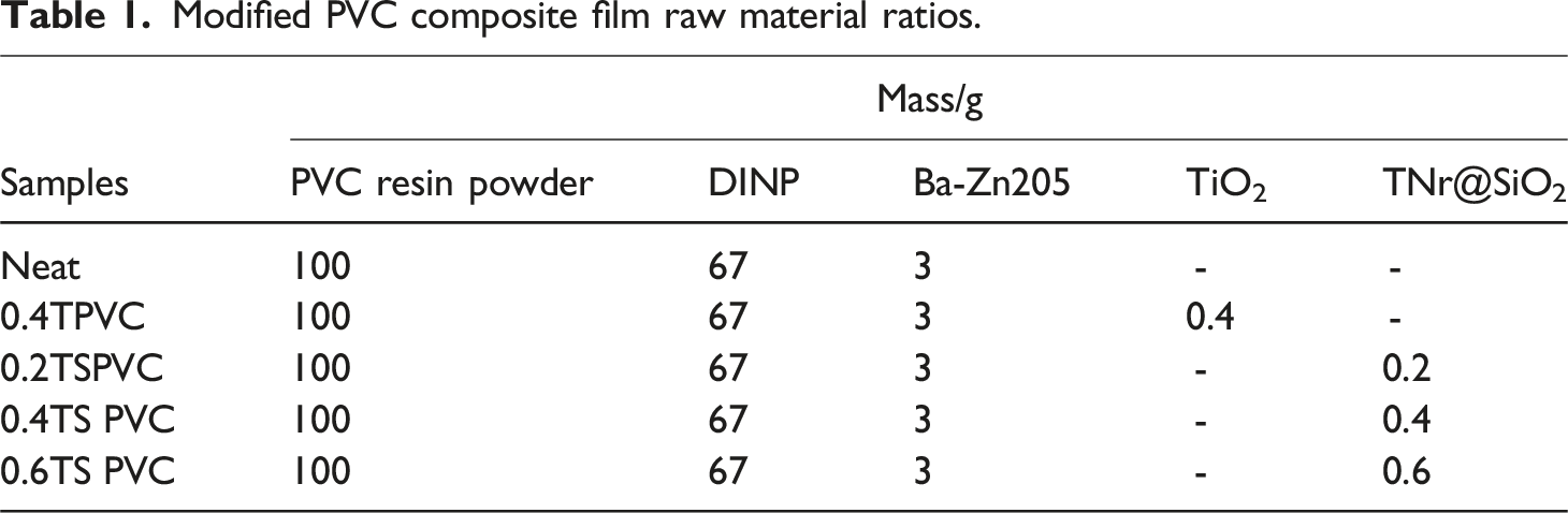
Modified PVC composite film raw material ratios.
Characterization of Materials
The microstructure of the samples was observed by scanning electron microscopy (SEM, ULTRA 55). Fourier transform infrared spectroscopy was obtained using the Nicolet IS50 FTIR spectrometer. The crystal phase composition of the sample was determined in scanning range of 10–80° by X-ray diffraction analysis (XRD, A8 Advance) at a speed of 5°/min. Scanning electron microscopy (SEM, Ultra55) was used to examine the microstructure of the samples. The Nicolet IS50 FTIR spectrometer was used to obtain Fourier transform infrared spectroscopy. X-ray diffraction analysis (XRD, A8 Advance) was used to analyze the sample’s crystal phase composition in the scanning range of 10–80 at a speed of 5°/min. The samples’ porosity developed was observed by adsorption isotherms (N2 at 77 K and CO2 at 273 K were conducted at ambient pressure of 760 mmHg). Utilizing a Quantachrome Instruments Autosorb-6 piece of equipment, all characterizations were completed. The apparent surface area was calculated using the BET method with P/Po values ranging from 0.0001 to 0.01. With the use of an X-ray photoelectron spectrometer (XPS, ESCALAB Xi +), the chemical bonding state was determined. STA409 PC thermogravimetry (TG, NETZSCH, Germany) was used to measure the thermal behavior of the nanoparticles from room temperature to 600°C with a heating rate of 10°C min-1. The UV-Vis spectra in the 200–500 nm wavelength range were measured using a UV-Vis spectrophotometer (UV2600, Shimadzu).
Photocatalytic performance test
The experiment of organic degradation testing using a 20.0 mg/L MB solution was done to confirm the low photocatalytic effect of TNr@SiO2. A 300 W xenon lamp with an optical power density of 45 mW/cm2 was used as the light source (Beijing Aolite Technology Co., Ltd). Following a 60-min magnetic stir, the absorbance of the MB solution was assessed. To be more precise, 50 mL of the MB solution each received 0.1 g of the powders TNr@SiO2 and TiO2. The combination was exposed for 0 h, 1 h, 2 h, and 4 h after reacting for 30 min in the dark [31,32]. After that, the reaction solution was taken out and centrifuged to conduct a UV-Vis test. Efficiency of deterioration is determined by the equation (1)
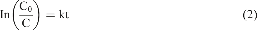
We adopted the Langmuir-Hinshelwood pseudo-first-order kinetic model with a k value of equation (2) to clearly distinguish the activity of TNr@SiO2.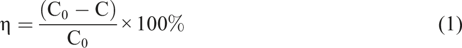
Polyvinyl chloride Composite Film UV Resistance Test
The accelerated weathering test of PVC composite film was carried out in a QUV aging experiment box under conditions of continuous light cycle, 60°C and irradiation of 0.89 W/m2 at 310 nm.
Color difference (ΔE) and ΔLab of PVC composite film were measured by the KONICA MINOLTA CM-700d spectrophotometer (Japan). The color change of the PVC composite film was measured by Canon EOS 90D (Japan).
Mechanical stretch test was measured by Instron3400 universal testing machine (America).
Results and discussion
Characterization of TNr@SiO2
Scanning electron microscopy (SEM) was used to examine the morphology of TiO2 and TNr@SiO2 nanoparticles. As shown in Figure 2(a), TNr exhibits a typical cylindrical rod-like nanostructure with a relatively smooth surface. The length and diameter of a single rod was approximately 2–10 µm and 200 nm, respectively. Surprisingly, compared with pristine TiO2, TNr hardly had any agglomeration, because the morphology and size of titanium dioxide were changed by hydrothermal synthesis. The specific surface area and surface energy of titanium dioxide decreased, leaving it in a thermodynamically stable system. As shown in Figure 2(b), the TNr@SiO2 surface is slightly rougher than that of TNr due to the uniform growth of SiO2 on the surface of TNr. According to the element scanning image (Figure 2(c)), Si elements could be observed in the outer layer of TNr, thereby further confirming that the surface of TNr successfully grew SiO2 nanoparticles. SEM images (a, b) of TNr, TNr@SiO2 and elemental mapping (c) of the elements C, O, Si and Ti of TNr@SiO2.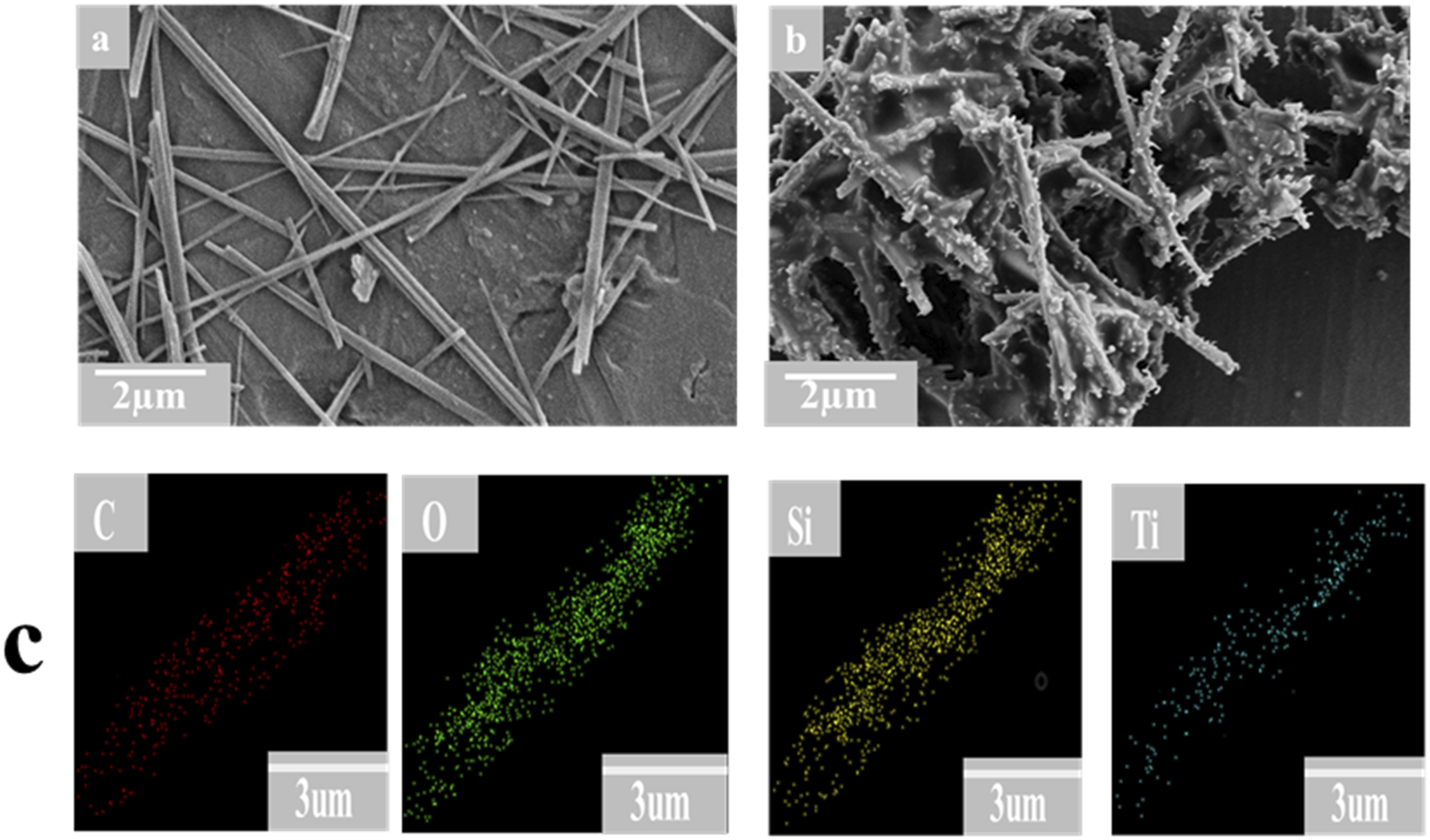
The FT-IR,XRD, and BET resluts of TNr@SiO2 nanoparticles were shown in Figure 3. As shown in Figure 3(a), the stretching and bending vibrations of O-H absorbing water led to the peaks at 3428 cm−1 and 1638 cm−1, respectively. Si-O-Si asymmetric stretching vibrations were responsible for the peaks at 1233 cm−1 and 1069 cm−1, which showed that SiO2 had formed on TNr. The faint peak at 963 cm−1 was brought on by the Ti-O-Si bond’s characteristic stretching vibration, confirming that TNr was joined to SiO2 by a chemical connection created by the replacement of Ti with Si. Additionally, the Ti-O-Ti stretching was responsible for the peak at 556 cm−1. FTIR Spectra, (a) XRD Spectra, (b) Thermogravimetric graphs (c) and UV absorption Spectroscopy (d) of TiO2, TNr@SiO2.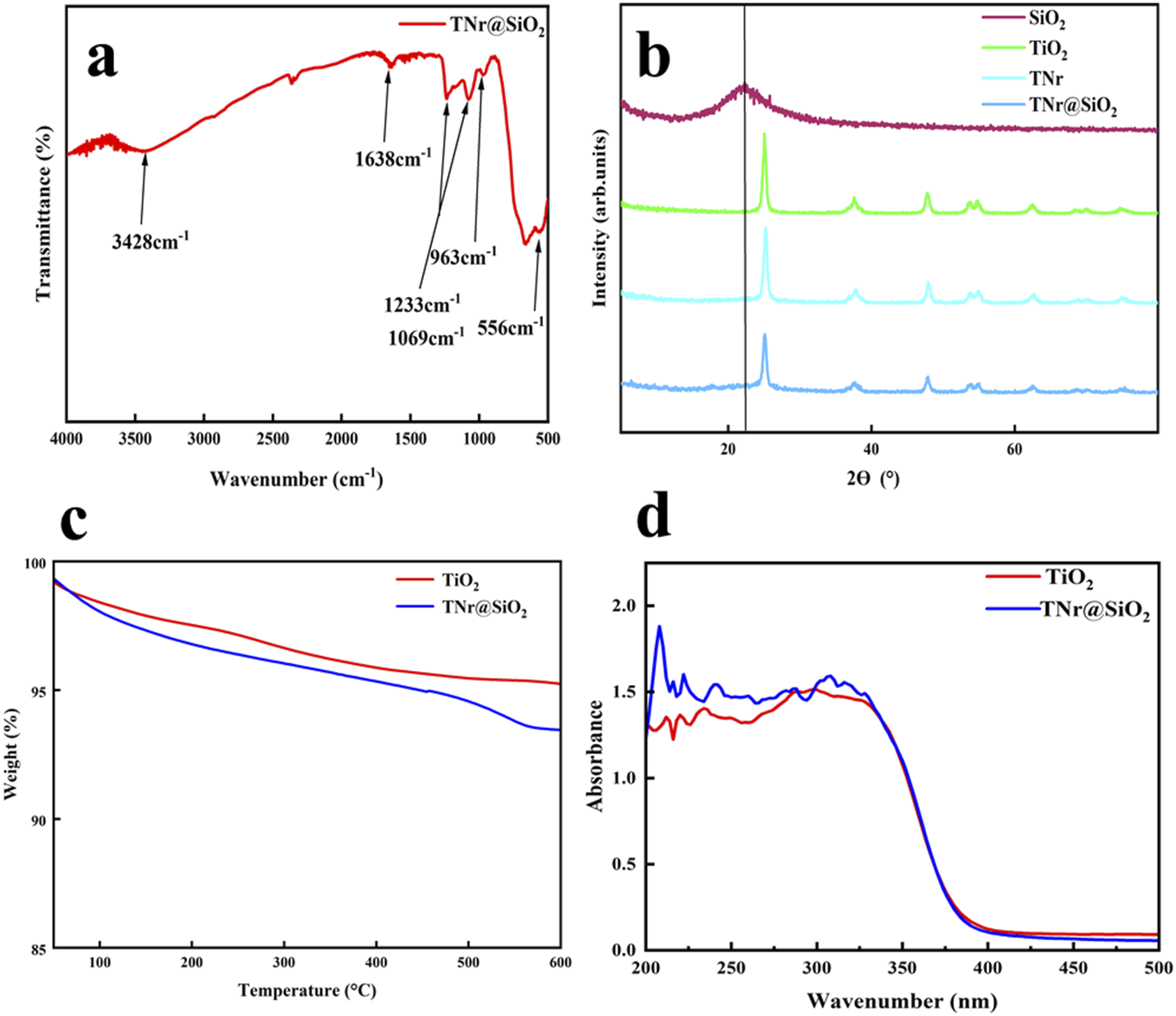
The TNr@SiO2 structure was further confirmed by XRD. Figure 3(b) shows the XRD of SiO2, TiO2, TNr and TNr@SiO2 nanoparticles. 2θ diffraction peaks are shown at 25.37°, 37.03°, 24.12°, 53.97°, 55.0°, and 62.74°. The indices of these diffraction peaks were assigned to (101), (103), (200), (105), (211), and (204) anatase phases, which are successfully in a good agreement with JCPDS 00-021-127. Also, due to the amorphous state of SiO2, detecting the characteristic peak of SiO2 on TNr@SiO2 was difficult, but a curve bump could be observed in the diffraction background of 2θ = 22.3°. The intensity of TNr@SiO2 diffraction peaks was likewise smaller than that of TNr and TiO2 due to the decreased crystallinity of TNr@SiO2.
The interfacial interaction between TNr and SiO2 was obtained by XPS. High-resolution XPS for C1s, O1s, Ti 2p and Si 2p and the full spectrum are shown in Figure 4. XPS spectra of TNr@SiO2 and TiO2 (a) and high resolution XPS spectra of C1s (b), O1s (c), Ti 2p (d) and Si 2p (e).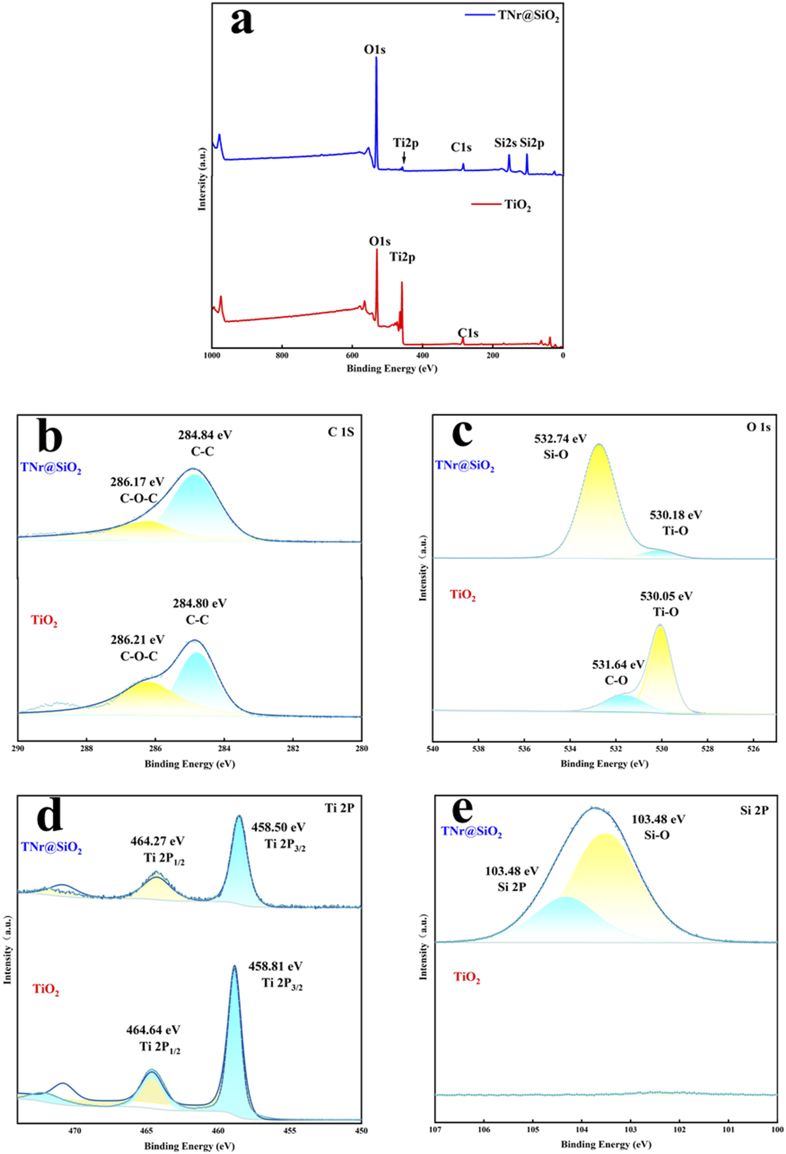
As shown in Figure 4(a), TNr@SiO2 was composed of C, Si, Ti and O elements. The high-resolution C1s spectra of TNr@SiO2 shown in Figure 4(b) clarified that the compound contains two C1s peaks. The C-C bond-driven peak at 284.84 eV was remarkably stronger than the C-O-C-driven peak at 286.21 eV. As shown in Figure 4(c), the O1s peak bonding energy of TiO2 nanoparticles was 530.05 eV. Compared with TiO2 nanoparticles, two different O1s peaks of TNr@SiO2 were observed at 532.74 eV and 530.18 eV. The lower binding energy is associated with Ti, TNr@SiO2 for Ti-O bonds, whereas the other is associated with Si for Si-O bonds. The peak intensity of Si-O bonds is remarkably stronger than the peak intensity of Ti-O bonds, indicating that SiO2 was successfully loaded on the TNr surface. 35 In addition, the O1s peak of TNr@SiO2 had a chemical shift of +0.13 eV with respect to the Ti-O bond of TiO2, due to the greater electronegativity of Si than Ti. Meanwhile, as shown in Figure 4(d), the binding energy of Ti2p 3/2 peaks was 458.81 eV, whereas that of TNr@SiO2 was reduced to 458.50 eV. The binding energy of Ti2p 1/2 peaks was 464.64 eV, whereas that of TNr@SiO2 is reduced to 464.27 eV. Finally, as shown in Figure 4(e), the characteristic peak of Si2p appeared on TNr@SiO2, and the bonding energy of Si-O was 103.800 eV, while TiO2 exhibited a stable curve without any peak, indicating that SiO2 was successfully loaded on TNr. The binding energy of the characteristic peak of Ti2p was shifted (from 458.81 eV to 458.50 eV) after the loading of SiO2, indicating the influence of Si element on the binding energy of Ti element.
The thermogravimetric (TG) curves of TiO2 and TNr@SiO2 are shown in Figure 3(c). TiO2 was comparatively stable and slightly broken down. Between 400°C and 600°C, the weight of TNr@SiO2 decreased by 1.515%, which was attributable to the reduction of -OH on TiO2 surface and the breakdown of the remaining organic groups of TEOS. The surface of TNr was successfully coated with SiO2 according to the TG results.
To study the UV absorption of TiO2 and TNr@SiO2, UV absorbance test was conducted. As shown in Figure 3(d), compared with TiO2, TNr@SiO2 absorbed light in the UVA and UVB ranges better and exhibits λ max at 290–320 nm. The band gap also increased after SiO2 doping and the absorption peak moved in the long wave direction.
Photocatalysis performance of TNr@SiO2
By eliminating the MB solution, a photocatalytic degradation study was performed to gauge the photocatalytic performance of TNr@SiO2. Figure 5(a) and (b) show the UV-Vis absorption spectra of MB degradation by TiO2 and TNr@SiO2. Figure 5(a) and (b) are photocatalytic degradation diagrams based on absorbance values at a wavelength value of 664 nm. As shown in Figure 5(a), with the increase in reaction time, TiO2 has a greater catalytic degradation rate. SiO2 has a low ability to absorb photons. After loading on the surface of TNr, the photocatalytic activity was inhibited, and Figure 5(b) shows that TNr@SiO2 has a smaller catalytic degradation rate for MB. The UV-Vis absorption spectra of TiO2 (a) and TNr (b). The photocatalytic degradation performance diagram (c) and the firstorder kinetic curve diagram (d).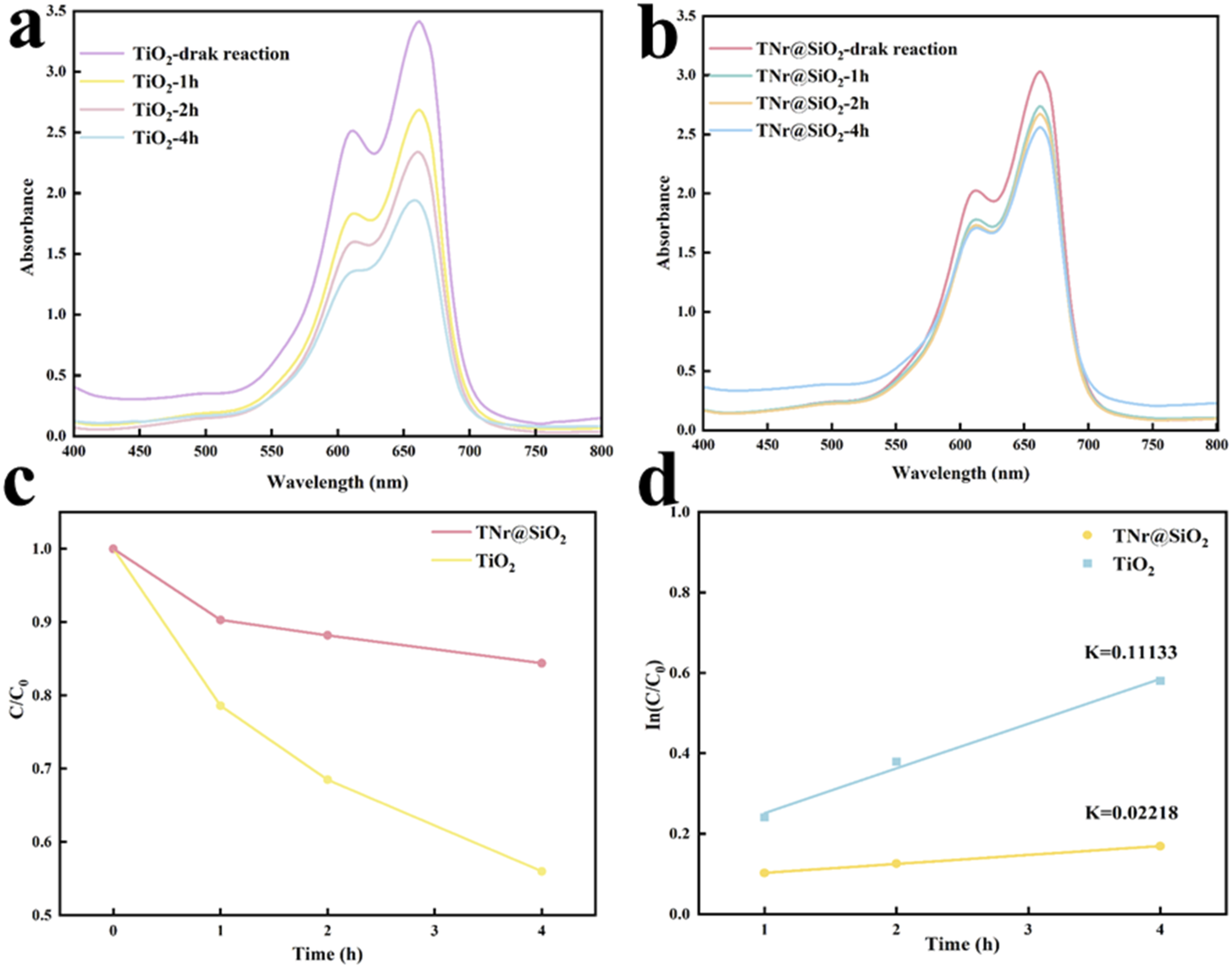
3.2-(1) and (2) formulas are used to compute the MB degradation rate, and kinetic fitting is used to further examine the degradation rate. In Figures 5(c) and (d), the calculated results show that the reaction rate constant K of TiO2 and TNr@SiO2 is 0.11133 and 0.02218, respectively. Surprisingly, the reaction rate constant of TNr@SiO2 is 0.2 times that of TNr@SiO2. Therefore, UV-resistant PVC films were prepared by using TNr@SiO2, which can inhibit the photocatalytic degradation effect, as UV absorber.
Polyvinyl chloride composite film anti-UV performance analysis
Morphology analysis of PVC composite film
Figure 6 displays the SEM images of the PVC composite film prior to and following 800h of UV aging. From Figure 6(a) and (b), the surface of the PVC film was relatively smooth before UV aging. After 800h of UV irradiation, the PVC film surface appeared obvious fracture mouth, and the surface became rough, due to that the polyolefin that formed an excited singlet state after absorbing photons in the PVC film. The excited singlet state could be deactivated by irradiation and non-irradiation. The excitation energy can also migrate or be transferred from one polyene to another and then break at the most unstable bond (e.g, allyl chloride). From Figure 6(c) and (d), the surface of 0.4TPVC composite film before aging was rougher than all other samples. The surface energy of TiO2 nanoparticles is very large, which was in a thermodynamically unstable state. They made the particles stick together and agglomerate, resulting in poor dispersion in the matrix. After 800h of UV irradiation, no cracks and fracture openings were observed on the surface of 0.4TSPVC composite film, that is, only some tiny micropores appeared, and the retention of film surface morphology was high. Because TiO2, as a UV absorber, could absorb UV light, thus making the PVC film UV resistant. From Figure 6(e)–(j), different contents of TNr@SiO2 were added with PVC films. All samples had relatively smooth surfaces before UV aging. The results indicated that TNr@SiO2 had lower surface energy and was more compatible with the substrate. The modified TiO2 could solve the agglomeration problem of TiO2 nanoparticles by decreasing the high surface energy. After 800 h of UV irradiation, the extent of holes and fractures on the surface of PVC composite film decreased with the increase in TNr@SiO2 addition. As shown in Figure 6(f), 0.2TSPVC composite film showed fine cracks and holes after 800 h of UV irradiation. This phenomenon may be due to the low addition of TNr@SiO2, resulting in PVC composite film with poor UV resistance. 0.4TSPVC composite film did not show any pores after 800 h of UV irradiation, and some fine incompletely fractured fissures could be observed (Figure 6(h)). The results indicated that the encapsulation of an appropriate amount of SiO2 could not affect the UV resistance of TNr. From Figure 6(j), 0.6TSPVC composite film still had smooth surface after 800 h of UV irradiation, and only a small crack appeared. SEM of the PVC samples under different UV irradiation times.
In summary, when the added amount of TNr@SiO2 reaches 0.4%, the PVC composite film exhibited a more excellent anti-UV effect.
Color change test of PVC composite film
Undoubtedly, PVC composite films absorb and degrade UV light, thereby producing colored groups, which result in the yellowing of PVC composite film. Figure 7 illustrates the digital photographs of PVC composite film prior to and following 800 h of UV aging. After 800h of aging, the pure PVC film experienced a remarkable color change, that is from transparent and colorless to yellowish brown. The rapid yellowing phenomenon indicated that the UV resistance of the pure PVC film was poor. The transparency of PVC film was remarkable reduced after the addition of TiO2, which was caused by the high opacity of TiO2. The color change in 0.4TPVC composite film was not evident before and after aging, which indicated that TiO2 itself had excellent anti-UV performance. After adding TNr@SiO2, the color of the PVC composite film was transparent almost as much as that of pure film, and the color changes are not obvious before and after aging. This finding indicated that TNr@SiO2 maintained the excellent anti-UV performance of the original TiO2. The degree of color change in 0.4TSPVC composite film was significantly reduced after 800 h of aging. Digital photos of the PVC samples under different UV irradiation times.
To study the colorimetric changes in PVC films better, △Lab. and △E values were measured before and after aging. From Figure 8(a)–(d), the chromaticity index △a, △b and the total color difference △E of the 0.4TPVC composite film were greater than those of the pure film during the whole UV aging process, due to the high reflectivity of TiO2, leading to the decrease of the transparency of the film. △Lab (a, b, c) and △E (d) values aging 800 h’s UV accelerated weathering test and change ratio of △Lab and △E (e and f).
However, the rate of change of chromaticity index and color difference △E after UV aging were smaller than that of pure film (Figure 8(e)–(f)). The ∆E change rate of 0.4TPVC composite film after aging is 195.52%, whereas the pure PVC film after aging is 222.92%; compared with the latter, the △E change rate of 0.4TPVC composite film decreased by 26.5%. The ∆a change rate of 0.4TPVC composite film after aging is 152.30%, whereas the pure PVC film after aging is 416.91%; compared with the later, the △a change rate of 0.4TPVC composite film decreased by 255.51%. The ∆b change rate of 0.4TPVC composite film after aging is 219.21%, whereas the pure PVC film after aging is 32.51%; compared with the later, the △E change rate of 0.4TPVC composite film decreased by 102.40%. TiO2 had excellent anti-UV effect, but the transparency is poor.
Compared with 0.4TPVC composite film, the values of △L, △a, △b, △E and the rate of change after aging of TSPVC composite film were lower than those of TPVC composite film. Meanwhile, with the increase in TNr@SiO2 addition, the rate of change of chromaticity index and the rate of change of chromaticity gradually decreased. 0.2, 0.4 and 0.6 additions of TNr@SiO2 film before and after aging had △E change rate of 195.56%, 185.85%, and 195.44%, respectively, whereas the PVC film was 222.92%, which was remarkably lower than the pure PVC film.
Mechanical property of PVC composite film
Aging phenomena such as discoloration, chalking, and cracking occur after UV irradiation of PVC composite films, which leads to the formation of reactive chemical bonds, in the main chain of PVC. These reactive chemical bonds break after further oxidation or UV irradiation, leading to polymer chain breakage, which results in the deterioration of the mechanical properties of PVC composite films.
36
As shown in Figure 9, the breaking strength of pure PVC composite film was reduced from 16.08 MPa to 10.86 MPa, and the retention rate of mechanical properties was only 67.55%.The breaking strength of 0.4TPVC film was reduced from 15.64 MPa to 13.26 MPa, and the retention rate of mechanical properties was 84.75%, which was obviously better than that of pure PVC film. This is due to the excellent absorption and reflection properties of TiO2 on UV rays. Compared with 0.4TPVC composite film, with the increase of TNr@SiO2 addition, the fracture strength of TSPVC composite films gradually increased, and the breaking strength decreased insignificantly before and after aging, and the retention rate of mechanical properties was 81.94%, 93.94% and 97.84%, respectively, which indicated that the appropriate SiO2 loading would not affect the UV absorption performance of TNr, and ensured the excellent mechanical properties of PVC composite film. Breaking strength of PVC samples under different UV irradiation times.
Influence of UV Irradiation on the chain structure of PVC composite film
In order to further investigate the effect of UV irradiation on the molecular chain structure of PVC composite films and to reveal its UV-resistant mechanism, the FTIR spectra of PVC composite films under different UV irradiation times were tested. From Figure 10(a), it can be seen that the stretching vibration absorption peak of carbonyl group (at 1723 cm−1) exists in the PVC composite film before UV aging, which is caused by the carbonyl group contained in the plasticizer DINP. After 800h of aging, the carbonyl group of unmodified PVC composite film showed a significant increase in the carbonyl group expansion and vibration absorption peaks, which indicated that the unmodified PVC composite film formed carbonyl group after dehydrochlorination of PVC by UV irradiation under the action of oxygen, at the same time, the C-Cl expansion and vibration peaks in the PVC composite film (600-800 cm−1) were weakened, the C-Cl expansion and vibration peaks in the PVC composite film were weakened. Infrared spectra of PVC samples and CI Index under different UV irradiation times. (a) PVC; (b) 0.4TPVC; (c) 0.2TSPVC; (d) 0.4 TSPVC; (e) 0.6TSPVC; (f) CI Index.
Figure 10(c)–(e) Investigates the effect of the addition of TNr@SiO2 on the molecular chain structure of PVC composite film before and after UV aging, and the fluctuation trend of the telescopic vibration absorption peak of the carbonyl of PVC composite film decreases gradually with the increase of the content of TNr@SiO2. As shown in Figure 10(c), after 400 h UV aging of 0.2TSPVC composite film, the intensity of the carbonyl group’s telescopic vibration absorption peak is basically unchanged, but with the UV irradiation, the intensity of the carbonyl group’s telescopic vibration absorption peak increases. As shown in Figure 10(d), 0.4TSPVC composite film after 800h UV aging, the intensity of the carbonyl group’s absorption peak is basically the same as that before aging. Compared with the unmodified PVC composite film, the telescopic vibration peaks of C-Cl bond (600–800 cm−1) and carbonyl group (1723 cm−1) of TNr@SiO2/PVC composite film were enhanced, the telescopic vibration peak of hydroxyl group (3300–3500 cm−1) was weakened, indicating that TNr@SiO2 reduces the decomposition of PVC composite film during UV aging.
Figure 10(f) shows the carbonyl index of PVC composite film aging with different aging times. It can be seen that, with the UV aging, the carbonyl index of PVC composite film before modification increases gradually, and the rate of change of carbonyl index reaches the maximum during the UV irradiation period of 400–800 h due to the rapid increase of polyene structure and carbonyl group in the molecular chain.
Conclusion
In summary, TNr@SiO2 particles were prepared by hydrothermal synthesis and sol-gel method, and were used as UV absorber to improve the PVC composite films. A series of characterization methods demonstrated that TNr@SiO2 has good dispersion, while effectively suppressing the photocatalytic activity without sacrificing its UV absorption capacity. The UV resistance of PVC composite films were adjusted by changing the addition amount of TNr@SiO2. The results showed that the UV resistance of the PVC composite film was remarkably enhanced when the addition amount of TNr@SiO2 was 0.4 Phr. The changes in the surface morphology, gloss loss and mechanical properties after accelerated UV aging test were better than those of the pure PVC film. This work offers a fresh approach for creating PVC films with exceptional UV weathering resistance, which is anticipated to expand the use of PVC films in outdoor environment.
Footnotes
Declaration of conflicting interests
The author(s) declared no potential conflicts of interest with respect to the research, authorship, and/or publication of this article.
Funding
The author(s) disclosed receipt of the following financial support for the research, authorship, and/or publication of this article: This work was supported by the Zhejiang Province key construction universities - textile science group outstanding doctoral project; NO. 22202005-Y.