
Abstract
This paper presents a numerical study of the influence of geometry and orientation of fibres on the mechanical behaviour of a hemp fibre reinforced polypropylene, obtained with injection. Tensile tests and multiplexing mode Dynamic Mechanical Analysis (DMA) were carried out in order to determine the mechanical behaviour of the neat and reinforced material. A numerical homogenization was then performed with the elastic hemp fibres for aligned and random orientation as well as a reconstructed microstructure obtained with injection simulation to correlate with tensile tests. The simulations were performed for sphero-cylinder and curved fibres and the results were compared to FFT results obtained directly on micro-tomography images as well as experimental data. The results showed that the complex geometry of the fibres can be approximated with a random 3D orientation of sphero-cylinder shaped fibres, a reasonable hypothesis leading to a simplification of the problem and an easier process of design of parts made with such materials.
Keywords
Introduction
Environmental issues led to the development of bio-sourced materials in order to reduce the dependence to artificial fibres. Natural fibres reinforced plastic are thus becoming an alternative for structural injected parts. However, due to the complex and irregular geometry of the reinforcement, the definition of the microstructure of the part and its fibre orientation represents a critic challenge in order to provide a good estimation of the mechanical properties and a reliable design.
Among the plant-based natural fibres, the bast fibres such as flax, jute and hemp obtained from the outer cell layers of the plant’s stem have the highest mechanical properties due to their high cellulose content and small microfibrillar angle.1,2 For the needed diversity of natural reinforcement, their good mechanical properties and for the good repeatability of the obtained properties with agriculture methods, hemp fibres are constituting one of the best replacements of fibre reinforced composites.3–9 Hemp is used is used as a reinforcement with many possible obtention processes such as additive manufacturing, compression moulding or impregnation.10–13 In order to replace short glass fibre reinforced composites, short hemp fibres could be used, with the same obtention process which is injection. Indeed, many structural parts made of short synthetic fibres reinforced composites are obtained with injection process because of the large possibilities of parts geometry allowed with this method.14–16
The obtained part presents complex and anisotropic mechanical properties as they are function of the fibre orientation within the structure. The influence of the injection process on the fibre distribution and orientation and their influence on mechanical properties is well known and taken into account in industry and in literature for synthetic fibres. 17
The coupling of injection simulation and multi-scale homogenization is generally performed with the hypothesis of sphero-cylinder shaped fibres, with a constant aspect ratio. Indeed, while analytical homogenization methods allow the study of ellipsoids or straight fibres, coupled injection simulation and FEA analyses considers generally, and especially in industry, straight fibres. This hypothesis was shown to be fully admissible on synthetic fibres due to their nature, and due to the repeatability of their obtention process. Short hemp fibres, however, present a much more complex geometry,18–21 which is generally not repeatable. In order to design reliable mechanical parts made of short natural fibres reinforced composites, the complex geometry of the fibres need to be studied.
Some studies deal with the microstructure of short natural fibre reinforced composites, but the current studies dealing with multiscale modelling of bio-based reinforcements were applied on repeatable geometry of reinforcement as woven, yarn and unidirectional fabrics.22–28 The case of injection process is still mostly unexplored. As the design of the mechanical parts obtained with injection process relies on the injection simulations, the influence of the complex geometry of the fibres on the mechanical properties of the injected parts needs to be studied.
The aim of this paper is thus to model the microstructure of short hemp fibres reinforced composites with different hypotheses of geometry and orientation and study the consequences on the mechanical properties of the composite, to give an idea of the level of simplifying hypotheses admissible to allow the easiest designing protocol acceptable. Hence, this study uses some existing tools to study different factors and influences and develop others new ones in order to get the easiest way to develop mechanical parts reinforced with hemp fires reinforced composites.
This paper hence presents the influence of fibre geometry and orientation on the mechanical properties of a polypropylene reinforced with 20%wt of hemp fibres, and a comparison with experimental data obtained with tensile tests.
Due to the complexity of the mechanical behaviour of phases and the influence of damage propagation, the estimation of the entire mechanical behaviour represents a big challenge. Thus, whereas this paper presents properties obtained for the entire tensile curve, the correlations focuses on elastic and viscoelastic properties.
Materials and methods
Materials
The matrix is a commercial block copolymer PolyPropylene (PP) with a density of 0.905 g/cm3 and a melt flow index of 90 g/10 min at 230°C and 2.16 kg (according to the ISO standard ISO1133). The compounds were done by Valagro® by extrusion using a co-rotative twin-screw model Clextral BC21 with screw length of 600 mm and length to diameter ratio L/D of 25. The obtained pellets were then maintained at 70°C for 12 h to remove residual water.
Short hemp fibres reinforced PP composites 20%wt (PPHF20) of short hemp fibres were investigated, to perform some correlations with the multi-scale homogenization. The dog bone shaped samples were obtained with injection process, with a geometry following the ISO 527 standard. The width of the obtained samples is 10 mm, the thickness is 4 mm and the gauge length is 80 mm.
The neat PP samples were obtained with the following parameters: nozzle temperature: 200°C, injection speed: 25 m/min, injection pressure: 160 bar, holding pressure: 160 bar, holding time: 20 s.
These parameters were selected in order to limit the shrinkage and the porosity contents. Nevertheless, for high fibre weight fraction composites (PPHF20), the nozzle temperature was lowered to 190°C in order to avoid hemp fibres degradation.
Hemp fibres used as reinforcement present were the same than the one used in a previous study, with an average length of 250 μm and an average width of 30 μm. 18
Testing methods
Tensile tests were performed with an INSTRON™ 5585H equipped with mechanical grips, and controlled by a 10 kN-capacity load cell. The local strain was measured with a video extensometer. The tests were performed in a thermal chamber to avoid any temperature fluctuation, at a fixed temperature of 30°C, hence avoiding any temperature influence between tests. The samples were put in the thermal chamber 3 min before the tests in order to reach the tested temperature. The tests were performed at a strain rate of 10−3 s−1.
The viscoelastic properties of the samples were obtained thanks to a Dynamical Mechanical Analysis device (DMA850 from TA Instrument™) equipped and calibrated with the three-points bending mode. The working length of the installation is 50 mm for this mode. Samples of a length of 60 mm allows a good support in the installation and reliable results. First, the specimens were tested at a frequency of 1 Hz with a temperature ramp from 30°C to 200°C with a heating speed of 3°C/min (temperature ramp mode). Then, multiplexing experiments were conducted under a temperature sweep from 30°C to 200°C segmented into frequencies steps from 0.1 Hz to 10 Hz at each temperature increment of 5°C. A soaking time of 3 min was applied to ensure thermal equilibrium within the sample. The temperature ramps and multiplexing experiments were conducted using a sinusoidal solicitation on the specimens with an amplitude of 20 μm. In order to avoid any sliding effect between the sample and the installation, a preload of 0.01 N was applied before each solicitation.
The stress and strain relationships are defined by the software apparatus as function of the force and displacement imposed/or measured multiplied by constants defined by the specimen geometry and mounting mode. The tests are carried out in the linear viscoelastic region. The software device directly establishes the shift factors law
In this paper, the comparison with experimental composite mechanical behaviour was performed thanks to tensile tests obtained at 30°C only but the multiplexing loading and its implementation in the multi-scale analysis could define a basis for further experimentations, extrapolations and analyses.
X-ray tomography was also performed on the PPHF20 in order to get a Representative Volume Element (RVE) of the obtained samples and compare the results with the actual microstructure and define an optimal reference. The analysed samples with dimensions of 10 * 8 * 4 mm3 were studied with a voltage of 60 kV for 50 min. These settings allowed the obtention of a resolution allowing computation directly on the images as the voxel size was about 7–8 μm.
Model building
Components properties
Matrix mechanical behaviour
Many modelling techniques are existing to describe the mechanical behaviour of polymers. The different techniques can be simple or complex and can require many tests and/or much computation time. Elasto-plastic (EP) behaviours can be identified with tensile tests while visco-elasto-visco-plastic (VEVP) models require creep and cyclic tests and/or the use of DMA. The final objective of such models is to understand the physical behaviour of the material and design reliable mechanical parts. However, characterization campaigns in industrial environment can be difficult due to a lack of time and machines dedicated to complex behaviours.
In order to take these constraints into account, the PP mechanical behaviour modelling is performed with two different hypotheses. A first EP modelling is performed on tensile tests and another modelling, for a mechanical behaviour assumed Viscoelastic (VE), is performed in order to study the differences and evaluate the level of hypotheses that can be made for the design of a mechanical part.
The pseudo-plastic part of the tensile curve was modelled with a J2 plasticity law and the EP parameters were obtained on the tensile curve of the neat PP.
The standard elastic model is presented in equation (1):

The pseudo-plastic model is, for a mechnacial behaviour which cannot be considered as elastic described as follows:

Elasto-plastic materials parameters of the polypropylene.
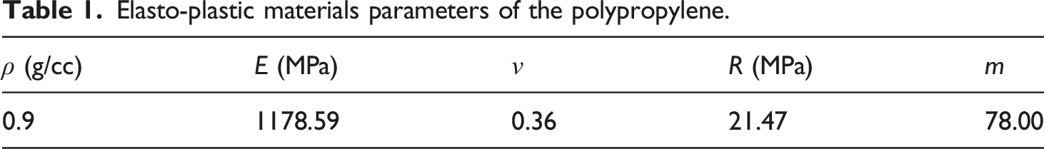
As shown in Figure 1, the obtained parameters allow a very good prediction of the tensile curve as the average deviation of the estimation thanks to the experimental curve is 2.02%. Elasto-plastic modelling of the PP mechanical behaviour and comparison with tensile test.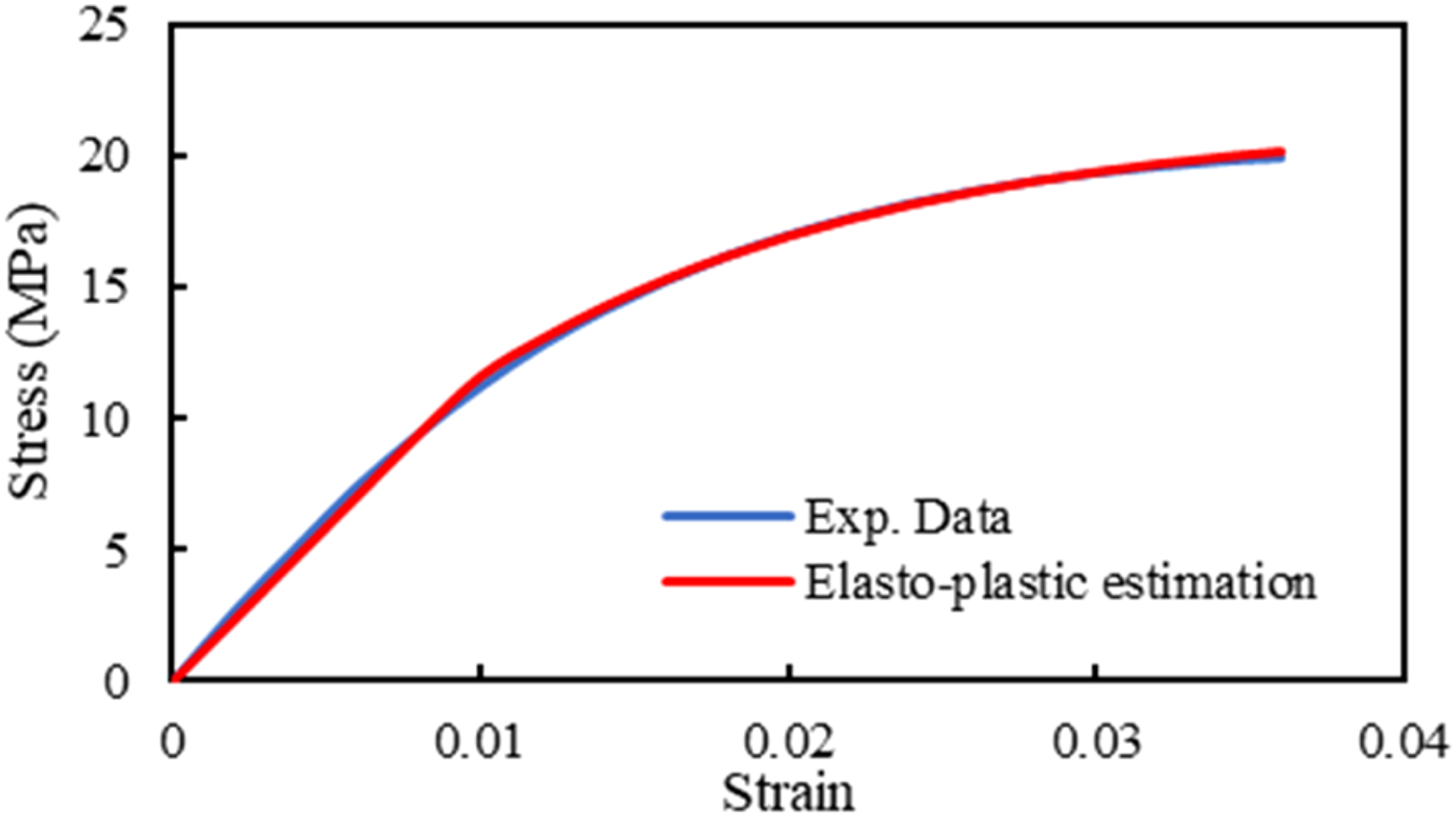
This kind of materials with a low glass transition temperature (about −15°C) 29 is known to presents a VE behaviour or VEVP behaviour when solicited at ambient temperature. Thus, even though the hypothesis of an EP behaviour leads to a very good approximation, a VE modelling allows a modelling more realistic, with a better description of the physical phenomena occurring in the material.
A multiplexing loading was thus conducted on the neat PP with DMA, in order to take into account the influence of viscosity on its mechanical behaviour. Even though DMA on PP was already performed in existing study, they presented a loading with a temperature ramp. 30 A multiplexing mode of loading dedicated to a multiscale modelling was, to the author’s knowledge, never performed before. The analysis allowed the obtention of VE parameters such as the storage modulus, the loss modulus and the Tan δ. The time-temperature equivalence was exploited in order to construct the master curve at a reference temperature with a horizontal shift. The temperature of reference was set at 30°C as the aim of this study is to perform some correlations with the mechanical behaviour of the composite obtained at that temperature.
The obtained master curves for each parameter are presented in Figure 2. Master curve of the PP of the (a) storage, (b) loss moduli and (c) tan δ.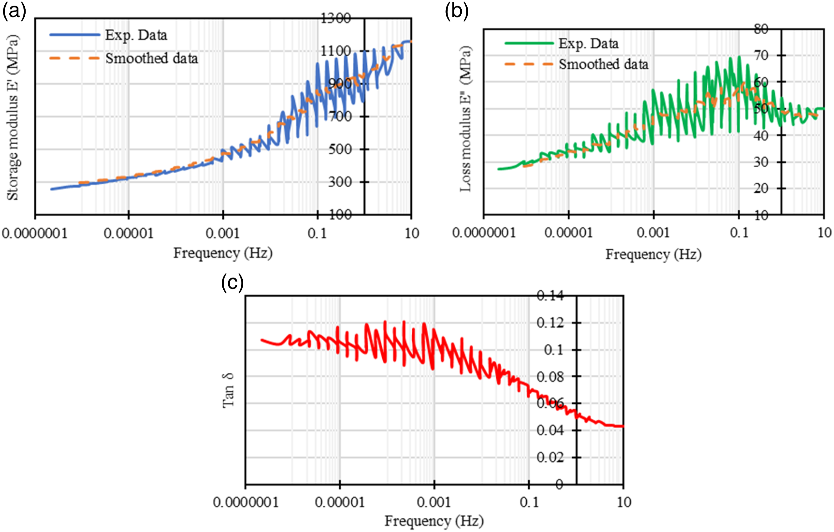
The smoothed data were obtained with a moving average method in order reduced the oscillations due to the viscoelasticity of the material, highlighted by the superposition method. It is worth noting that the storage modulus obtained at 30°C is equivalent to the Young modulus obtained on the tensile curve. At this temperature, the influence of frequency is reasonably negligible. These observations, more than validate the experimental data, validate the hypothesis that, in some conditions, the neat PP can reasonably be modelled with an EP approximation.
The other point of view, adding complexity but enhancing physical meaning of he modelling, is based on the storage and loss moduli and thus the viscoelastic behaviour of the polypropylene matrix.
The general formalism of viscoelasticity is based on the relaxation moduli, following:
As neat polypropylene can be considered as isotropic, the relaxation moduli can be expressed as a function of the time-dependent shear modulus
These moduli can be expressed as a function of well-known Prony series which are defined in the following way: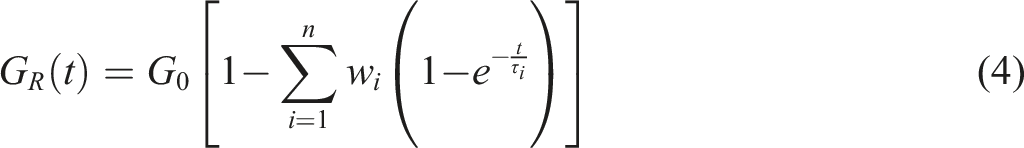
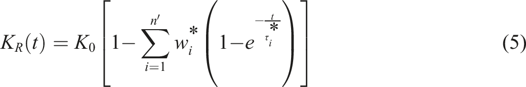
The best global accuracy was obtained for two terms of Prony series number, for a computed equivalent Young’s modulus presented in Figure 3. Viscoelastic modelling of the storage modulus of the PP.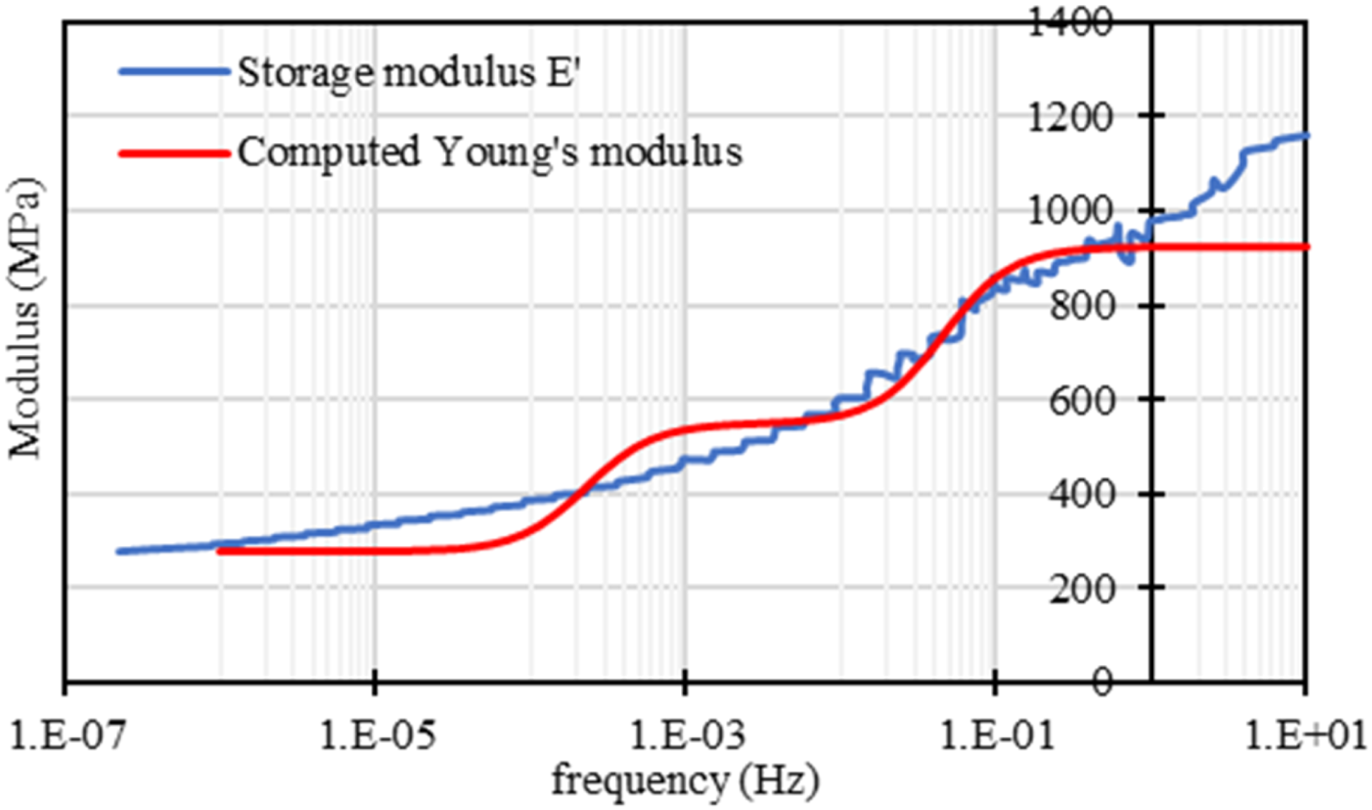
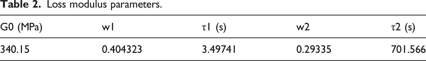
Loss modulus parameters.
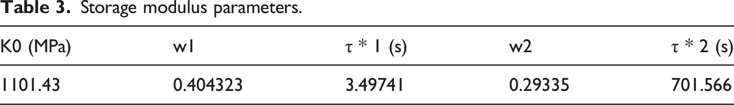
Storage modulus parameters.
The experimental storage modulus was shown to be identical to the Young’s modulus obtained with tensile tests. The VE modelling, however, introduce some error with the master curve of the storage modulus. This is a well known problem, more visible as the range of frequencies studied is large.31,32 Consequently, the VE modelling with Prony series can lead to good results and predictions for different conditions of time and/or temperatures, but can locally diverge from the experimental data, as it can be seen in Figure 3 for frequencies higher than 1 Hz.
Reinforcement mechanical behaviour
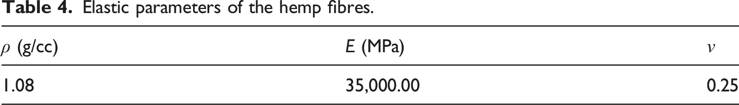
Elastic parameters of the hemp fibres.
Definition of the microstructure
As the studied composite is reinforced with short fibres and obtained with injection process, its microstructure is complex. It is thus very important to deal with the fibre repartition and orientation within the samples in order to be able to compare the results with the tensile tests. One way to evaluate the fibre orientation is to perform injection simulations. However, in academic and industry, it is common to rely on databases of materials obtained from suppliers. That kind of databases does not yet take into account complex fibre geometry. Generally, the synthetical fibres are considered as cylindrical, with an aspect ratio of 20 for short fibres.
In order to isolate the influence of the fibre geometry on the mechanical results, injection simulations were performed on the mould used to product the samples, the actual fibre orientation being then considered.
The PP data were obtained with the existing database, corresponding to the grade from Sabic™ used in the experimental study.
The parameters linked to the fibres are the one listed in Table 4, and the aspect ratio of the cylinders was fixed at 8. Indeed, it was shown that most of short hemp fibres used in the used compound present the same apparent aspect ratio, considering the average length and the dispersion in the geometry of the fibres. 18 As most of injection simulations are performed with cylindrical geometry of fibres, the aspect ratio was thus fixed to eight in order to be as representative as possible of the fibre geometry, with the existing methods. This aspect ratio was found in 18 by considering the actual length of the fibre, independently of the curvature of the fibre.
A mesh of 364,631 tetrahedral elements was used to define the mould and the simulation was performed with a mould temperature of 50°C, a melt temperature of 240°C and a filling time of 0.4057 s.
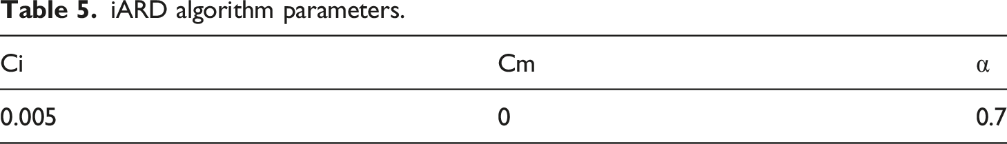
iARD algorithm parameters.
The estimated fibre orientation is presented in Figure 4. Fibre orientation in the injected specimens.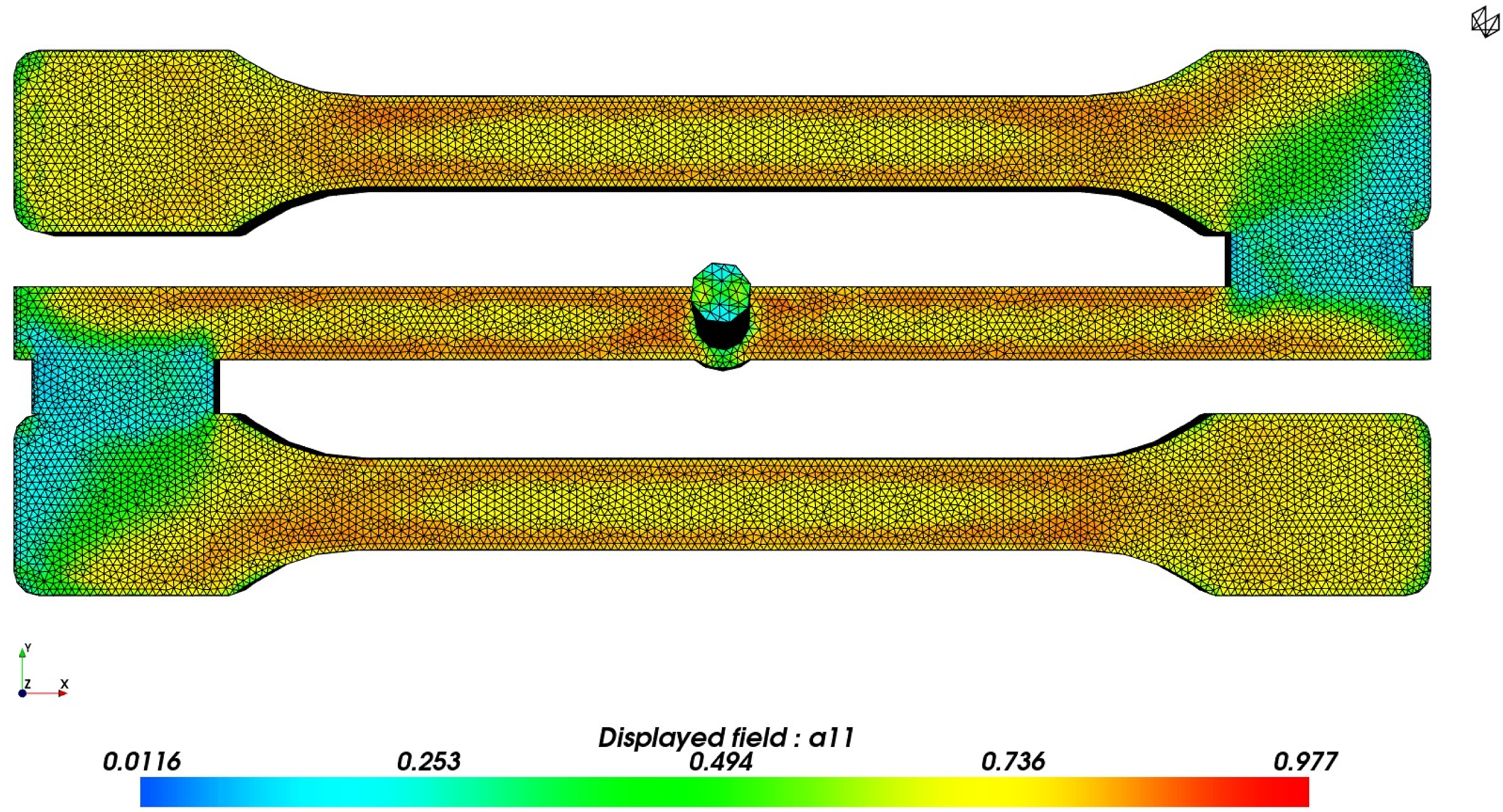
Figure 4 shows that there is a clear preferential fibre orientation in the longitudinal direction of the specimen. This can be easily explained by the mould geometry and the location of the injection gates. It is interesting to note that both specimens present the same orientation in their respective working length, allowing repeatable results.
The mechanical simulations were performed with a Representative Volume Element (VER), extracted from the injection simulation at the middle of the working length, as shown in Figure 5. Numerical extraction of the RVE.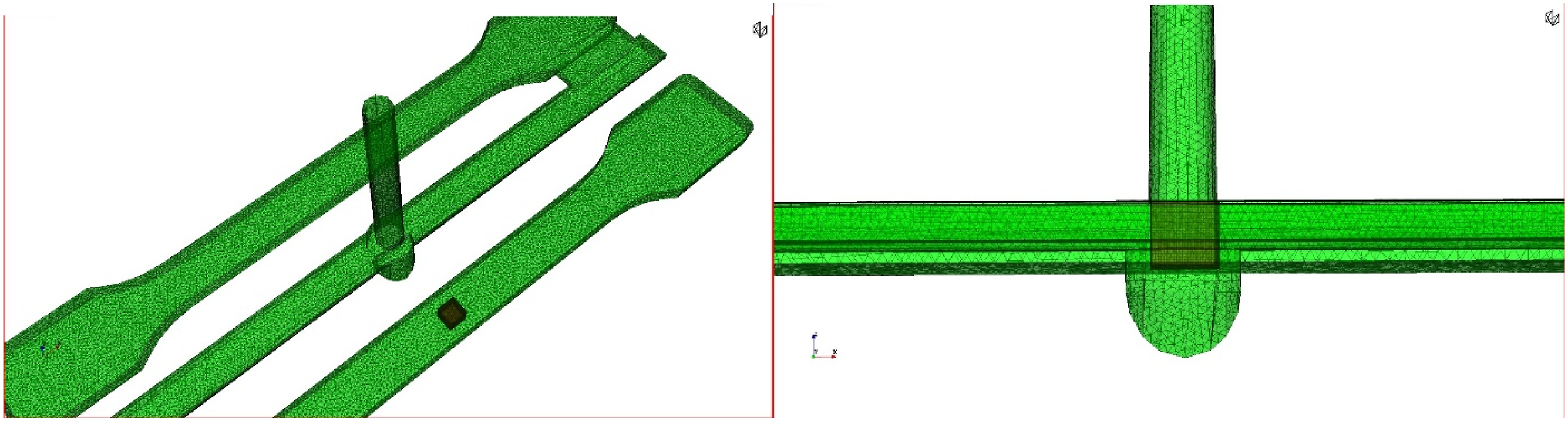
Mesh and boundary conditions
In order to simulate a tensile test, the simulation is strain controlled at a quasi-static speed, fixed at 1.10−3 s−1. Then, a periodic boundary condition was applied to unsure that the flux of the field variable is periodic with respect to the faces of the volume element. 34 Also, as no damage is taken into account in this study, the interface between the fibre and the matrix is considered as perfect.
A tetrahedral meshing was applied on the RVE, with approximately 85 000 elements in order to ensure reliable results. As no damage or interface is taken into account, the applied meshing can be considered as fine. An example of a generated and used mesh is presented in Figure 6: Mesh of a studied RVE.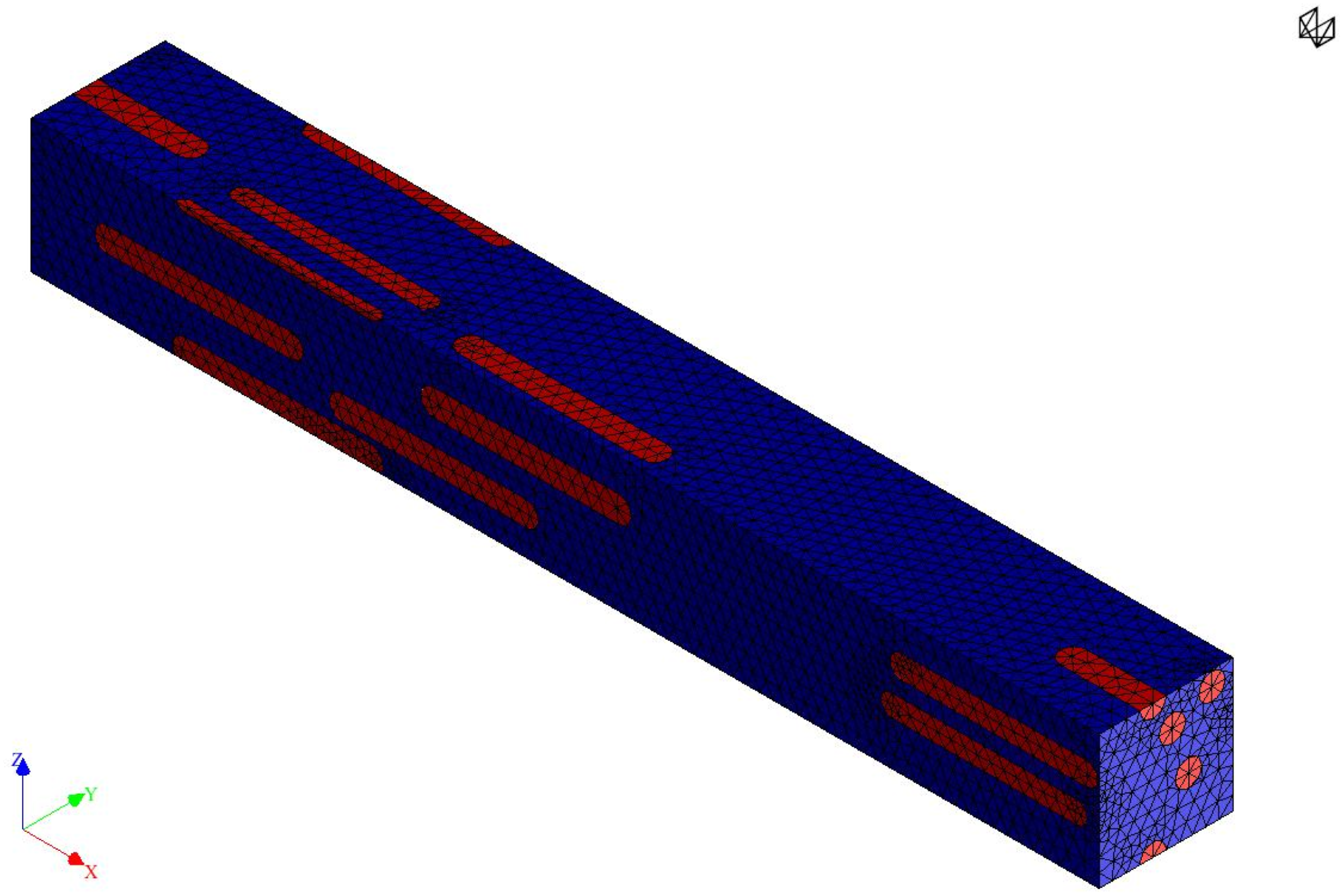
The RVE defined from injection simulation was meshed with a tetrahedral meshing with approximately 86 000 elements du to the complexity of the microstructure induced by injection. The RVE generation, meshing and loading were simulated with Digimat© software.
Estimation of the composite’s mechanical behaviour
All of the simulated configurations were compared to experimental data obtained on tensile curve of the PPHF20. The tests were performed in the same conditions than the ones used for the neat PP. Figure 7 shows the average tensile curve on the reinforced PP, without error bar as the tests are simple and repeatable. Tensile tests results of neat and reinforced PP.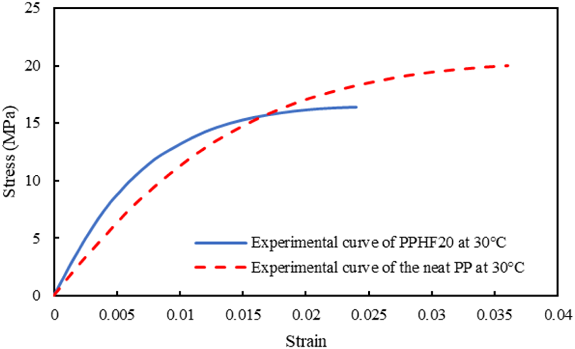
Figure 7 shows that the presence of hemp increases the stiffness of the PP. A diminution of the ultimate tensile stress is observed on the composite with respect to the neat material, showing the influence of damage propagation. Even though this phenomenon was experimentally investigated, the consideration of damage and fibre debonding would requires complex characterization and modelling to be quantified for natural fibres and is beyond the aim of this study.11,17,18,25,28,35 The present study hence focuses on the elastic properties to avoid the influence of this phenomenon on the results. The results of the simulations presented in the next sections were thus compared to the experimental data through the analysis of the obtained Young moduli.
Influence of the fibre orientation
First of all, an investigation of the fibre orientation was performed, considering the common approximation of the geometry as a cylinder. All generated microstructures were generated with an aspect ratio of eight to be as representative as possible of the apparent aspect ratio of hemp fibre. Three configurations of orientations were studied. As shown in Figure 4, the fibres are well aligned with the direction of loading. The first configuration studied was thus the one with the hypothesis of fibres perfectly aligned with the direction of loading. This configuration, very optimistic, represents the upper limit of the studied cases. The second configuration is a random orientation of fibres. This hypothesis can be made by the curved geometry of the fibres, which can lead to a quasi-homogeneous reinforcement effect. Finally, the last configuration of orientation can be considered as the most accurate as it relies on the fibre orientation tensor of the RVE, obtained with injection simulation.
All generated microstructures reached the actual volume fraction of 17.3% corresponding to the PPHF20 within a tolerance of 0.03% of deviation from the fixed one, and are presented in Figure 8. Studied RVE with (a) longitudinal fibre orientation (b) random 3D fibre orientation and (c) simulated fibre orientation with injection simulation.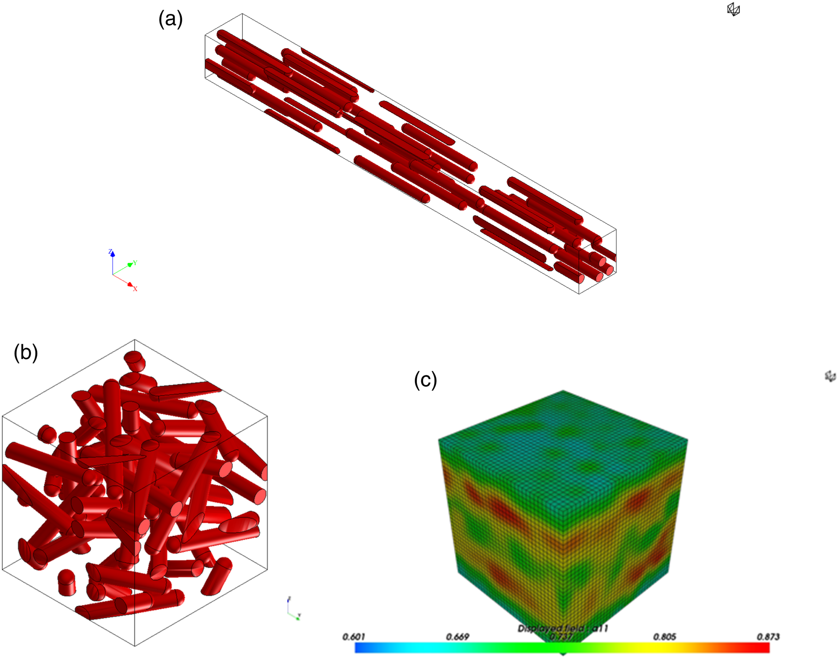
Figure 8(c) clearly shows the complexity of the fibre distribution and orientation as capillarity effect is present on the mould surface and, more importantly, the microstructure clearly presents a core-shell microstructure, characteristic of the injection moulded composites.
As this study focus on elastic properties of the composite and for the sake of comparison, the properties of the PP matrix are assumed elastic first.
The results of the simulated tensile tests on the different microstructures and the comparison with the experimental tensile tests are presented in Figure 9. The results presented in Figure 9 are obtained with the same experimental data and fibre geometry, as also presented in Figure 8. Influence of fibre orientation on the stiffness of the composite and comparison with experimental data.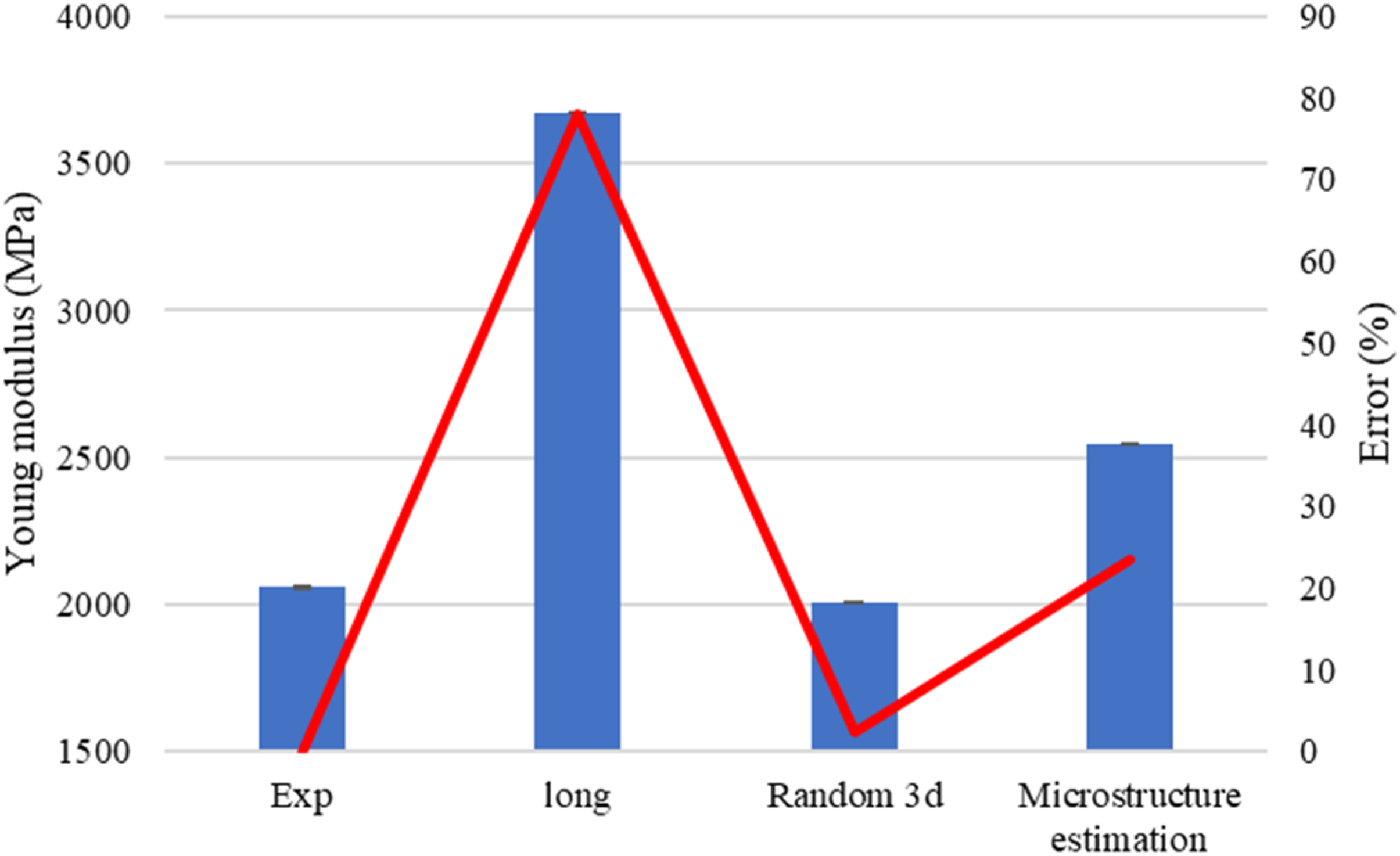
It can be seen in Figure 9 that, without surprise, the fully aligned configuration with respect to the loading direction provides the highest stiffness. However, this estimation is far from the actual stiffness obtained with tensile tests. The hypotheses of a longitudinal orientation and cylinder-shaped fibres together cannot properly describe the mechanical behaviour of such composite.
A study of the influence of the aspect ratio efficiency can be performed with the longitudinal fibre orientation configuration. In this way the ‘ineffective’ loading of fibres over their stress transfer length can be taken into account. Since the fibre is only partly utilised in the case of a short fibre composite, these effects have to be taken into account when modelling the mechanical performance of such composites, as it was shown by Cox. 36
Considering elastics properties of each component, as it is in this study, and a fully straight and aligned configuration, the fibre efficiency factor is about 45%, considering a geometrical packing arrangement similar to the one obtained for a PP reinforced with glass fibres. 37 This means that, even for a purely longitudinal orientation and straight fibre that is the best configuration possible, the fibre is barely reinforcing the matrix. Hence, longer fibres could help the optimisation of the reinforcement effect.
The consideration of the actual core-shell microstructure allows a better consideration of the fibre orientation. The considered geometry remains, however, cylindrical. This hypothesis leads to a deviation of 25% with respect to the experimental data. This result indicates that the curved geometry of the fibre leads to a repartition of the stress which is inhomogeneous and less effective than a cylinder-shaped fibre. This is an important point as the injection simulations performed in industry are generally performed with such a hypothesis. The obtained error can thus be a brake to the development of short natural fibre reinforced materials if no alternative is provided. Moreover, the geometry of the fibre clearly shows an influence on the mechanical properties of the material but can also influence the orientation tensor. The obtained orientation tensor, obtained with cylindrical fibres, can also shows some deviation with respect to the real fibre orientation within the specimen.
Further injection simulations should then be performed with different fibre geometries in order to study the influence of the fibre geometry on the fibre orientation in the material.
The most accurate results are obtained with a random distribution of fibre in the RVE. The aspect ratio fixed to the actual apparent aspect ratio of the fibre and the random orientation allows the best configuration to simulate the curved geometry and the induced 3D reinforcement effect. This configuration is the only one acceptable as the obtained error is about 3%.
The random 3D distribution was then defined as the reference to study more in details the influence of the fibre geometry on the mechanical behaviour of the composite, with this orientation.
Influence of the fibre geometry
The different geometries investigated were all curved cylinders, in order to approach the real form of the short hemp fibres. The curvature of the fibres was controlled by two parameters: kappa1 and kappa2, whose values typically ranges between 0 and 100. Kappa1 controls the reliability to the main fibre orientation, meaning that the orientation vector between two fibres is close to the prescribed fibre orientation. The higher the value, the higher the probability to have all the orientation vectors equal to the prescribed fibre orientation hence higher the probability to have straight fibre. Kappa2 controls the reliability to the last orientation. Hence, the higher the value, the higher the probability to have purely bended fibre. The lower the value of both Kappa1 and Kappa2, the lower the probability to respect the prescribed orientation tensor. 34
The influence of each Kappa on a fixed orientation can be seen in Figure 10. Influence of Kappa parameters on the generation of fixed orientation RVE with (a) Kappa1 = 100 and Kappa2 = 0 and (b) Kappa1 = 0 and Kappa2 = 100.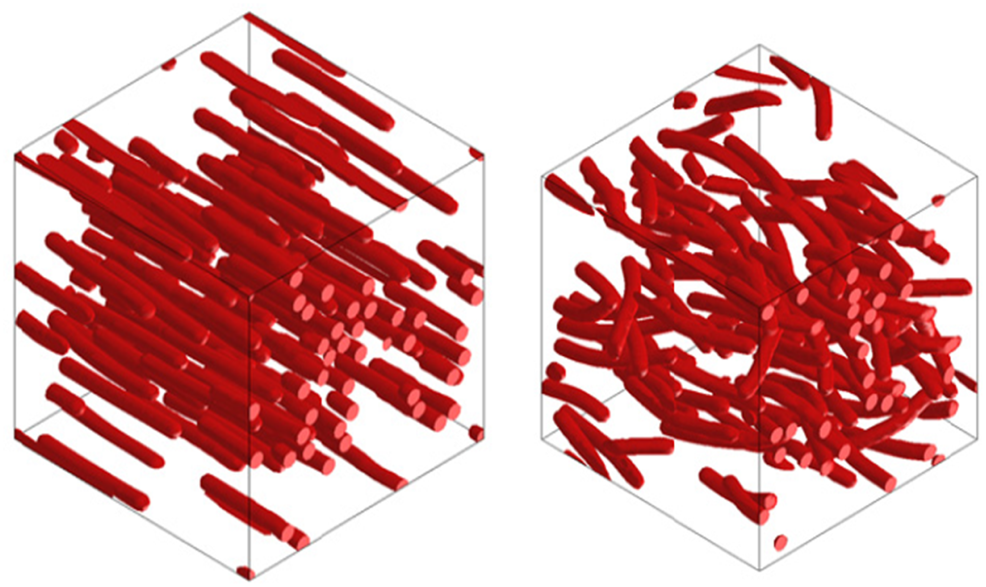
Examples of studied microstructures relevant for the are presented in Figure 11. RVE generated with couples of kappa1 and kappa2 parameters (a) 1/1 and (b) 100/100.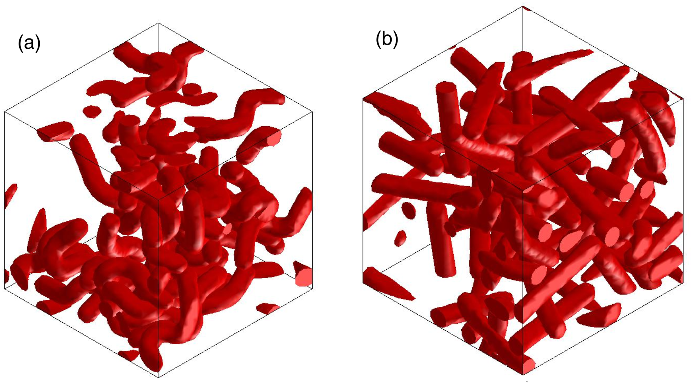
Due to the complexity of the microstructure induced to the curvature of fibres, the meshed was refined, leading to approximately 90 000 tetrahedral elements.
A synthetization of the results obtained with different couples of kappa1/kappa2 parameters are presented in Figure 12, as well as the comparison with the cylinder random 3D estimation and with experimental data. Influence of fibre curvature on the stiffness of the composite and comparison with experimental data and precedent approximations.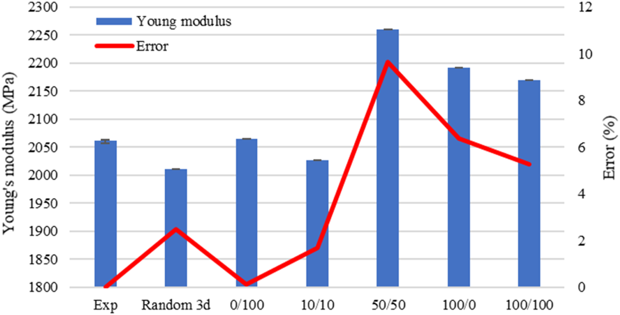
It can be seen in Figure 12 that all of the approximations present an error under 10%, meaning that all of the assumptions are acceptable. However, only two approximations provide better results than the random 3D hypothesis obtained with cylindrical fibres.
Those configurations are obtained with couples of parameters 10/10 and 0/100, the best being the latter. In both cases, kappa1 is low, meaning that the curvature of the fibres is so high that the equivalent global orientation is a bit different from the wanted one. However, the imposed fibre orientation being “random 3D,” this means that there is a little sensibility to fibre orientation, as suspected from the fibre orientation presented in Figure 4. This sensibility can reasonably be neglected for the studied injected samples as the difference between the straight random 3D and 10/10 configurations is about 1%.
The 0/100 couple means that the probability to have a straight fibre is the lowest. The fact that the best results are obtained with this configuration significates that the curvature of the fibre, and thus its geometry, presents a more important influence on the mechanical behaviour of the composite than the fibre orientation.
The random 3D configuration, with straight or bended fibres, provide the best results. If it can be a reasonable simplification for the study of tensile properties of standard specimens, it can be too optimistic for real injected parts. Moreover, even though the generation of random microstructures led to repeatable results in this case where an RVE is definable, it can be different on real injected parts.
A modelling process, whatever its complexity, cannot provide results leading to a 100% correlation. Also, the experimental data being obtained on dog-bone specimens and the simulation being computed on RVE, a comparison with the actual RVE of the specimen is then proposed in the next section, in order to have the best comparative study possible and confirm the first conclusions.
Correlation with real microstructure
It was shown that the curvature of the fibre is important to estimate the composite behaviour. However, the consideration of a cylindrical shaped, even curved, represents a simplification as the fibres present a structure more complex. Hence, the previous simulations were compared to an FFT computation on an RVE obtained by X-ray tomography performed on the tested specimen, in order to provide the best reference possible.
X-ray tomography allows the study of the actual microstructure of the material, with the real fibre geometry and orientation. The RVE was reconstructed with the software ImageJ™, with a volume of 300 * 300 * 300 pixels, and can be considered as representative as the obtained volume fraction is 17%, which corresponds to a mass fraction of 20%, and is identical to the volume fraction of the previously studied RVEs. A representation of the reconstructed RVE is presented in Figure 13. Reconstructed RVE from X-ray tomography.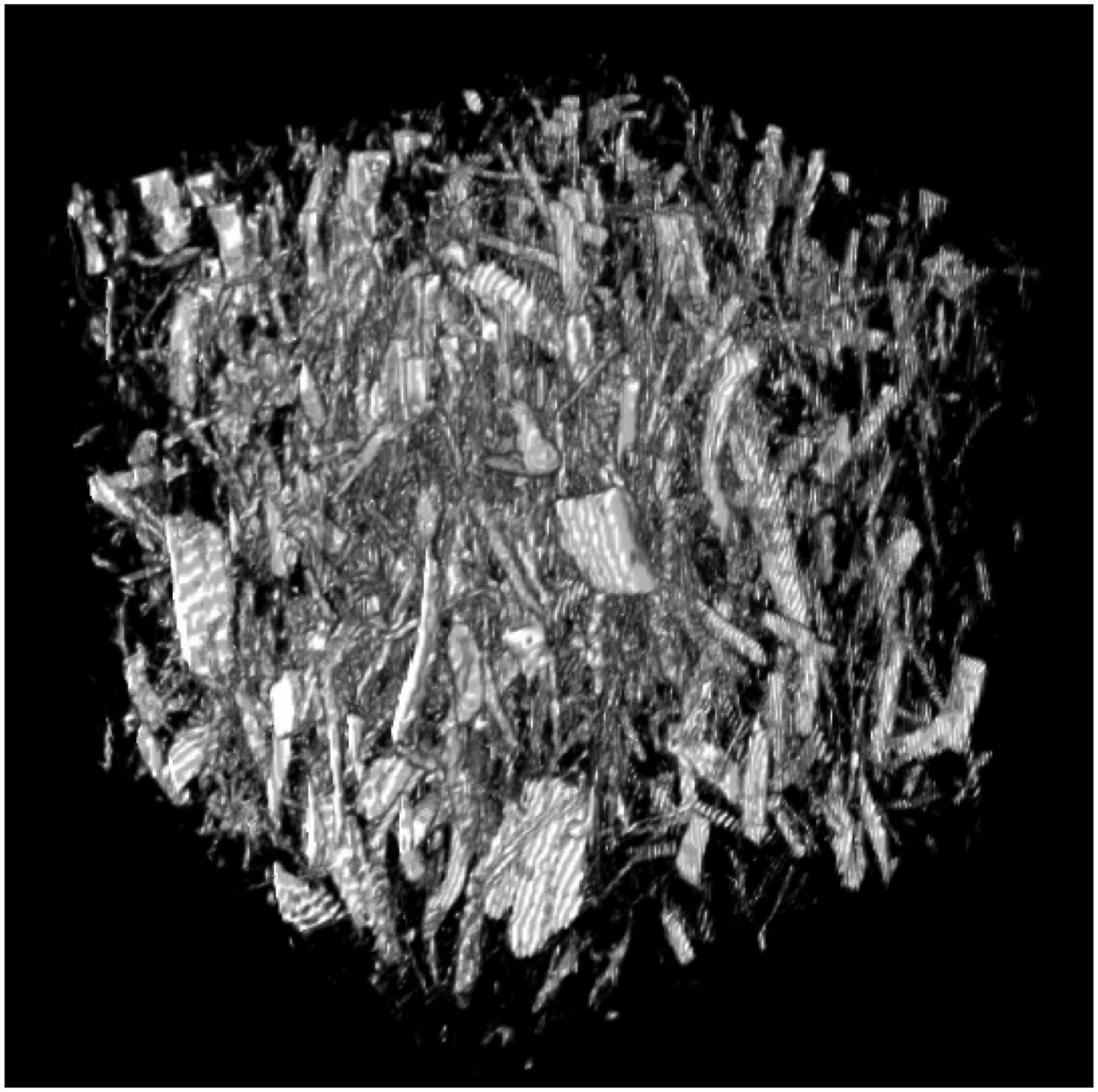
As the average width of the fibre is about 30 μm, the resolution of 6–7 μm allows the consideration of the global structure of the fibre. This resolution is satisfying in this study as no fibre/matrix decohesion is considered in the simulations.
The complexity of the fibre geometry can be seen in Figure 13. The pattern of the fibre is also not repeatable. Then, if some of them can be modelled as curved-cylinders, some of them are flattened. This method is thus the only one taking into account the different curvatures and shapes of the fibres.
A closer look can also confirm the precedent assumptions, as the RVE presents a preferential fibre orientation, but with a reduced effect due to the complex geometry of fibres, as shown in Figure 14, and is in line with the simulated fibre orientation and the random 3D approximation. Fibre orientation in the reconstructed RVE.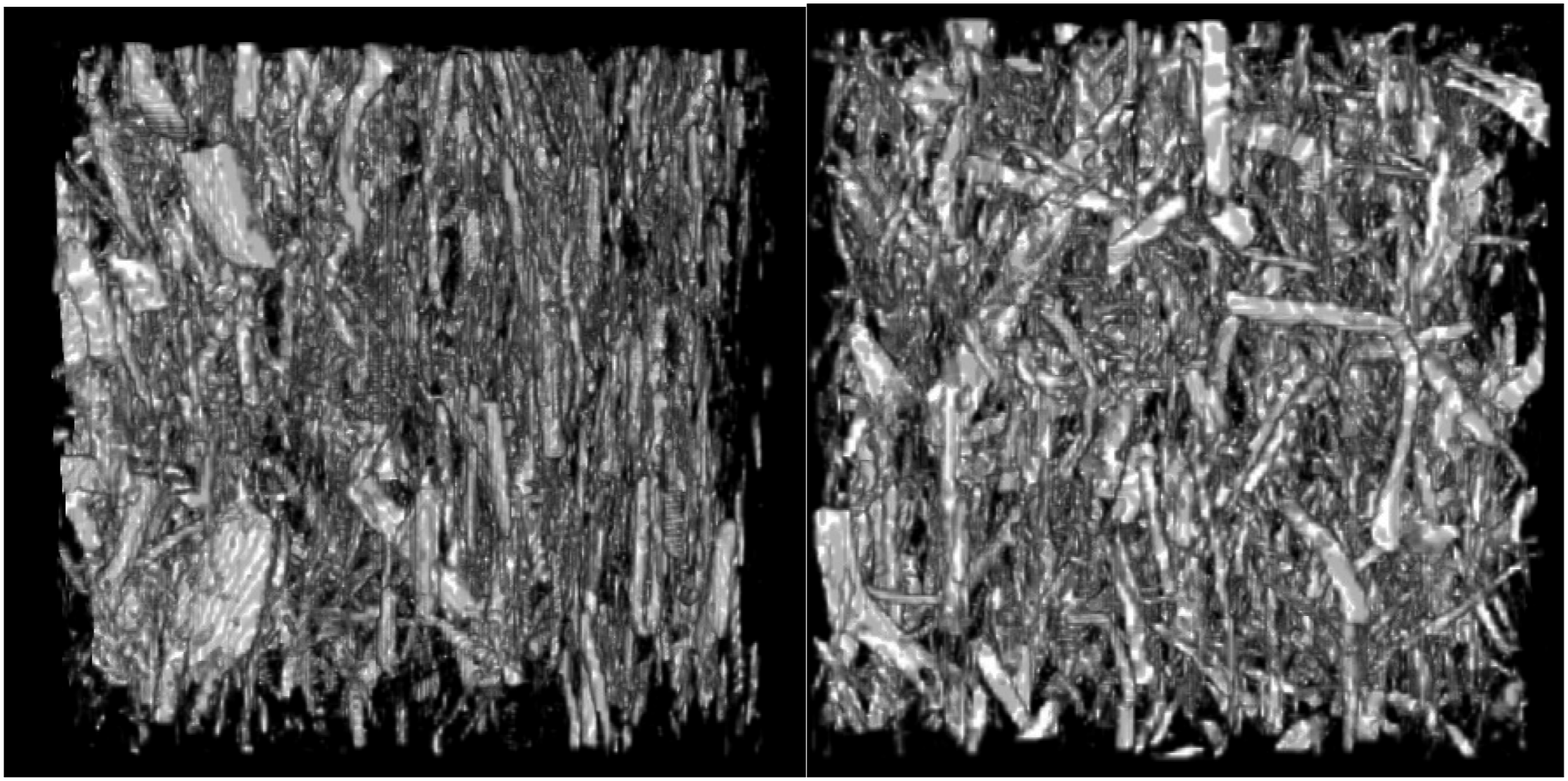
In order to perform FFT analysis on the RVE, the reconstructed volume was modelled and meshed with 3 375 000 voxels, allowing a good modelling of the complex geometry of fibres, while keeping the 17% of volume fraction.38–40 The modelling and the mesh are presented in Figure 15. Modelling and meshing of the reconstructed RVE.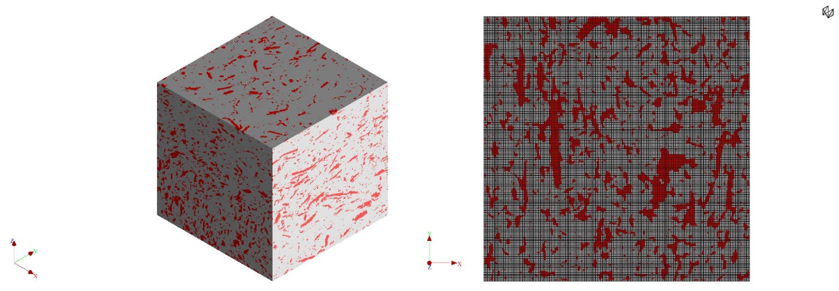
The loading was defined as the same as the one applied on the previous microstructures. FFT methods allowing complex simulations with a reduced computation time, both elastic and viscoelastic approximations of the mechanical behaviour of the matrix were investigated.
As the RVE obtained with X-ray tomography represents the one of the tensile specimens, the simulations were performed in three directions in order to investigate the reliability of the precedent hypothesis made on the equivalent random 3D approximation. Due to the geometry of the mould, it is also the only way to explore the eventual anisotropy of the injected and tested specimens. The results are presented in Figure 16. Influence of loading direction on the stiffness of the composite.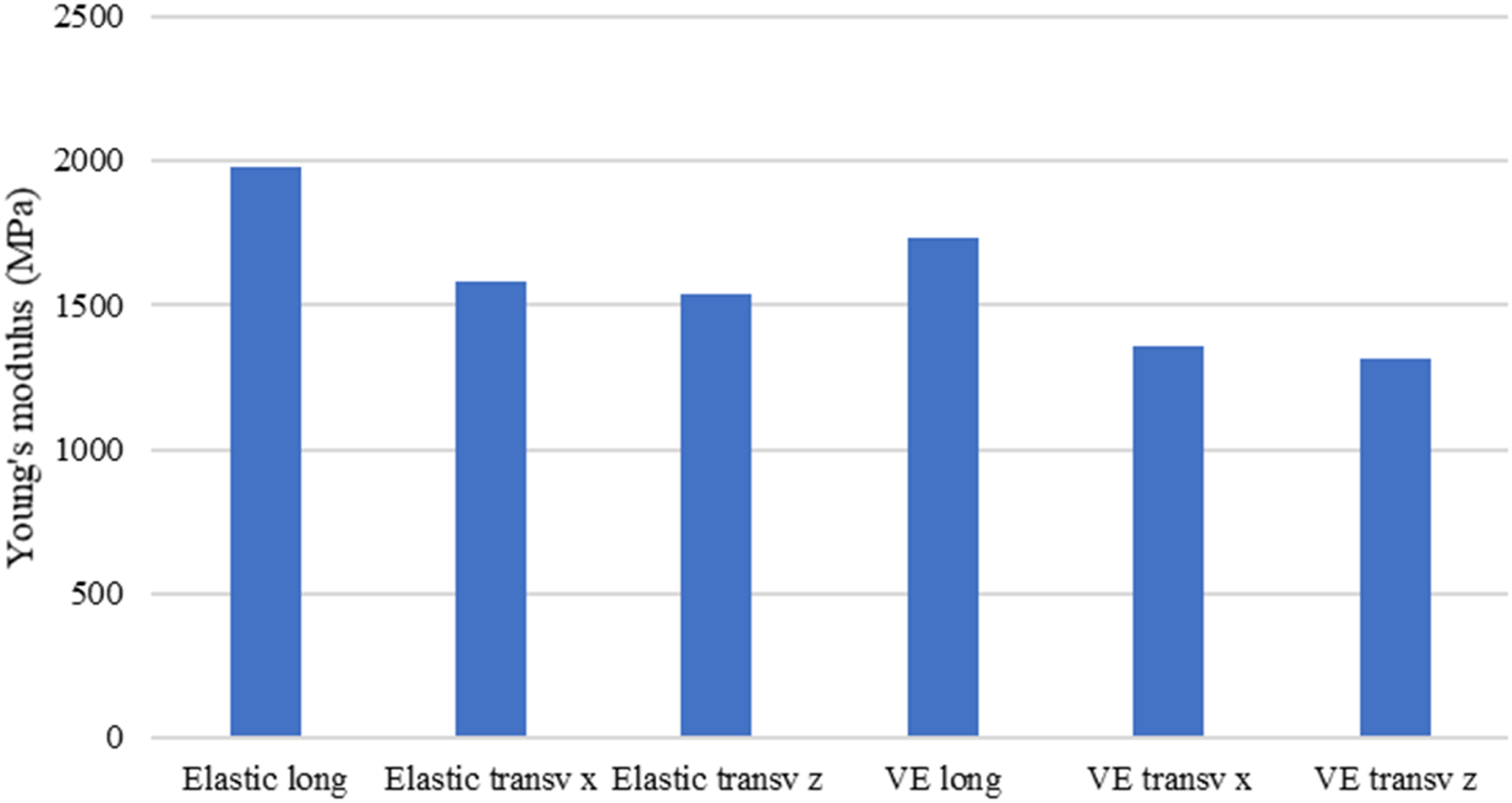
Figure 16 shows that a little effect of fibre orientation due to the injection process is visible, but remains limited. Even though Figures 4 and 13, however, show that the fibres are well aligned with the loading direction, this orientation leads to a limited effect on the mechanical behaviour of the material, which can be defined as transversally isotropic.
This is thus confirming that the curvature of the fibre is the predominant parameter leading the mechanical behaviour of the composite, more than the fibre orientation. This result also tends to validate the random 3D approximation.
The results obtained with a viscoelastic approach are similar but below the estimations with a purely elastic modelling of the PP matrix.
A synthesis of the different configurations is presented in Figure 17, considering straight and curved fibres, different fibre orientations and both elastic and viscoelastic considerations. Influence of matrix modelling, fibre orientation and curvature on the stiffness of the composite and comparison with experimental data.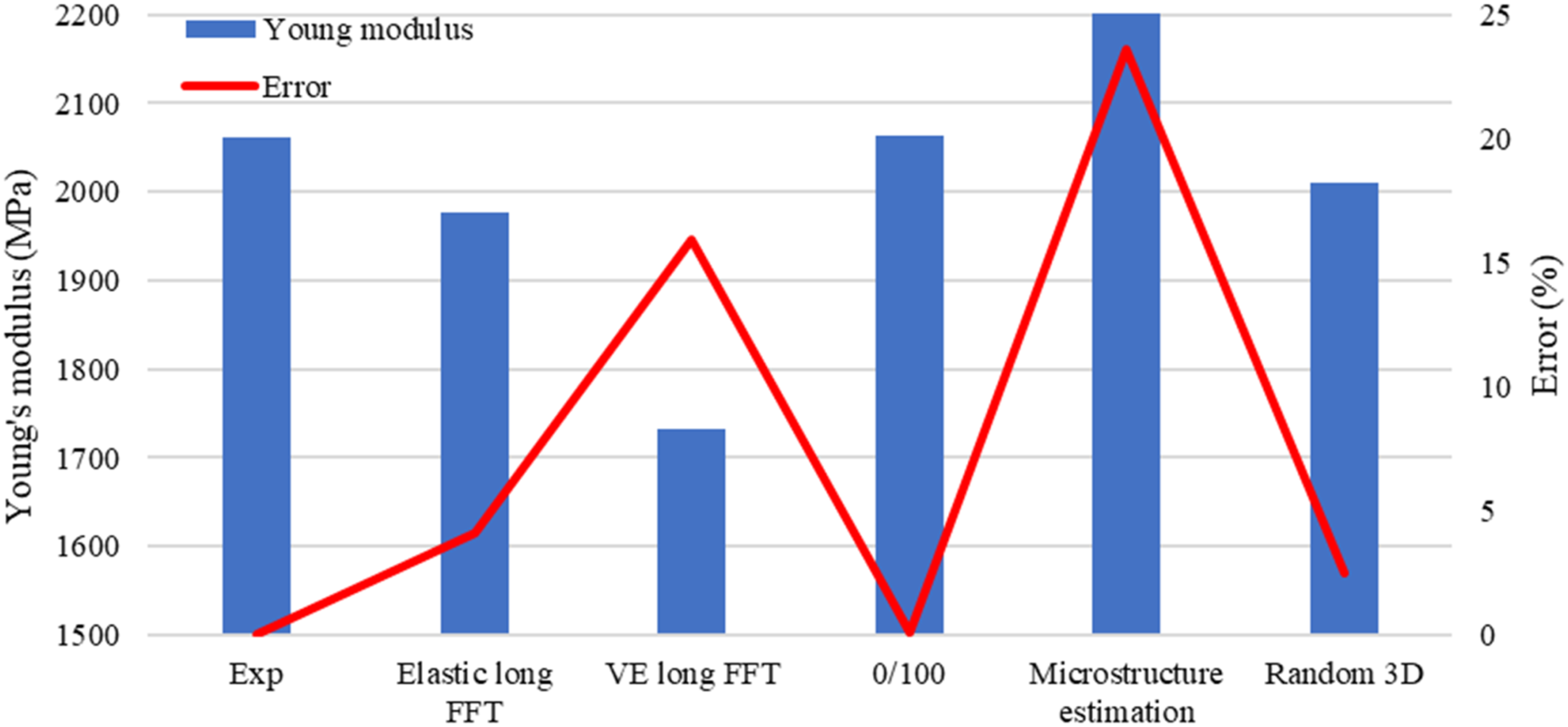
First, it can be seen in Figure 17 that, as also shown in Figure 16, the viscoelastic modelling of the matrix leads to an underestimation of the actual stiffness of the composite. This can be explained by the Prony series estimation which “oscillates” around the master curve of the storage modulus, as shown in Figure 3. At the frequency studied here, corresponding to a temperature of 30°C, the modelling underestimates the experimental storage modulus, explaining the differences observed in Figures 16 and 17. However, the results remain at the limit of the acceptable, with an error of 16%, and the use of viscoelastic modelling can become unavoidable for estimations of the mechanical behaviour at high temperatures and/or over a wide range of frequencies.
The error observed on the viscoelastic modelling has also to be relativized, as the same simulation performed with FFT but with elastic approximation led to an error of 4% with respect to the experimental data. The fact that even an RVE obtained with X-ray tomography leads to an error of 4% shows the complexity of the problem. The results remain very accurate.
The use of couple X-ray tomography and FFT computations can be very difficult in an industrial context, and/or for the study of structural parts without RVE. Hence, as it was shown in Figures 9, 11 and 16, the best approximations are provided by a random 3D orientation of the curved or straight fibres.
The preponderant importance of the curvature of the fibres, more than their orientation which, considering their geometry, leads to a transversally isotropic mechanical behaviour, can be partially approximated with random 3D generated RVE.
This approximation allows a considerable simplification of the problem, allowing further investigations of the material behaviour, as long as the notion of RVE remains.
From an applicative point of view, another outlook would be to focus on the geometry of the reinforcement and the optimisation of the obtention process of the composites. Most of commercial grades reinforced with natural fibres contain particles or fibres with a low aspect ratio. Even though the curvature is a major problem to take into account, the length of the reinforcement is also to be improved. Indeed, as it was shown in Figure 9, even with straight and fully aligned fibres, the efficiency of the reinforcement is about 45%. The obtention of composites with controlled aspect ratio distribution higher than nine would allow to reach the 50% of fibre efficiency. The obtention of an aspect ratio of 20 would thus help the design of parts as it would be similar to synthetic fibre, while improving the reinforcement efficiency.
Conclusion
In the present study, simulations with FE and FFT methods were carried out on short hemp fibre reinforced polypropylene in order to find the best approximation of the microstructure. To do so, the simulations were compared to experimental data obtained with tensile tests. For the numerical homogenization, the PP matrix was modelled with a purely elastic and viscoelastic behaviour.
The RVE obtained with X-ray tomography and with injection simulations showed a global fibre orientation strongly aligned with the loading direction. However, the fibre orientation, contrary to synthetic fibre, presented here a limited influence on the mechanical behaviour.
It was then shown that the predominant parameter leading the mechanical behaviour is the geometry of the fibre. Dealing with curved fibres being complex for simulations performed in industrial or academic context, it was shown that the transversally isotropic behaviour of the material can be approximated by a random 3D fibre orientation. Indeed, the isotropization of the mechanical behaviour due to the curvature of the fibre compensates the effect of fibre orientation and can be approximate with this random 3D distribution.
This approximation can, however, show some limits in the case of structural parts, where no RVE can be defined. In this case, and an outlook of this present work, would be to perform injection simulations with curved fibres, in order to evaluate the influence of the geometry of the fibre on the orientation tensor and refine the stiffness prediction with injection simulation.
The modelling of the storage modulus of the PP matrix with Prony series showed a slight underestimation of the stiffness of the material. It was however shown that computations with this complex behaviour of the matrix is possible and allows further investigations for different environmental conditions, such as high temperatures, high and low frequencies and on aged samples.
In the present study, conducted at 30°C, it was shown that an elastic approximation is acceptable, lightening the computations, creating an ideal configuration to investigate other problematics linked to the microstructure. Indeed, another outlook of this work is to investigate the inelastic behaviour of the material by implementing damage phenomenon, which can be occurring in the matrix, the fibre and evaluate the fibre/matrix debonding. A deeper attention should also be given to the obtention process, in order to take into account the crystallinity of the PP and the cooling rate dependence on it as well as on the residual stresses in the matrix, the fibres and the interphase. 41
Footnotes
Author contributions
Conceptualization, methodology, investigation, writing—original draft preparation, writing—review and editing, and visualization: Quentin C.P Bourgogne
Declaration of conflicting interests
The author(s) declared no potential conflicts of interest with respect to the research, authorship, and/or publication of this article.
Funding
The author(s) received no financial support for the research, authorship, and/or publication of this article.
Data availability statement
Data are available on request.