
Abstract
An ear-flow front is discovered in the industrial practice of injection molding, especially for fiber-reinforced composites; the advance of the flow front in the center of the cavity is obviously slower than at the edges. To date, such a peculiar flow has not yet been predicted theoretically or computationally and is beyond the predictive capabilities of existing commercial computer aid design (CAE) packages for the injection molding process. Recently, the GNF-X (Generalized Newtonian Fluid eXtended) model of weighted shear/extensional viscosity has been incorporated availably in state-of-the-art predictive engineering software of the 3D-CFD (three-dimensional computational fluid dynamics) framework to show the extension-induced vortex growth in contraction flows of polymer melts. Through 3D-CFD coupled with GNF-X in injection molding simulations, it is significant to demonstrate the importance of extensional viscosity on the ear-flow formation in relation to the weighted viscosity and extension fraction for long-branched and fiber-filled polymer materials. In addition, one can point out that the ear-flow front probably occurs in fast filling conditions for anisotropic fluids.
Keywords
Introduction
In the industrial practice of typical injection molding for polymer melts, a peculiar ear-flow is always found in which the advance of the flow front in the center of the cavity is obviously slower than at the edges. The primary feature of the ear-flow front is the preferential progression along the edges, as schematically shown in Figure 1. The used fiber-filled polymer composites1–5 most often form the ear-flow front. These practical problems urgently need clarification for the industry’s benefit. However, rheological research has scarcely explored the formation of the ear-flow front. Although some works6,7 previously considered the shear-heating induced temperature effect at the mold surface on the ear-flow front, there is no significant finding with theoretical discussion and deduction. Schematic of ear-flow front in filling stage of a typical injection molding.
For exploring the nature of the ear-flow front, using the viscoelastic (VE) constitutive equations offers a good direction. Most VE fluid models are performed in 2D (two-dimensional) flow calculations,8–10 but the predictive subtle flow fronts are invisible. There are few computational rheological researches on 3D-VE (three-dimensional viscoelastic) flow simulations,11,12 and no ear-flow has been found. Previously, Moller and Lee 13 investigated effect of extensional viscosity on flow front progression in injection molding for unfilled and glass fiber-filled polypropylenes. According to the early experimental study of Laun 14 for short glass fiber-reinforced thermoplastics, the anisotropic effect of fiber orientation greatly increases the extensional viscosity. Recently, Tseng et al.15–17 performed that numerical predictions of fiber orientation and fiber concentration are in agreement with related experimental data for injection mold fiber composites. Significantly, Favaloro, Tseng, and Pipes18,19 derived that the flow-fiber coupling model of informed isotropic (IISO) viscosity is a function of the rate-of-deformation tensor and fourth-order fiber orientation tensor. The use of the IISO flow-fiber coupling model is to simulate anisotropic flows in the compression molding of fiber composites, as well as the ear-flow front in the injection molding. Unfortunately, IISO can only be used for fiber-filled polymer composites, not for neat polymers in the absence of additive fibers.
In the past, many researchers14,20 have focused the effect of extensional viscosity on the flow behaviors for polymer melts and polymer composites. Recently, for a inhomogeneous contraction flow, Tseng 21 proposed the weighted shear/extensional viscosity, namely, the GNF-X (Generalized Newtonian Fluid eXtended) constitutive equation. The GNF-X model has the potential to show vortex growth in the 3D entry flow simulations for an LDPE (low-density polyethylene) melt; 22 the predictions of vortex sizes are in good agreement with related experimental data.21,22 Showing the extension-induced vortex formation is significant. 21 Overall, the GNF-X model is much more stable in computations over a wide range of Deborah numbers. Furthermore, Tseng23–25 continued to improve the White-Metzner constitutive equation of viscoelastic fluids coupled with the GNF-X weighted viscosity model and the Dinh-Armstrong fiber suspension model.
Extensional viscosity is often a foreign concept in classical fluid mechanics, and hence its importance in viscoelastic fluid mechanics is stressed.26,27 After reviewing the related literature above, one can surmise that the ear-flow front is induced by the effect of extensional viscosity for anisotropic materials. The GNF-X model of weighted shear/extensional viscosity has been incorporated availably in state-of-the-art predictive engineering software of the 3D-CFD (three-dimensional computational fluid dynamics) framework.21,22 Through 3D-CFD coupled with GNF-X, the primary objective of the present study, therefore, is to demonstrate the effect of extensional viscosity on the formation of ear-flow front for anisotropic fluids of long-branched polymer resins and fiber-filled polymer composites. In addition, the fast/show flow rates and the isotropic/anisotropic fluids are examined herein.
Theoretical background
The actual flows of complex polymeric fluids are complicated in various geometric channels. The polymer processing is a highly nonlinear subject, as the material properties are dependent upon both flow and temperature conditions. For completeness, the governing equations of fluid dynamics, including those on continuity, motion, and energy, are addressed:


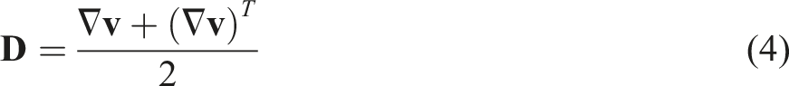
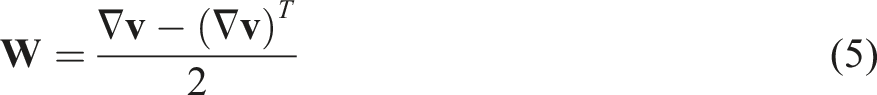
Among the governing equations above, an expression of the stress tensor
GNF shear and extensional viscosity
The generalized Newtonian fluid (GNF) model28–31 of shear viscosity describes the mathematical relationship between the tensors

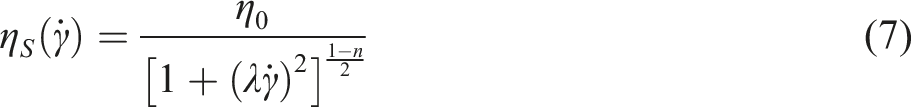
The flow curves of shear viscosity dominate the flow behaviors of a variety of materials. Commonly, the Carreau model,
29
a type of the GNF shear viscosity model, is used to fit experimental viscosity data:
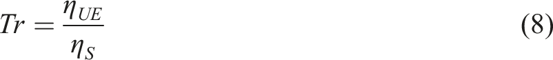
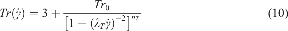
In rheology, the Trouton ratio Tr is extensional viscosity over shear viscosity.28,32,33 For the uniaxial extensional viscosity
For the isotropic Newtonian viscosity,
32
the Trouton ratio ideally equals 3, namely, Tr = 3. Thus, Tr >> 3 implies the anisotropic viscosity. However, it is difficult to directly model the extensional viscosity via a mathematical relationship. Recently, Tseng
21
proposed the Trouton ratio function for an interrelationship between nonlinear shear viscosity and nonlinear extensional viscosity,

GNF-X weighted viscosity
Recently, Tseng
21
derived the weighted shear/extensional viscosity


However, Park 34 commented the GNF-X model in which those so-called principal shear and extension rates cannot represent the shear and extension rates correctly. Therefore, Tseng 35 have sufficiently demonstrated that the GNF-X numerical algorithm can decompose exact shear and extension rates validated in the analytical center-gated disk flow. Significantly, Wen et al. 36 performed the non-isothermal GNF-X flow simulations to estimate the extensional viscosity for various polymer melts.
Basically, the GNF-X weighted viscosity is similar to the early Schunk-Scriven experiential model of a linear combination (or arithmetic mean) of the two type-Carreau-type shear and extension viscosities. 37 Differently, the Schunk-Scriven weighting function depends on the Astarita flow-classification parameter, 38 which is the related to the trace of the relative vorticity and rate-of-deformation tensors. Another alternative to employ, Scriven and coworkers 39 proposed the weighted geometric-mean viscosity. The concept of the mixed viscosity was previously explored in several articles.40–43
Tseng23–25 further continued to develop the GNF-X model coupled with the White-Metzner viscoelastic fluid 44 model and the Dinh-Armstrong fiber suspension model. 45 The GNF-X has the potential to reliably show vertex growth in the 3D entry flow simulations for LDPE (low-density polyethylene) melt; 22 the predictions of vortex sizes are in good agreement with experimental data.21,22 Overall, the GNF-X model is much more stable in computations over a wide range of Deborah numbers. Moreover, the GNF-X model is used to perform the capillary flow simulations for estimating the extension viscosity 46 and the non-isothermal contraction flow simulations in discussing the temperature-induced vortex variations. 47
Results and discussion
In the past, it has also been widely reported27,44,48,49 that the important roles of viscoelasticity and extensional viscosity in the vortices observed in contraction flows for LDPE (low-density polyethylene) fluids. According to the previous studies of Tseng21,22 regarding contraction flow simulations of an LDPE melt, the GNF-X model of weighted shear/extensional viscosity demonstrated that the formation and growth of corner vortex in the upstream channel are attributed to the occurrence of extensional flow. Thereby, the primary objective of the present study is to further investigate the difference of simulated flow fronts progressing within the downstream channel of narrow slit between the GNF shear viscosity and the GNF-X weighted viscosity. In addition, it is significant to show the flow front shape in relation to flow patterns of fluid viscosity and extensional rate. The discussions of interest include the contraction flow of long-branched LDPE and the injection molding flow of fiber-filled PP (Polypropylene). Unexpectedly, a peculiar ear-flow front will be found in 3D filling-flow simulations.
The GNF-X weighted shear/extensional viscosity model has been incorporated into the commercial injection molding simulation software, Moldex3D (CoreTech System Co., Taiwan), which is based on the CFD (computational fluid dynamics) framework of the 3D-FVM (three-dimensional finite volume method) kernel to numerically solve the governing equations of flow fields. The advantage of 3D-FVM with robustness and efficiency is the ability to realize a non-linear imbalanced flow phenomenon in complex channel geometries. Details of the 3D-FVM scheme are available elsewhere. 50 Therefore, one can adopt the state-of-the-art 3D-CFD simulation technology of Moldex3D with the potential GNF-X model to explore practical complex flows in the present study.
Contraction flow of long-branched LDPE melt
The fluid of interest is an LDPE (low-density polyethylene) melt used in the present work on contraction flow simulations. Figure 2 shows the shear and extensional viscosity of LDPE melt with respect to strain rates at the isothermal temperature of 150°C, wherein experimental rheological data on LDPE melt are referred to in the previous work of Mitsoulis et al.
49
The GNF fitting curves were performed through the Carreau model of shear viscosity of equation (7) and the Trouton ratio model of extensional viscosity of equations (9) and (10). All optimal model parameters are addressed in Table 1. The GNF-X weighted shear/extensional viscosity of equation (12) can be determined by the GNF shear and extensional viscosity. Shear viscosity and extensional viscosity against strain rates for LDPE melt at the fixed temperature of 150°C. GNF-X model parameters for LDPE melt at 150°C.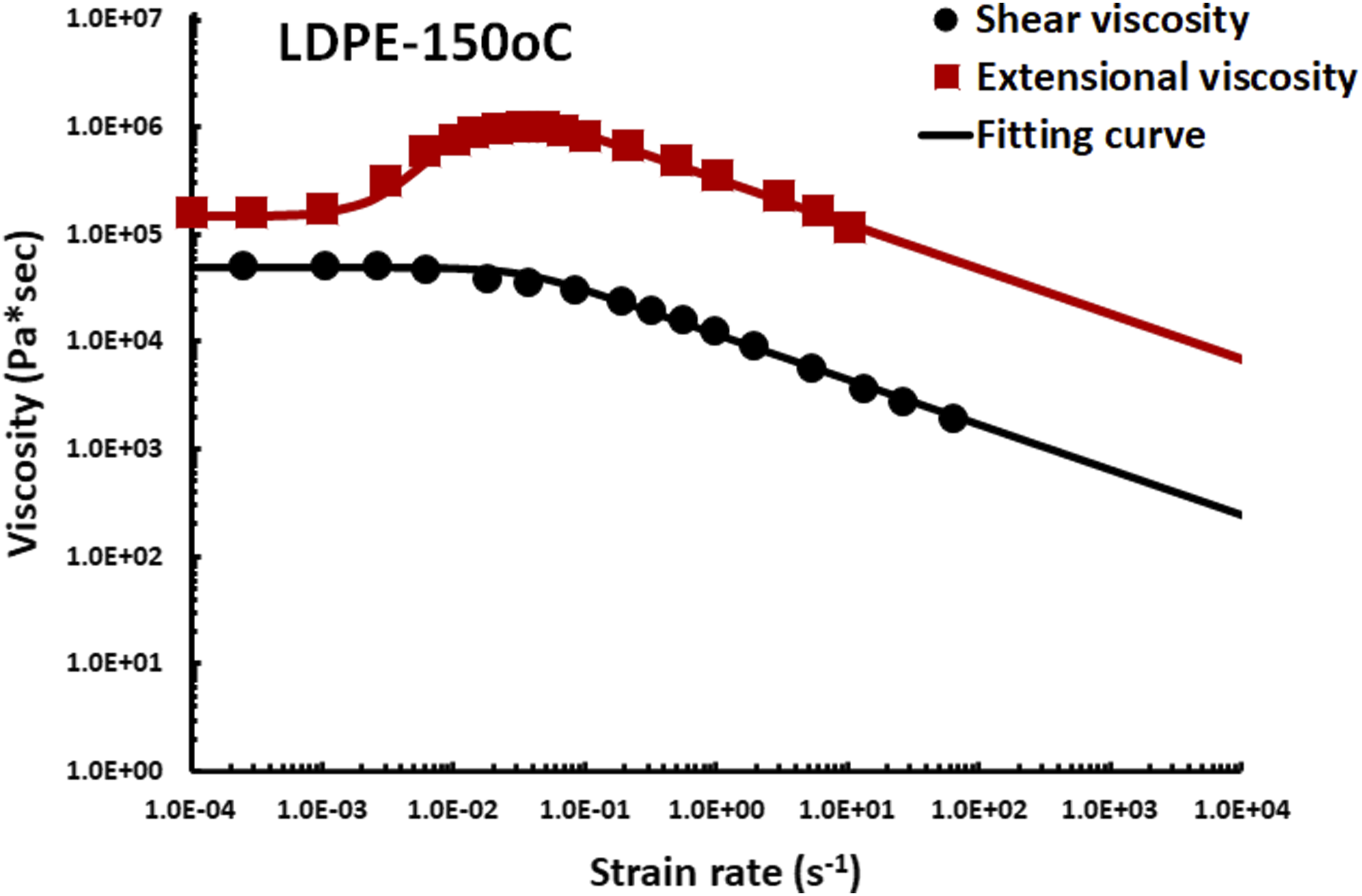
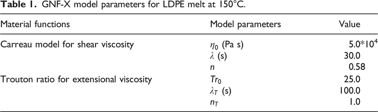
Figure 3 illustrates the dimensions and directions of a typical 4:1 planar contraction flow, wherein the contraction ratio is the ratio of the upstream height (HU) to the downstream height (HD); H
U
= 3.0 mm, HD = 0.75 mm. The total length is 60 mm, the upstream length is 30.0 mm, and the downstream length is 30.0 mm. The system width (W) is 40.0 mm. In the system Cartesian coordinates, the flow direction, flow gradient, and width directions are taken in the x-axis, y-axis, and z-axis, respectively. The contraction system was divided into 3D dense meshes of about 300,000 hexagonal elements in the Moldex3D. Because the dense hexagon is a high-quality element for the 3D numerical computation, no analysis of mesh sensitivity is performed. The fully developed flow of velocity profile is given in the inlet flow boundary condition. The apparent shear rate 3D geometry and hexagonal elements of 4:1 contraction flow.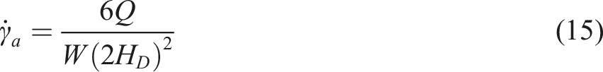
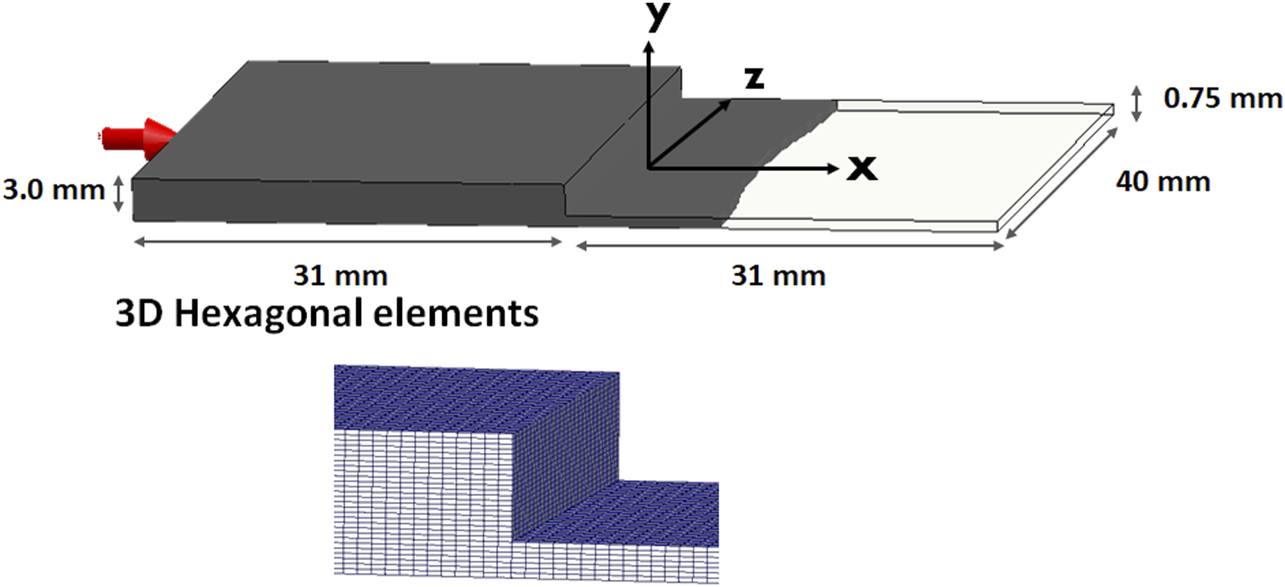
The apparent shear rates (SR), SR = 10 s−1 and 0.1 are given to find the flow rate of 37.0 and 0.37 mm3/s, respectively.
As a result, Figure 4 shows the flow front caught on the middle neutral (xz) plane inside the contraction flow at the fixed apparent shear rates of SR = 10 s−1 with respect to the weighted viscosity and extension fraction for the GNF shear viscosity. Such a flat front is a general continuous smooth shape in the absence of extensional viscosity. The shear viscosity of the fluid flowing in the upstream channel is high, and after passing through the contraction, the viscosity is decreased due to shear thinning. In addition, the shear viscosity is almost uniform in the upstream and downstream areas. At the end of the flow, the peculiar ear flow is prone to defects such as injection molding of entrapped air. Flow patterns of weighted viscosity and extension fraction for the GNF shear viscosity model in the 4:1 contraction flow simulation of LDPE melt at the isothermal temperature of 150°C and fixed apparent shear rate of 10 s−1.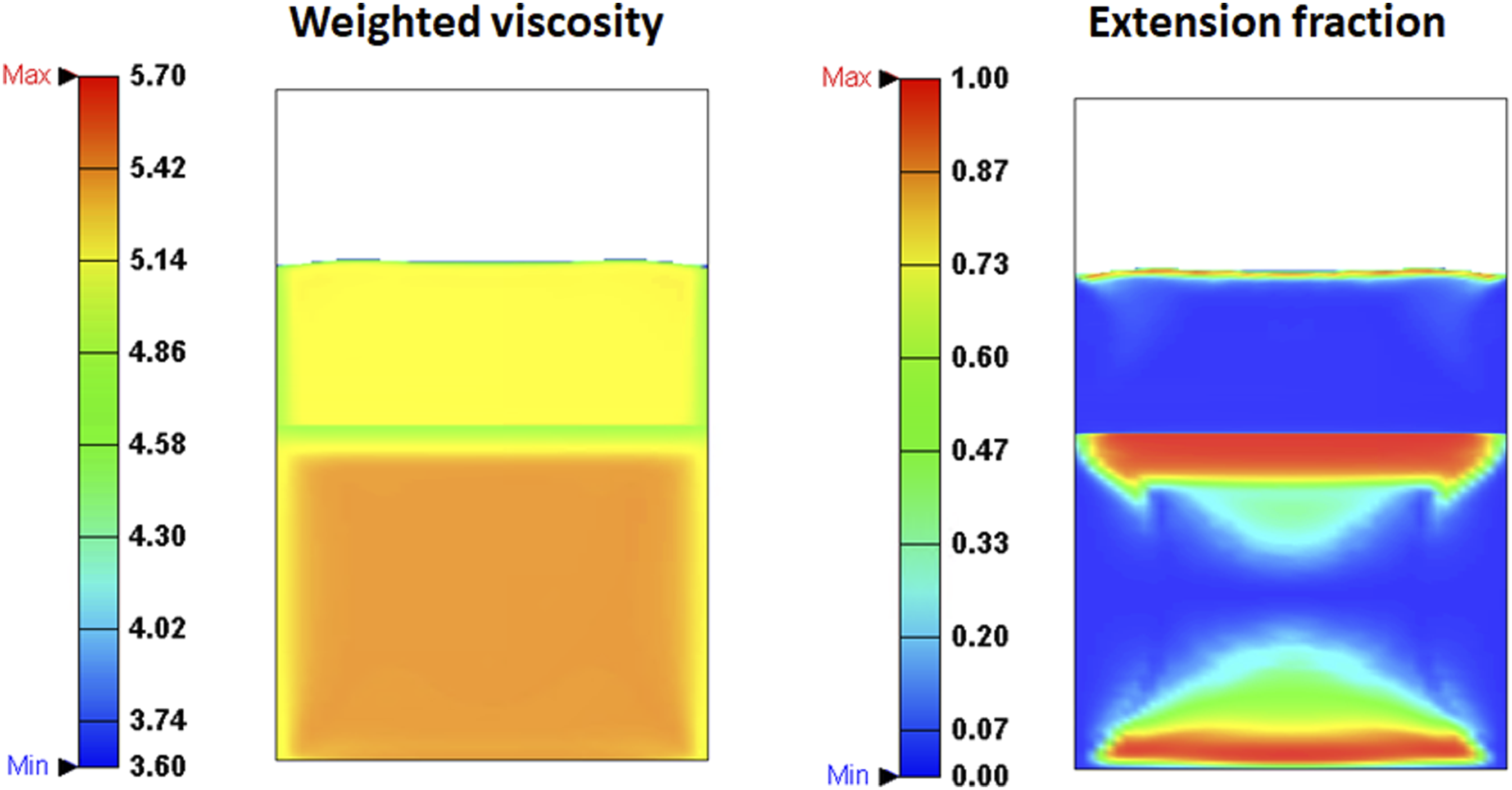
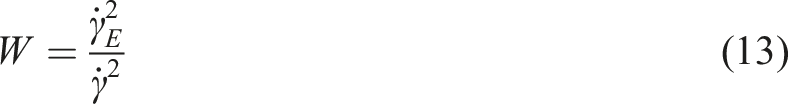
One can briefly introduce the calculation of the extension fraction of equation (13), which signifies the squared percentage of extensional rate. First, the rate-of-deformation tensor is rotated from Cartesian coordinates to streamline coordinates and then is decomposed as the characteristic shear and extensional tensors. Second, the characteristic shear and extensional rate are obtained. Finally, the extension fraction is calculated by equation (13). Details of the extension fraction are available elsewhere. 21 For the extension fraction distribution, the color bar implies the stronger the red extensional flow, the smaller the blue the shear flow, and the middle green, the mixed flow. Thus, the strong extension rates concentrate at the inlet, contraction, and flow front; elsewhere, the extensional rate is almost zero, indicating that the shear flow is dominant. This finding is in agreement with the general understanding of polymer rheology. 28
Figure 5 shows the flow front of GNF-X weighted viscosity in the presence of extensional viscosity. Obviously, the advance of the flow front in the center of the channel is slower than at the edges; it can be also considered as the preferential progression along the edges. This is the so-called extension-induced ear-flow front in the industrial practice of injection molding. Compared with GNF in Figure 4, GNF-X shows the higher weighted viscosity and the strong extension fraction in the downstream due to the contribution of the extensional viscosity. It seems that the patterns of weighted viscosity and extension fraction are very similar and related to each other. In the past, the ear-flow front simulation posed a difficult challenge for the rheological computation. From the simplified 2D flow simulations, there is no way to see the subtle differences in a complex flow. Only when the 3D fluid calculation considers the extensional viscosity can the ear-flow front be really simulated. The flow patterns of GNF and GNFX look very different. It is clear that the formation of ear-flow is related to high viscosity and strong extension. This result is consistent with the general understanding: flow behaviors depend on fluid viscosity and strain rates. Flow patterns of weighted viscosity and extension fraction for the GNF-X weighted viscosity model in the 4:1 contraction flow simulation of LDPE melt at the isothermal temperature of 150°C and fixed apparent shear rate of 10 s−1.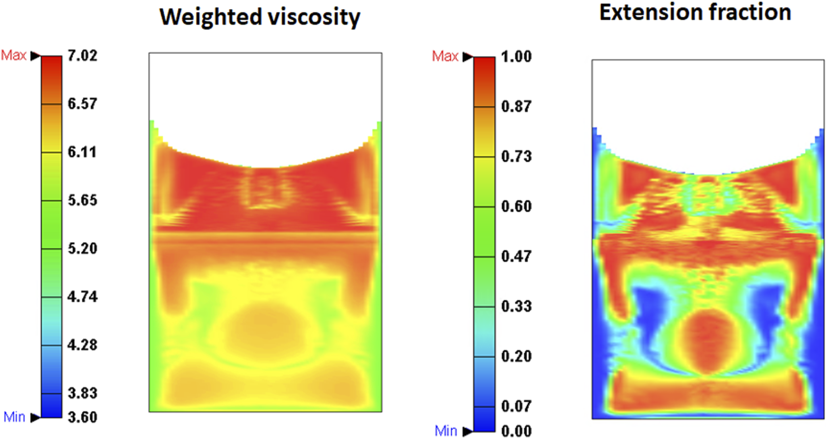
Furthermore, the ear-flow feature disappears at the slower apparent shear rate, SR = 0.1 s−1, as shown in Figure 6. The extension contribution dropped a lot. Basically, the studied fluid of long-branched LDPE melt is an anisotropic fluid with high Trouton ratio of max Tr = 28. In Figure 7, it is interesting to find no formation of ear-flow for the isotropic fluid with the fixed constant of Tr = 3 at SR = 10 s−1. Thus, one concludes that the ear-flow probably occurs in fast filling conditions for anisotropic fluids. Under the slower flow rate and lower Trouton ratio, the fluid approaches the GNF flow behavior. Flow patterns of weighted viscosity and extension fraction for the GNF-X weighted viscosity model in the 4:1 contraction flow simulation of LDPE melt at the isothermal temperature of 150°C and fixed apparent shear rate of 0.1 s−1. Flow patterns of weighted viscosity and extension fraction for the GNF-X weighted viscosity model with the isotropic Trouton ratio of Tr = 3 in the 4:1 contraction flow simulation of LDPE melt at the isothermal temperature of 150°C and fixed apparent shear rate of 10 s−1.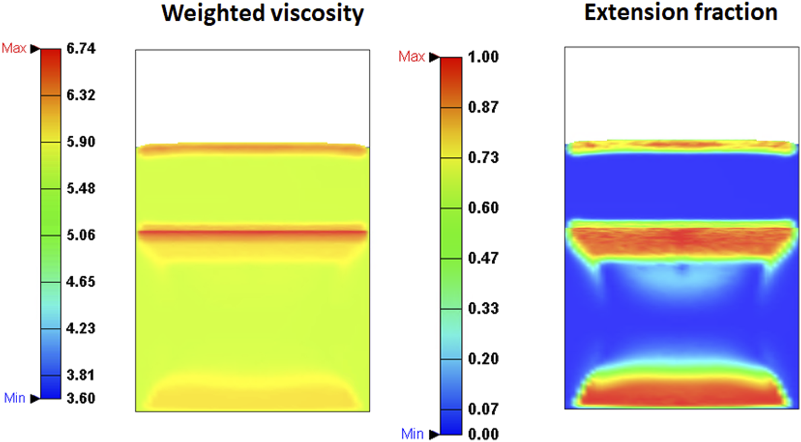
Injection molding flow of fiber-filled PP melt
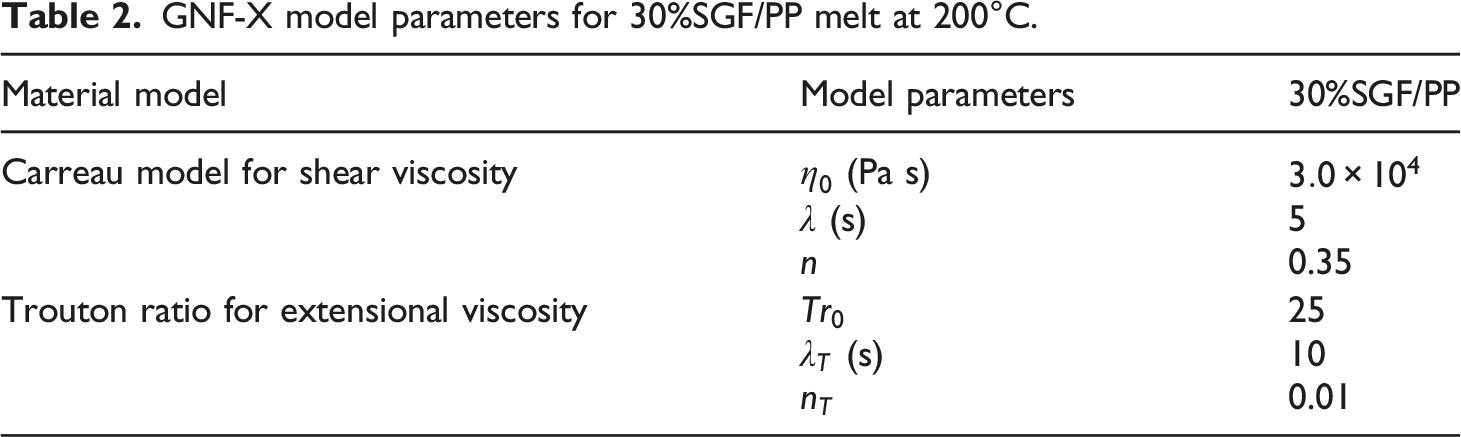
The ear-flow front is most often found in injection molding of fiber-filled polymer melts.1–3 Figure 8 shows that the shear and extensional viscosity of the 30 wt%SGF/PP (30 wt% short glass-fiber filled in polypropylene) composites at the fixed temperature of 200°C are higher than that of neat PP resin by two orders, wherein the related experimental data refer to the previous study of Mobuchon et al.
51
and the model parameters of fitting curves are addressed in Table 2. Thus, one can guess in advance that the anisotropic fluid of the fiber-filled PP melt should have the occurrence of ear-flow front. Shear viscosity and extensional viscosity against strain rates for 30 wt%SGF/PP melt at the fixed temperature of 200°C. GNF-X model parameters for 30%SGF/PP melt at 200°C.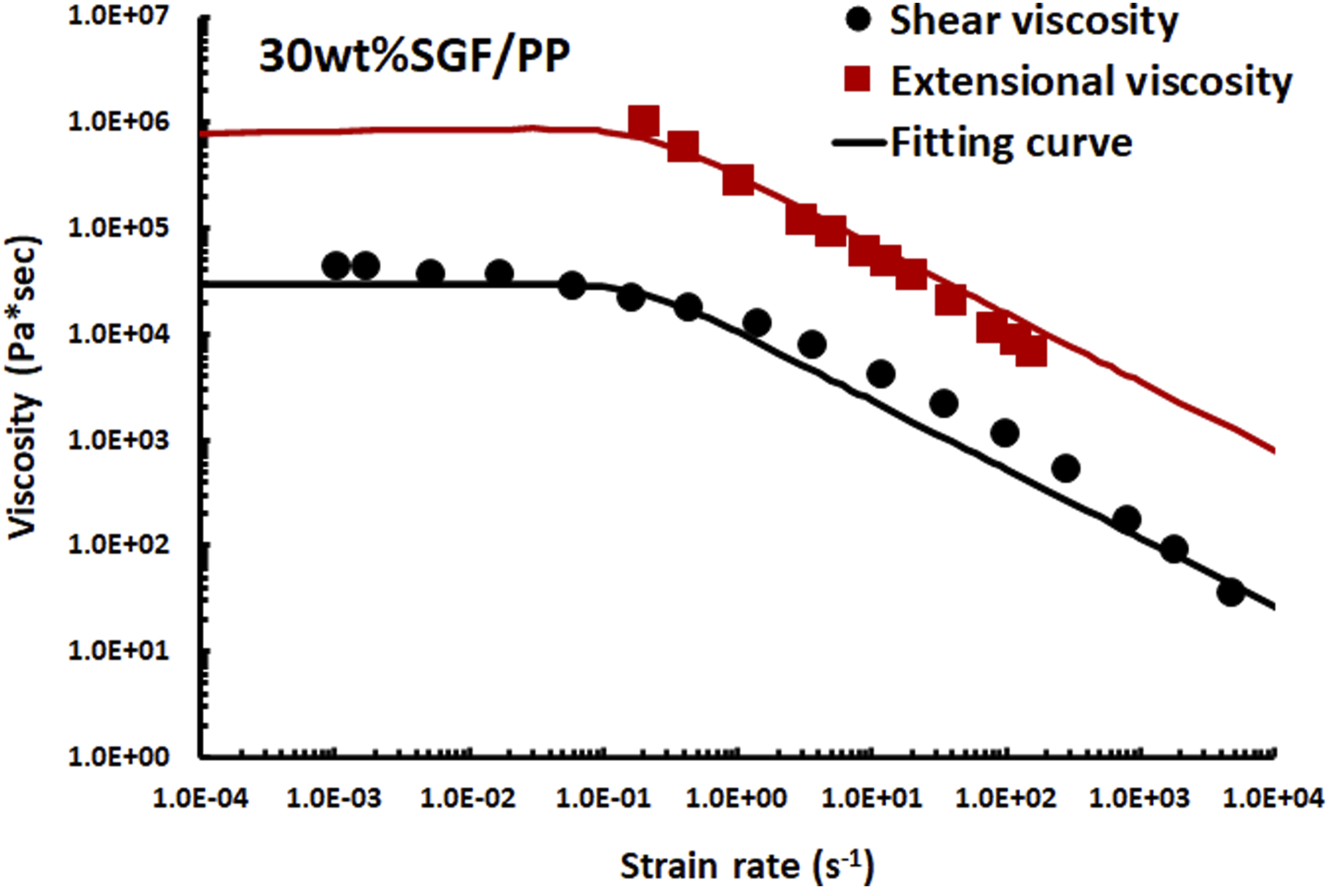
Based on the previous work of Tseng et al. 52 regarding the fiber orientation distribution for practical injection molded fiber composites, the geometry of the mold cavity was designed as a 150 ×150 ×3 mm3 plate by the material supplier BASF SE. 53 In the present study, the 3D filling flow simulations of injection molding for 30 wt%SGF/PP was performed through the Moldex3D. The molten plastic injected from the injector nozzle will go through a runner, and a gate and fill up in the cavity. The total volume of the cavity and runner was about 100 cm3. For the processing conditions, the filling time and filling rate were 1.8 s and 56 cm3/s, respectively. In addition, the mold and melting temperatures were set at isothermal temperature of 200°C. Details of material properties, molding conditions, and computation setups can be referred to elsewhere.52,53
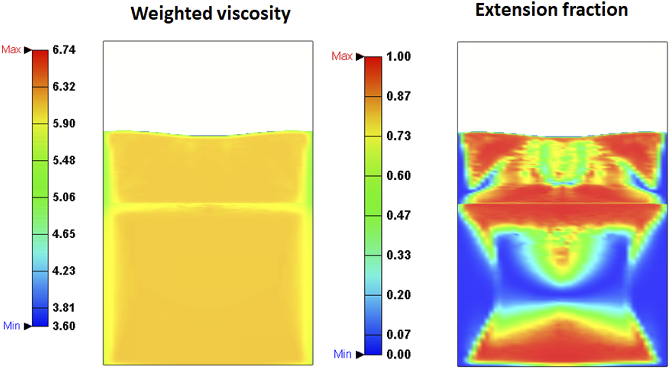
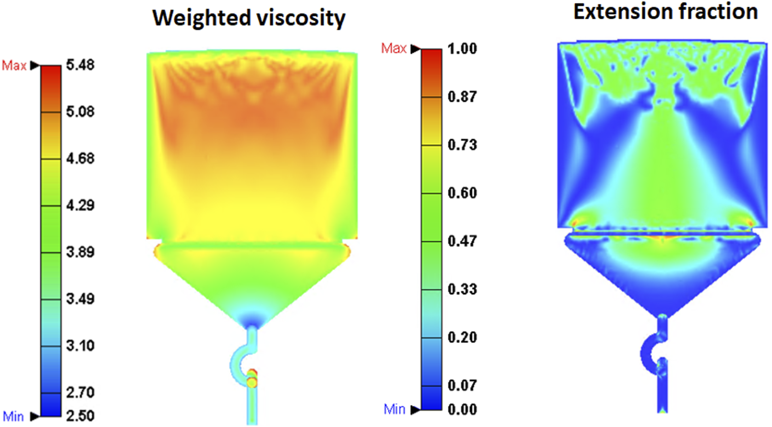
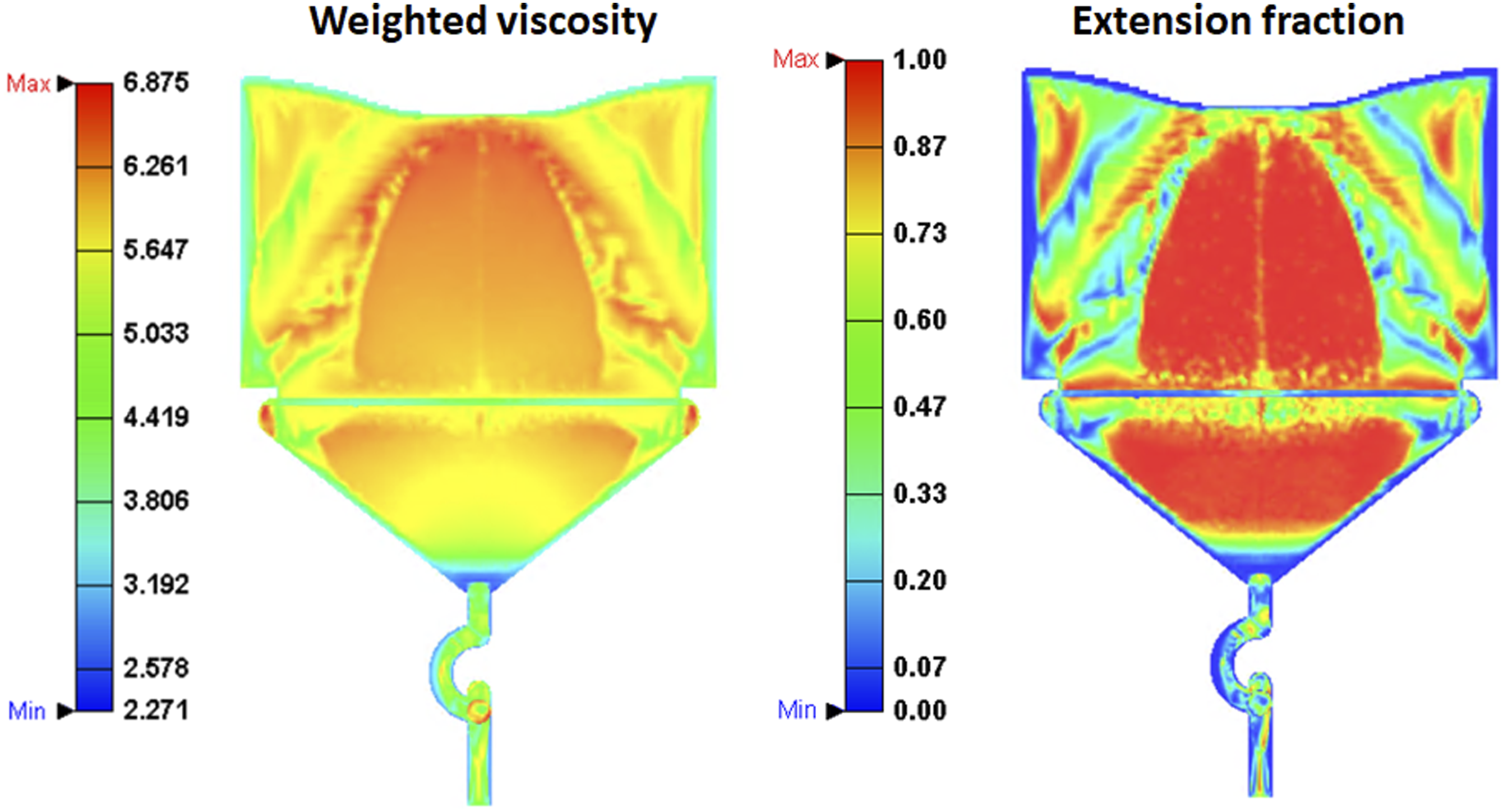
As a result, Figure 9 shows the flow patterns marked with white curves at different points in time for GNF and GNF-X. Expectedly, GNF-X has an obvious ear-flow front, while GNF does not. Figure 10 displays the fluid viscosity and extension fraction distributions for the GNF shear viscosity model, and for the GNF-X weighted shear/extensional viscosity model in Figure 11; these images of injection molding plate are similar to those of the planar contraction flow aforementioned in Figures 4 and 5. Therefore, the GNF-X weighted viscosity sufficiently demonstrated the ear-flow front in relation to extensional viscosity and extensional rate. Flow patterns of the GNF shear viscosity and GNF-X weighted viscosity models in the filling flow simulation of injection molding for 30 wt%SGF/PP melt at the isothermal temperature of 200°C. Flow patterns of weighted viscosity and extension fraction for the GNF shear viscosity model. Flow patterns of weighted viscosity and extension fraction for the GNF-X weighted viscosity model.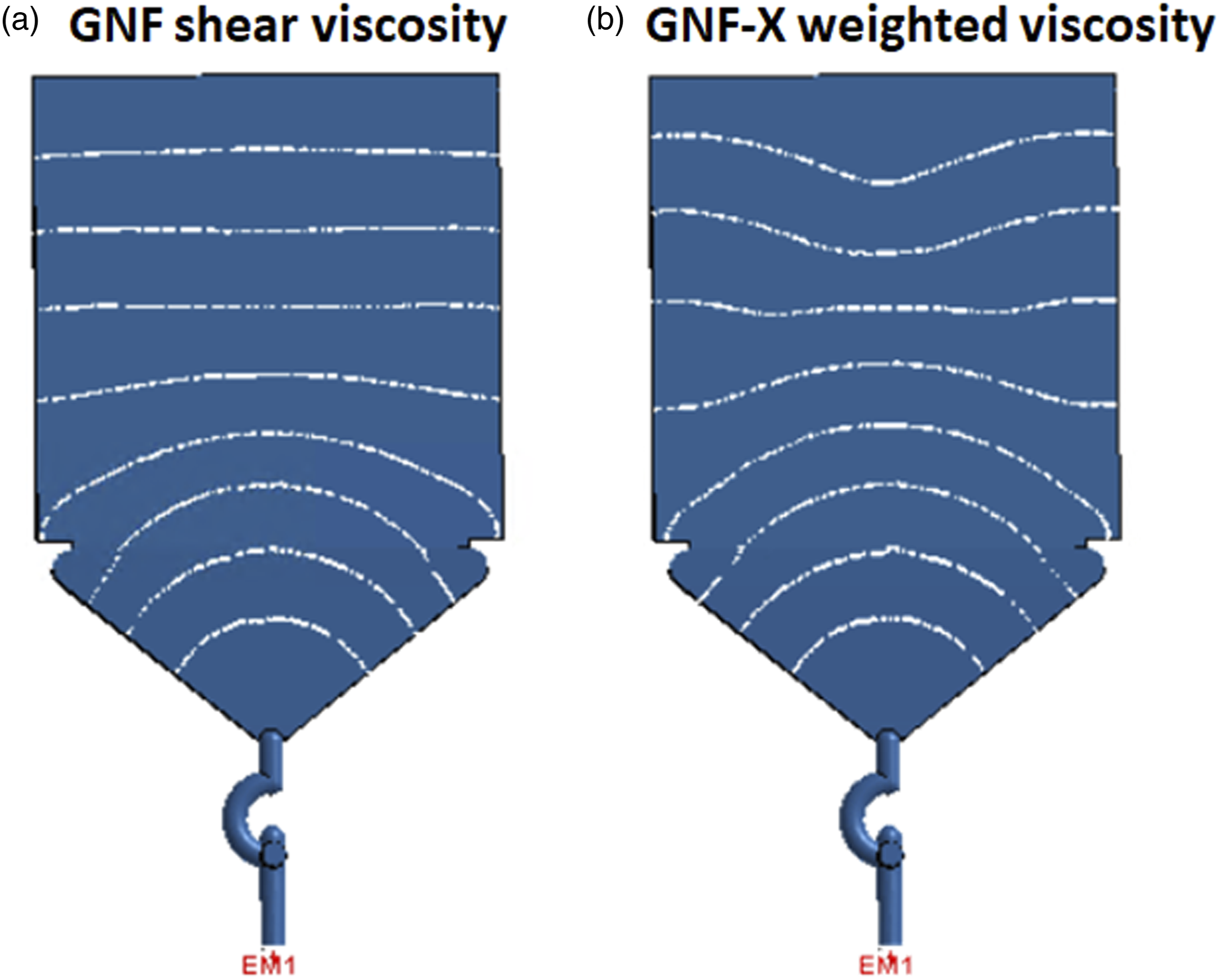
Previously, Favaloro, Tseng, and Pipes18,19 derived that the flow-fiber coupling model of informed isotropic (IISO) viscosity is a function of the rate-of-deformation tensor and fourth-order fiber orientation tensor. The use of the IISO flow-fiber coupling model is to simulate anisotropic flows in the compression molding of fiber composites, as well as the ear-flow front in injection molding. In particular to fiber-filled polymer melts, it appears that high fiber contents yield strong extensional viscosities; 14 thus, the effect of extension viscosity is attributed to the primary contribution of fiber orientation in the flow-fiber computation of IISO viscosity. Because of the contribution of extension viscosity, both GNF-X and IISO models, therefore, have the same capability in simulating the ear-flow front for injection molded fiber composites. The GNF-X can be widely used for neat polymer without fibers.
Conclusions
Through the state-of-the-art 3D flow simulations coupled with the objective GNF-X weighted shear/extensional viscosity model, it is a merit of research to demonstrate the effect of extensional viscosity on the formation of ear-flow front for injection molding in which the advance of the flow front in the center of the channel is obviously slower than at the edges. In addition, the extension-induced ear-flow front is related to the weighted viscosity and extension fraction. It is significant to point out that the ear-flow probably occurs in anisotropic fluids, such as long-branched neat polymers and fiber-filled polymer composites. In a practical case of injection molded fiber composites, the existence of ear-flow front is confirmed reliably. For the applicable potential of state-of-the-art predictive engineering tools, the GNF-X model is available in CAE (Computer-Aided Engineering) applications of polymer processing and fiber composite manufacture.
Footnotes
Declaration of conflicting interests
The author(s) declared no potential conflicts of interest with respect to the research, authorship, and/or publication of this article.
Funding
The author(s) received no financial support for the research, authorship, and/or publication of this article.