
Abstract
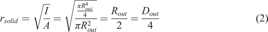
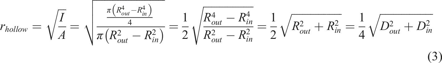
This paper describes both an experimental study and a numerical investigation on the compressive behavior of new types of solid as well as hollow composite columns, which consist of Unplasticized Polyvinyl Chloride (UPVC) tubes filled with expansive concrete. 32 specimens were categorized into four groups and cast with expansive concrete. Half of the specimens were confined additionally with two layers of GFRP wraps. Furthermore, two specimens were cast with ordinary concrete to be compared with those expansive counterparts. All the composite columns were tested under the monotonic compressive loading. The effects of GFRP confinement, aspect ratio of composite columns (L/D), and hollowness of concrete core on compressive behavior were investigated. It was demonstrated that adding expansive agents improved the load-carrying capacity and ductility of columns by enhancing the tri-axial state of stress in the concrete core. Moreover, an increase in aspect ratio decreased both peak load and its corresponding axial strain. Approximately 40% increase was observed in the values of peak load for specimens confined with GFRP wraps. Generally, concrete core removal in the hollow specimens resulted in slightly higher average compressive stress. Finally, a finite element (FE) simulation was performed using ABAQUS software, and the numerical results were validated with experimental tests of the present study.
Keywords
Introduction
Long-term durability achievement of reinforced concrete (RC) in coastal environments is a difficult task due to the combined dangerous effects of sodium chloride and magnesium sulfate existing in the seawater. 1 There are many cases of structural collapse reported from all over the world caused by the deterioration of the construction materials during their service lives. Rapid deterioration occurs in bridge sub-structures and piles, especially in those of harsh environments.2,3 Such damages have been reported in the forms of concrete cracking/spalling and steel corrosion in RC structures located in coastal regions, even in those constructed within the last 10 to 15 years ago. 1
Governments have been investigating in collaboration with private industries to develop optimized structural systems 4 and as an example, proposed the concrete-filled steel tube (CFST). In CSFT columns, the tube confines the concrete core leading to higher ultimate strength and strain. In turn, the tube inward buckling is delayed because of the concrete core. However, corrosion of the steel is a shortcoming preventing designers from using this tubing material. It is estimated that only in the US, over US$1 billion is spent annually for the repair and replacement of waterfront piling systems. 5
FRP possesses some advantages in comparison with steel, namely a higher strength over weight ratio and especially more chemical resistance to corrosive environments. The use of FRP composites has grown rapidly in the past two decades. As an important endeavor, FRP wraps are utilized for retrofitting structures in different forms such as jackets, sockets, spirals, etc. leading to strength and durability enhancement.5–10 Howbeit relatively low rupture strain of FRP sheets imposes an abrupt failure on FRP-confined structures especially to those under compression.
An alternative to the advanced composite tubing materials is the commercially available Unplasticized Polyvinyl Chloride (UPVC) pipe.1,2,6 UPVC pipes can also be used as a stay-in-place formwork, are convenient to be assembled, highly resistant to corrosion, and cheaper in comparison with steel tubes and FRP composites. 1 They also benefit from high strength over weight ratio, service life of 50 years, and elastic behavior under large deformations. 2 Furthermore, heat conductivity of UPVC is about %0.45 of that of steel, which makes a suitable condition for concrete curing. 11
Shrinkage of concrete is a phenomenon that affects concrete durability and causes serious damages to concrete structures. 12 It also reduces the bond between the concrete core and the tube.13,14 Quite a few of studies revealed that expansive additives reduce the shrinkage of concrete by inducing chemical reactions in the mixture.15,16 Expansive concrete is categorized into two groups of shrinkage compensating and pre-stressed concrete. The main difference between these two types is the magnitude of concrete expansion through chemical reactions. 12 In the latter one, the expansion is high enough so that not only it can compensate for the shrinkage, but it also imposes residual stress on the pipe reacting against the dilation of the concrete core.
Many studies have been conducted on the performance of steel and FRP tubes as the confinement for concrete. However, vulnerability of steel materials in the harsh environment and low ductility of FRP materials lead to the choice of material having both suitable durability and ductility. In this research, UPVC is chosen over steel and FRP tubes because of the aforementioned reasons. Cost efficiency, recyclability, and durability are the most desirable features taken into account by the authors. Acting as an integrable mold capable of forming composite action, high chemical resistance, and a long service life make the proposed system suitable for cast-in-place piles and bridge piers especially those in coastal regions. Based on authors’ knowledge, there are very limited studies on the compressive behavior of concrete-filled UPVC tubes. In contrast with the number of research dealing with only ordinary concrete, test samples with expansive concrete were cast and analyzed to present a comprehensive investigation. In this research, expansive materials were added to the concrete mixture for two reasons. First, to prevent concrete from shrinking, which results in a separation between the concrete core and the UPVC pipe. Second, to create pre-tension in the pipe by the means of concrete expansion providing concrete better confinement especially at the beginning stages of loading. Since there is no numerical analysis reported in literature dealing with concrete and UPVC interaction, a model for confined expansive concrete using ABAQUS was proposed to predict the performance of such columns.
Experimental program
Specimens
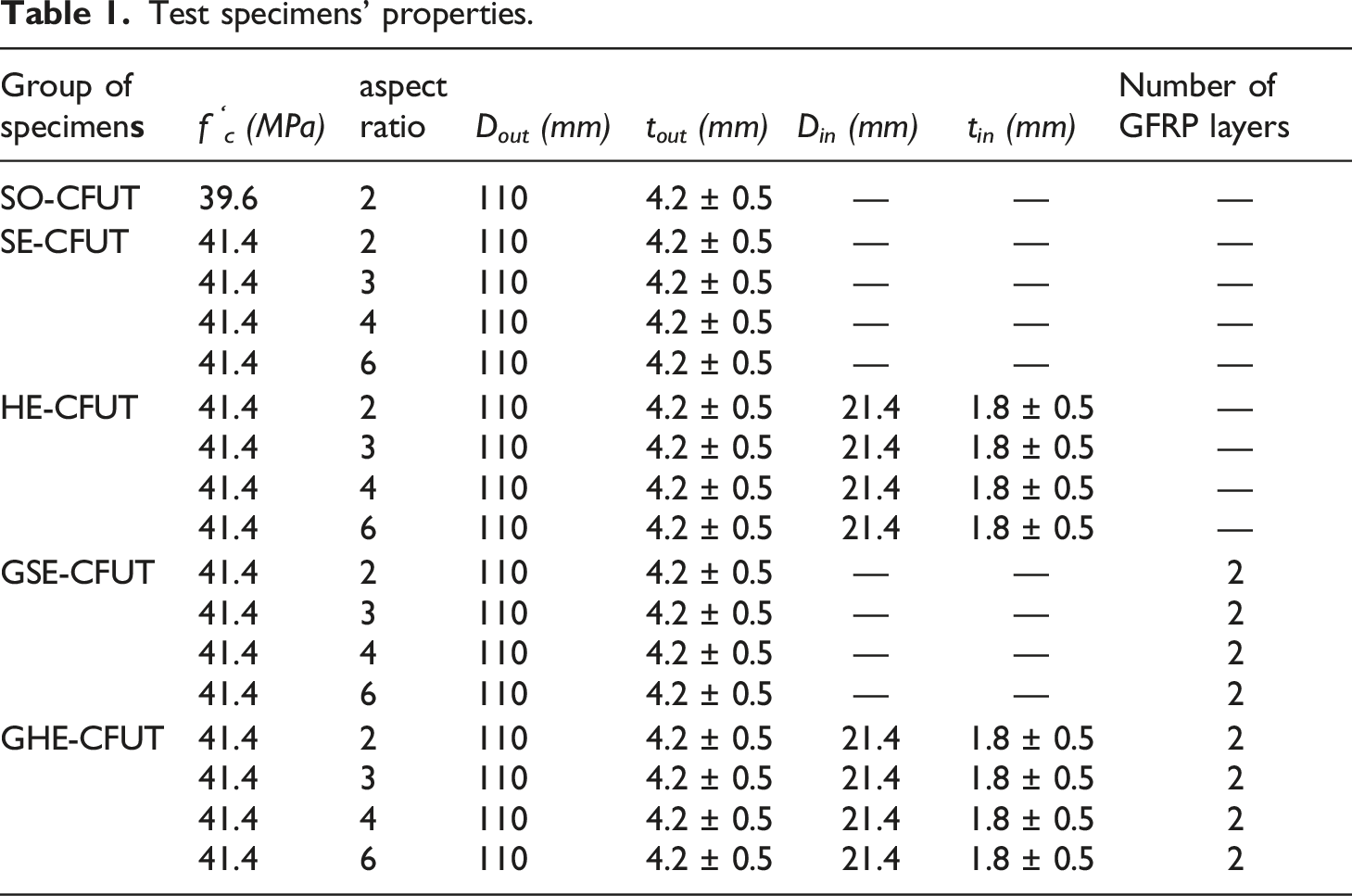
Test specimens’ properties.
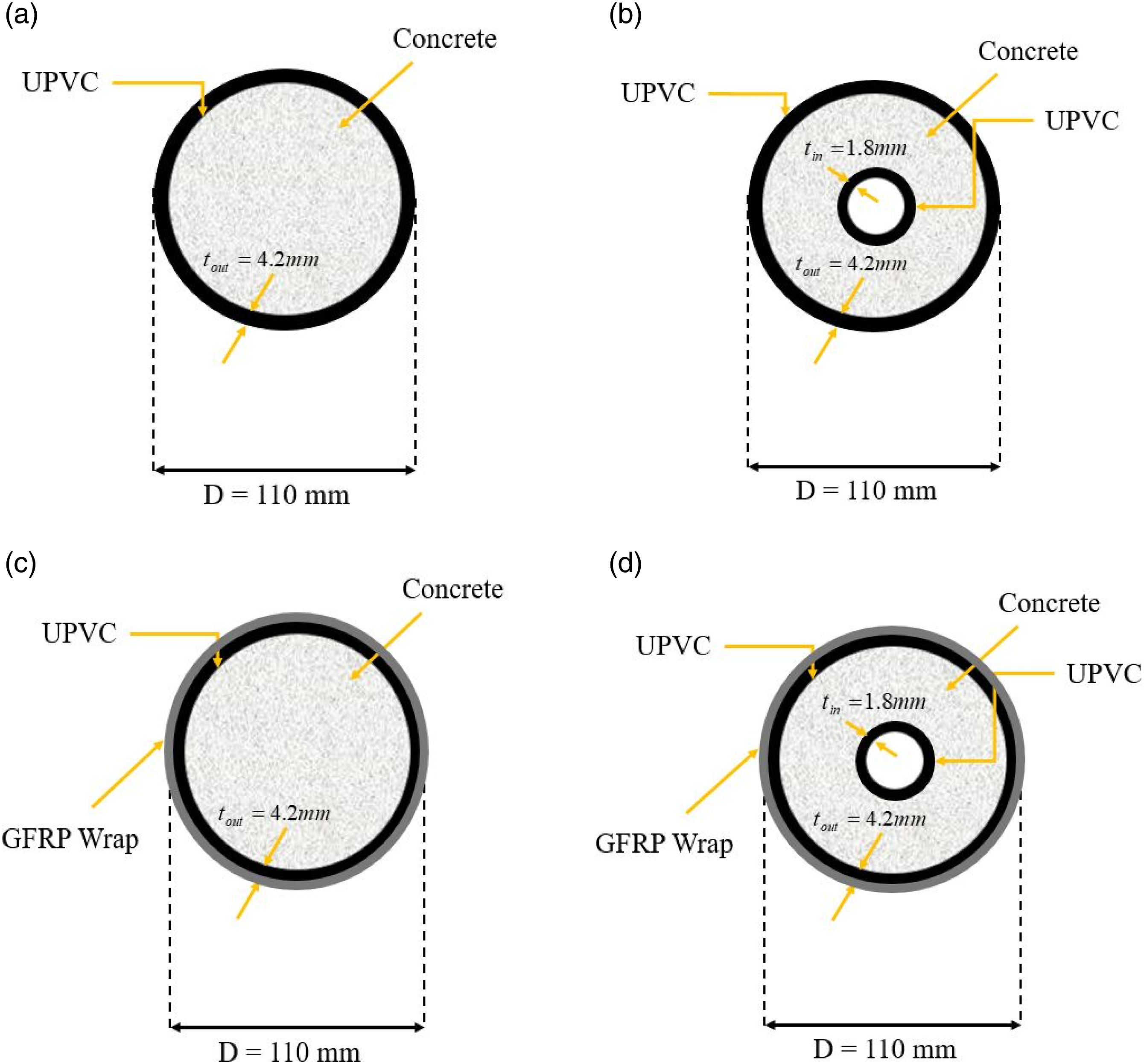
Geometric cross-sectional view of confined concrete columns: (a) SE-CFUT; (b) HE-CFUT; (c) GSE-CFUT; (d) GHE-CFUT.
Specimen preparation
All the specimens were cast and cured in the Concrete Technology Research Laboratory at the Sharif University of Technology. For each specimen, a UPVC pipe was cut to desired lengths. Two types of glue were utilized to affix UPVC pipes at one end to a wooden plateau to assure its integrity, deformability, and internal impermeability, as shown in Figure 2(a). The UPVC pipe acted as a stay-in-place mold during casting and a part of the composite column during the loading phase. (a) Ground faces of test specimens; (b) Specimens with sulfur cap.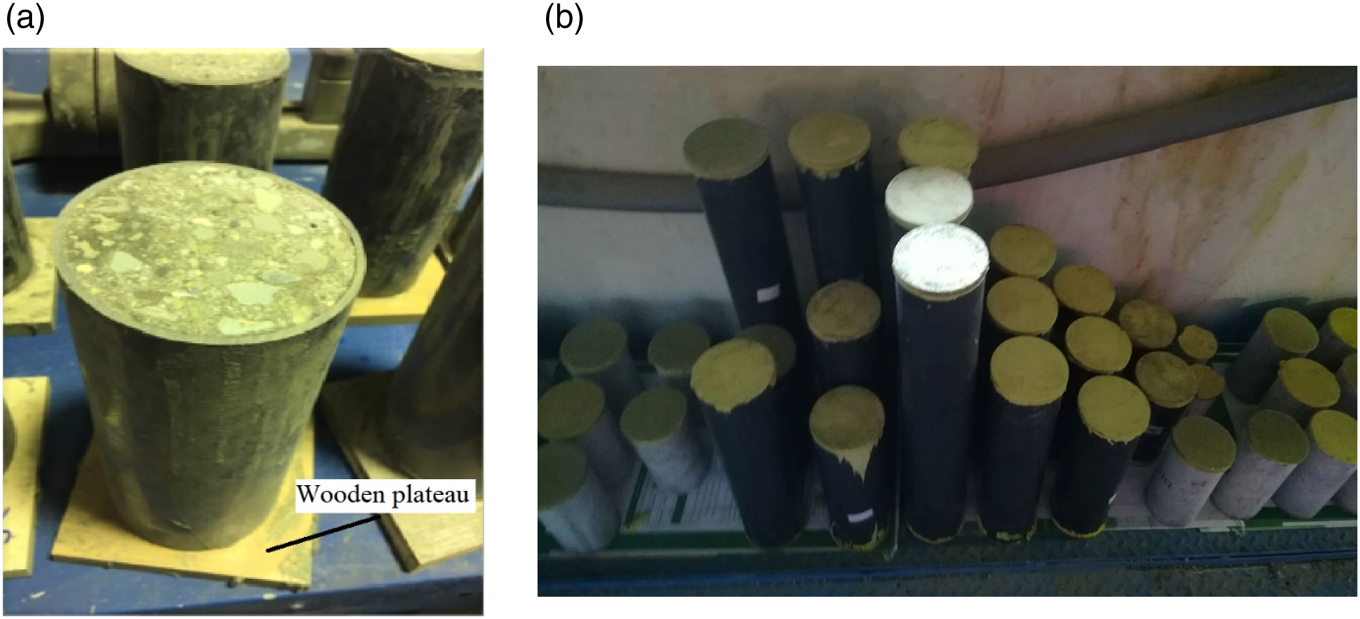
All the specimens were casted and left under wet burlap for a day, then cured in a water tank for 28 days. Among the specimens, 16 were selected to be wrapped with GFRP laminates. Two layers of the GFRP wrap were applied using a manual wet layup process to create GFRP-confined expansive CFUT specimens. All the test and control specimens were ground with a grinding machine at top, then capped with molten sulfur at both ends to remove the surface imperfections and avoid undesired stress concentration as depicted in Figure 2(b).
Material properties
Concrete
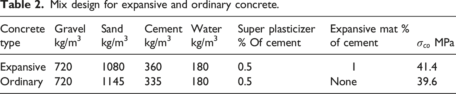
Mix design for expansive and ordinary concrete.
UPVC pipe
Commercially available Unplasticized Polyvinyl Chloride (UPVC) is a common super elastic material used in piping as well as doors and windows, which is advantageous in terms of high durability, less maintenance cost, and energy efficiency.
Different classes of pipes are usually categorized based on the nominal pressure number (PN) in bar units, which they can handle. In this study, PN is extensively used to refer to the strength grade of UPVC tubes. UPVC tubes used for water supply with the nominal internal pressure resistance of 10 bars were utilized for all the column specimens. These pipes tubes had an outer diameter of 110 and an average thickness of 4.2 mm. UPVC tubes conforming to ISO9001 were procured from Vinoplastic plastic pipe manufacturing company.
To determine the tensile strength and other physical properties of the plastic pipe, four tensile coupons, as shown in Figure 3(a), were prepared according to ASTM D638 and tested similar to the procedure illustrated in Figure 3(b). The tensile stress-strain curve of the UPVC plastic pipes obtained from the laboratory tests is shown in Figure 3(c). (a) Tensile coupon specimens; (b) Test setup of coupon specimens; (c) Tensile stress-strain curve of the UPVC pipe.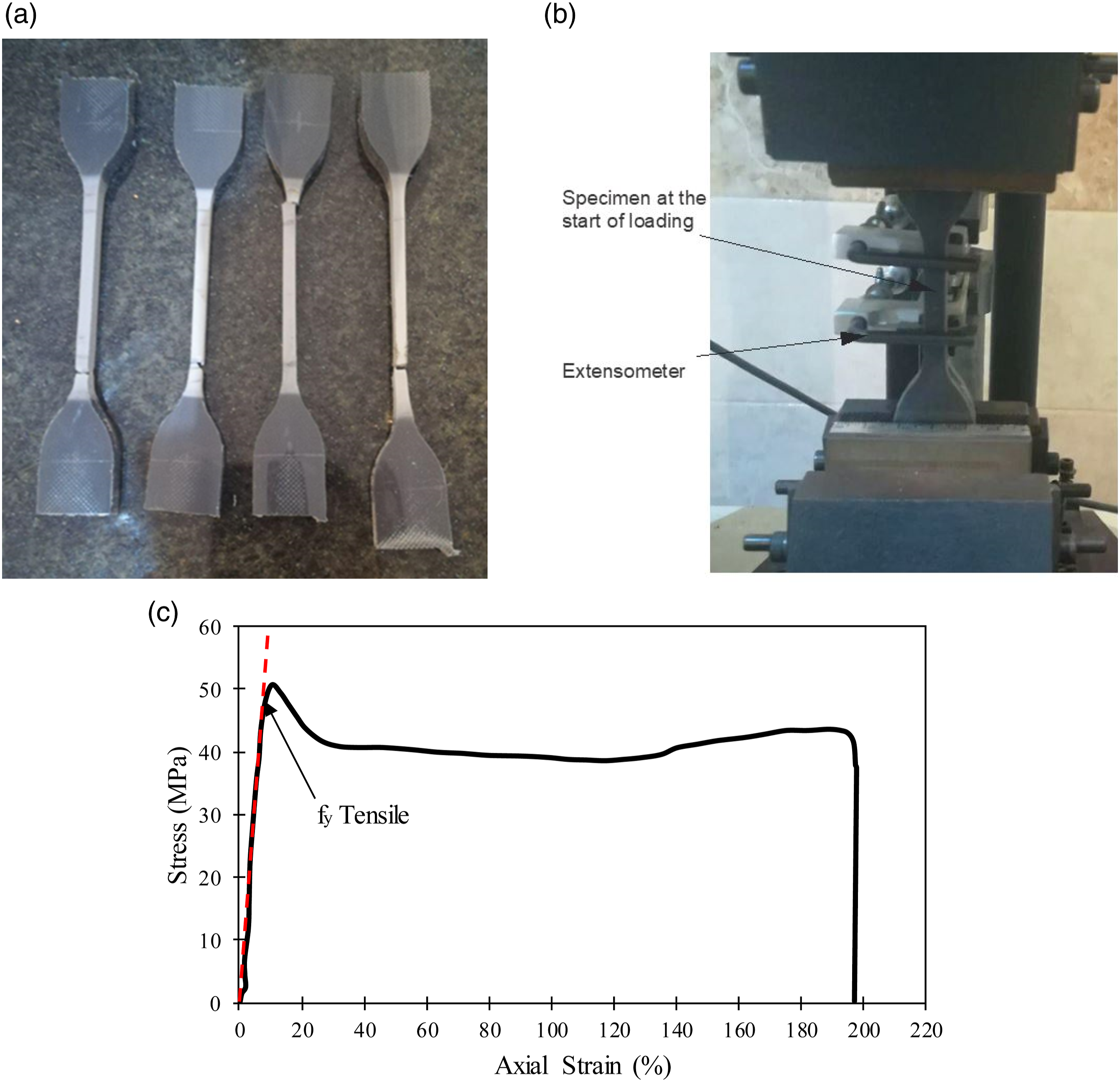
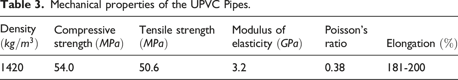
Mechanical properties of the UPVC Pipes.
(a) Compressive stress-strain diagram of UPVC pipe; (b) Deformed shape of UPVC pipe under compression.
GFRP wrap
Bidirectional GFRP wraps were used to confine solid and hollow expansive CFUT specimens. GFRP wraps included E-glass fiber and polyester resin as the matrix with weight percent of 30 and 70, respectively. Each wrap with a thickness of 0.17 mm was made from long fibers oriented within 90 degrees from each other. These wraps were attached to the UPVC tubes through the manual wet lay-up method by wrapping GFRPs impregnated with epoxy-resin adhesive with an overlap length of 100 mm.
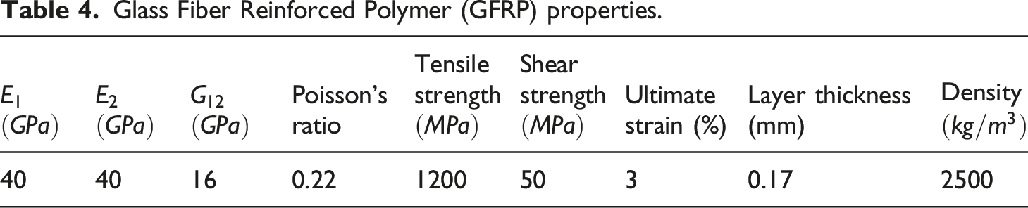
Glass Fiber Reinforced Polymer (GFRP) properties.
Test procedure
The specimens were tested under the action of displacement-control monotonic loading using a servo-hydraulic Universal Testing Machine (UTM) with a load capacity of 1000 kN. The loading process was performed at a rate of 0.5 mm per minute. The testing apparatus and specimen setup are shown in Figure 5. It is important to be mentioned that the sulfur capping process was carried out accurately at the top surface of specimens to yield a thin and even layer. In order to maximize the precision of test results, two longitudinal Linear Variable Differential Transformers (LVDT) were placed on two opposite sides of the specimens as shown in Figure 5. The displacement data for all specimens was recorded up to a strain of about 2% at regular intervals. Compressive test on CFUTs.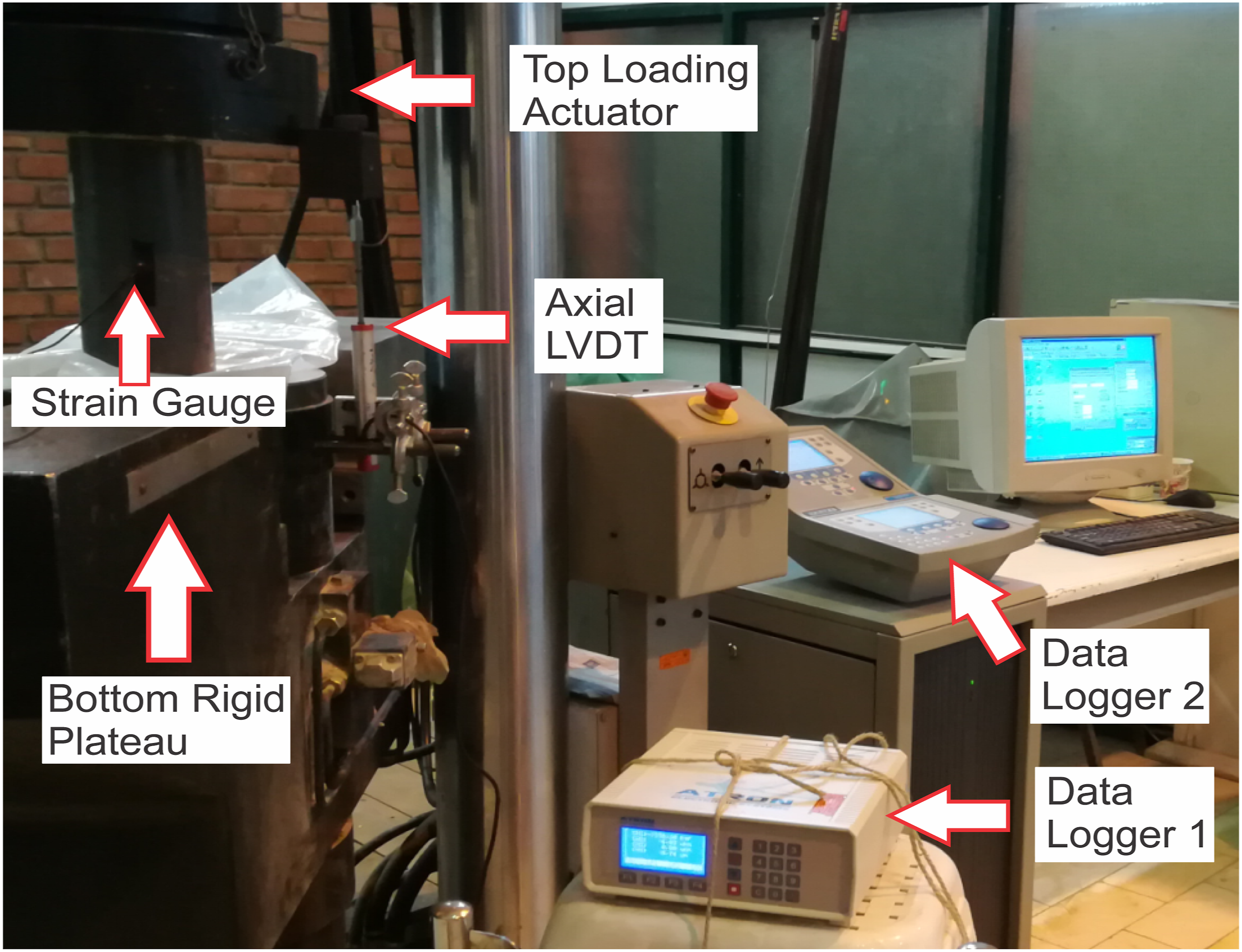
Test results and discussion
Benefits of expansive concrete
In order to evaluate the effect of the expansive agent on the performance of composite columns, solid expansive CFUTs and those counterparts cast with ordinary concrete were tested and compared. Figure 6 shows the different compressive behavior of SE-CFUT2 in comparison with SO-CFUT2 columns. One of the major shortcomings of concrete-filled steel/plastic tube columns, as described, is related to the difference between the Poisson’s ratio of the concrete (about 0.2) and the confining medium (about 0.3 for steel and 0.38 for UPVC). This may lead to a reduction in the confinement, and hence, a decrease in load-carrying potential of the proposed systems due to the larger lateral expansion of the pipe. A proper dosage of the expansive agent can create pre-tension in the pipe and result in a better tri-axial state of stress in the concrete core provided the longitudinal expansion of concrete is prevented. In this research, a dosage of 1% of expansive additive improved peak load considerably by 15%. Moreover, the post-peak descending slope of SE-CFUTs was less steep in comparison with SO-CFUTs, which is a consequence of the more ductile behavior of the expansive CFUT columns. The Ductility Index (DI) is defined as Expansive CFUT V.S. ordinary CFUT specimen in compression.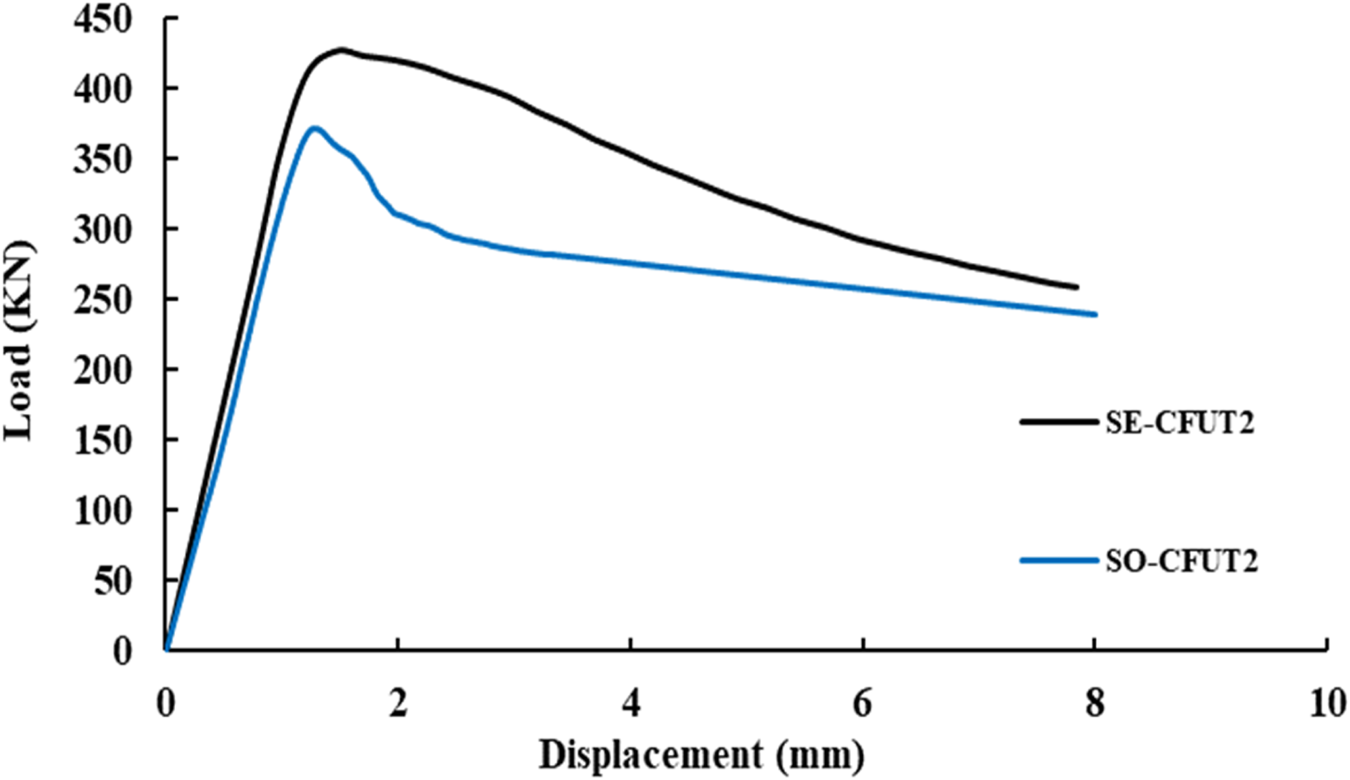
Mode of failure
All the specimens in each group behaved more or less in the same manner during the loading process. Generally, due to the UPVC mechanical properties, a very ductile behavior with gradual post-peak loss of strength was observed for the CFUT specimens in which no cracking or pipe rupture was observed and the core concrete kept dilating and pushing the pipe outward. The failure pattern of the UPVC-confined specimens can be categorized into two types, namely drum-shaped and diagonal bulging as shown in Figure 7(a) and (b). The most important characteristic of the former one is concrete crushing due to shear stresses in a direction in which the confinement effect is less. This mode of failure was also observed by Wang and Yang.
19
Color change was observed in UPVC tubes, which is attributed to the UPVC stretching. As the tube thickness imperfection reduced the drum-shaped bulging was more inclined to occur. Drum-shaped bulging is the result of a compressive failure of the concrete core. These bulges were observed to occur either near the ends or mid-height of the specimens, however, as a general trend, the bulges were more inclined to form at the bottom of the test samples as the aspect ratio increased. On the other hand, the GFRP-confined CFUTs experienced a relatively sudden loss of strength due to GFRP rupture, and subsequently, a brittle fracture near the mid-height or ends of tubes occurred. However, due to the presence of the UPVC pipe, the observed behavior was more ductile in comparison with concrete specimens confined only with GFRP wraps.
5
These modes of failure are depicted in Figure 7(c) and (d). In higher aspect ratios, the failure in GFRP was local and near the ends rather than a complete rupture as occurred in specimens with lower aspect ratios. UPVC pipes were cut completely after testing in order to investigate the concrete core. It was seen that the concrete core was totally crushed and there was no bond formed between the core and the confining medium. It is worth mentioning that a sudden load drop associated with premature failure was observed in two test specimens, one of which was related to the premature failure in GFRP epoxy-resin adhesive. The other one was the pipe’s rupture which was related to a weak spot in the pipe’s wall with lower thickness due to the undesired imperfections. Different aspects of failure mode: (a) Drum shaped bulges; (b) Diagonal shear failure; (c) Complete longitudinal GFRP rupture; (d) Local longitudinal GFRP rupture near the end of the specimen; (e) Crack patterns in concrete cross-section.
Load-deformation characteristics
The load-displacement curves of all groups of specimens tested in this study are shown in Figure 8. A reduction in the initial stiffness and peak load, and an increase in displacement corresponding to the peak load were observed with an increase in the height of columns. However, such an increase in the displacement corresponding to peak load is not representative of a better structural behavior under compression. Avoiding misinterpretations, normalized curves are also proposed. Load-Deformation curves of: (a) Solid expansive CFUTs; (b) Hollow expansive CFUTs; (c) Solid GFRP confined expansive CFUTs; (d) Hollow GFRP confined expansive CFUTs.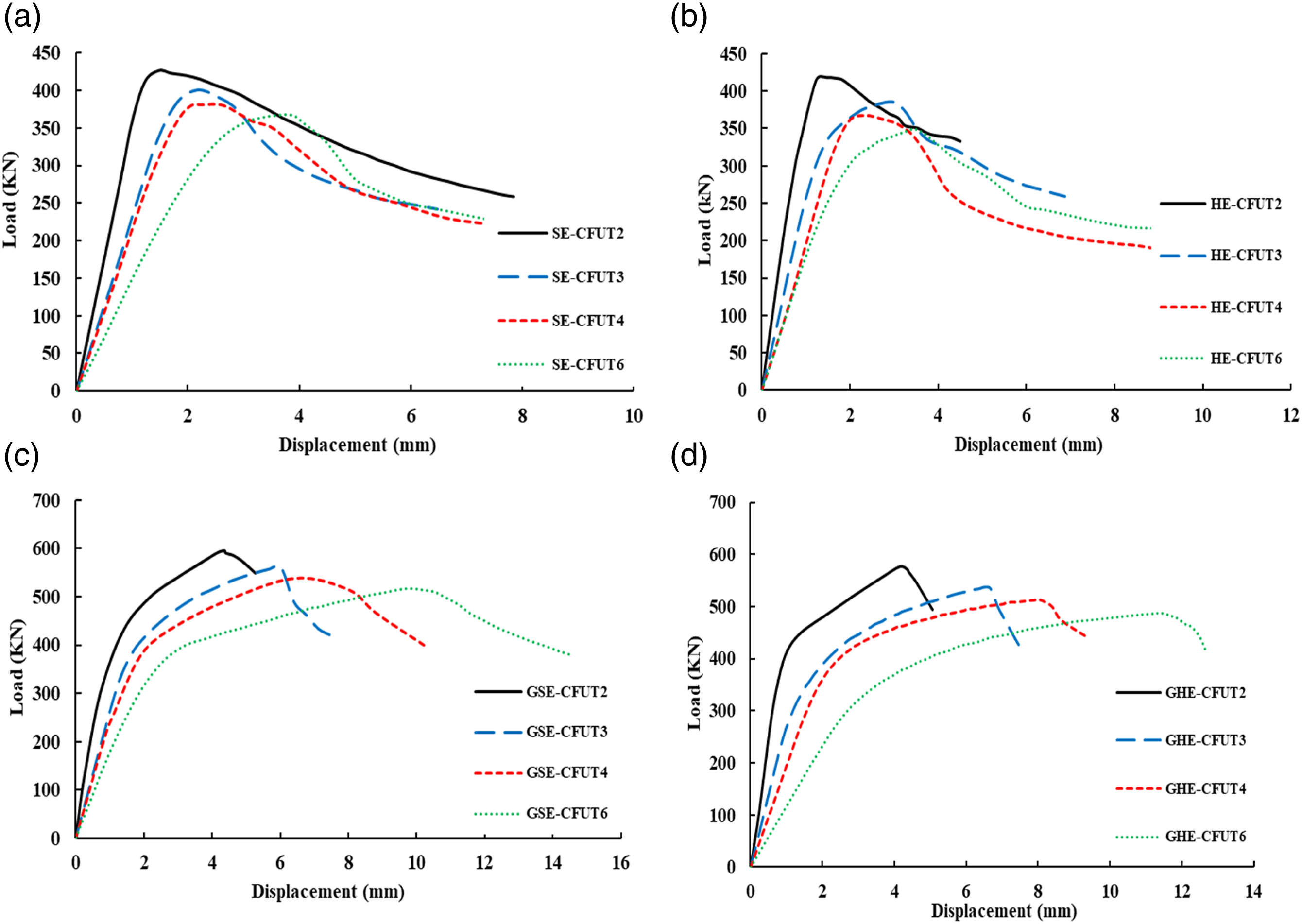
In order to address the effect of GFRP wraps on the behavior of CFUT columns, the behaviors of SE-CFUT3 and GSE-CFUT3 columns under the monotonic compressive load are illustrated in Figure 9. As shown in this figure, the load-strain curves of CFUT columns consist of 3 phases. The first one is the ascending branch at the beginning of the loading to the peak load (point A). The second one is the descending post-peak phase which can be identified with a notable load drop (from point A to B). The last one can be recognized with a relatively residual plateau (between points B and C). On the other hand, one can assimilate the behavior of GFRP-confined CFUTs with a bi-linear diagram followed by a relatively steep curve. Both lines are ascending, however, the second one is noticeably less steep than the first one. In these specimens, a sudden fracture was observed shortly after GFRP wraps got ruptured (point Comparison between the CFUTs and GFRP-confined CFUTs.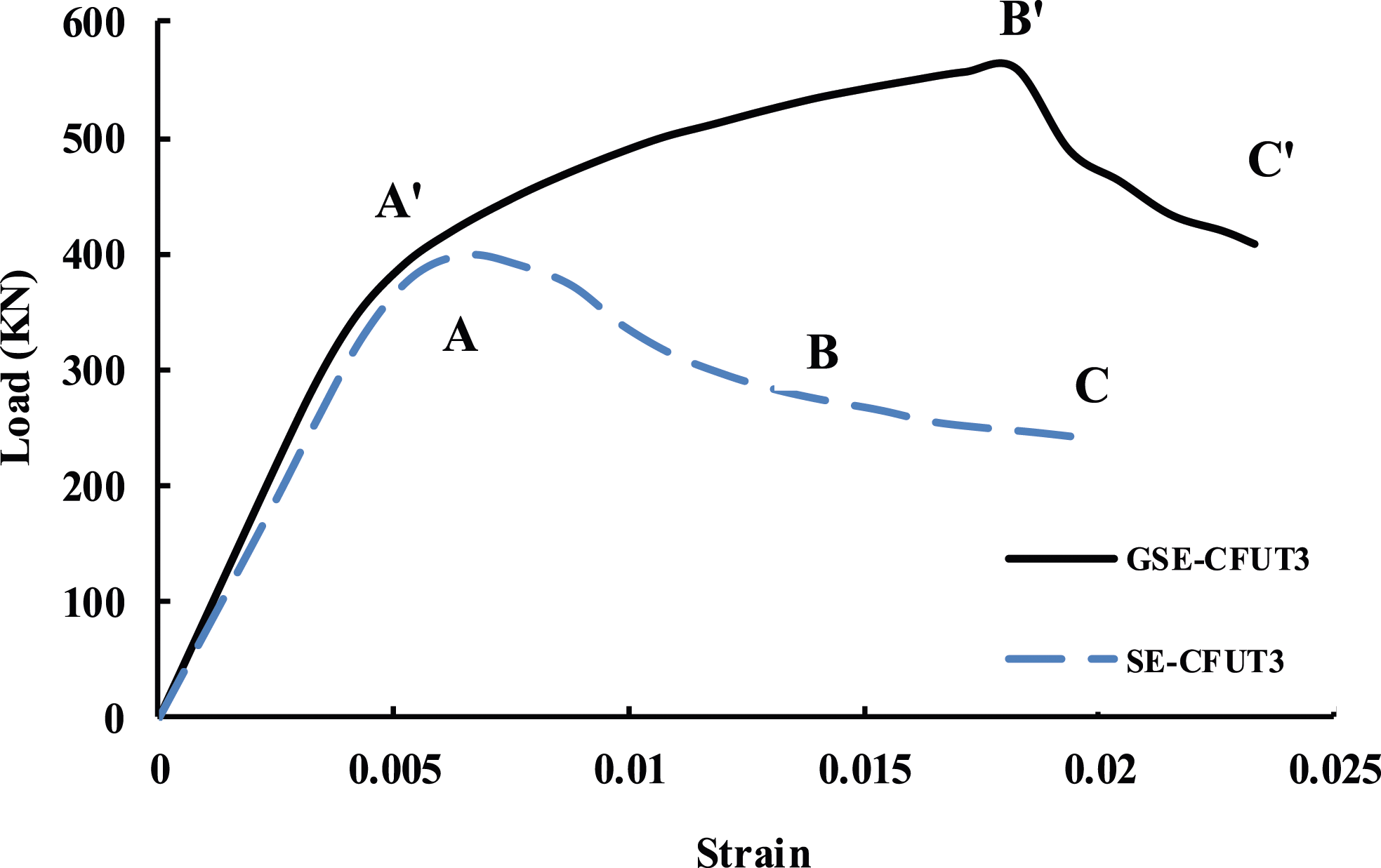


Test results.
The influence of aspect ratio on the behavior of specimens is depicted in Figure 10. In both diagrams, characteristics such as the concrete strength, pipe thickness, etc. are constant while the aspect ratio varies. It is shown that as the height of the concrete columns increases, the peak load and generally its corresponding strain decrease in the range of 6 to 17 and 5 to 25%, respectively. An increase in aspect ratio makes the descending branch steeper and reduces the ductility values, while the ascending branch was not considerably influenced by the variation of aspect ratio. This reduction in the values of ductility comes from the fact that the confinement capacity of the pipe decreases with an increase in the specimens’ height. Aspect ratio effect on the behavior of specimens in (a) CFUTs; (b) GFRP confined CFUTs.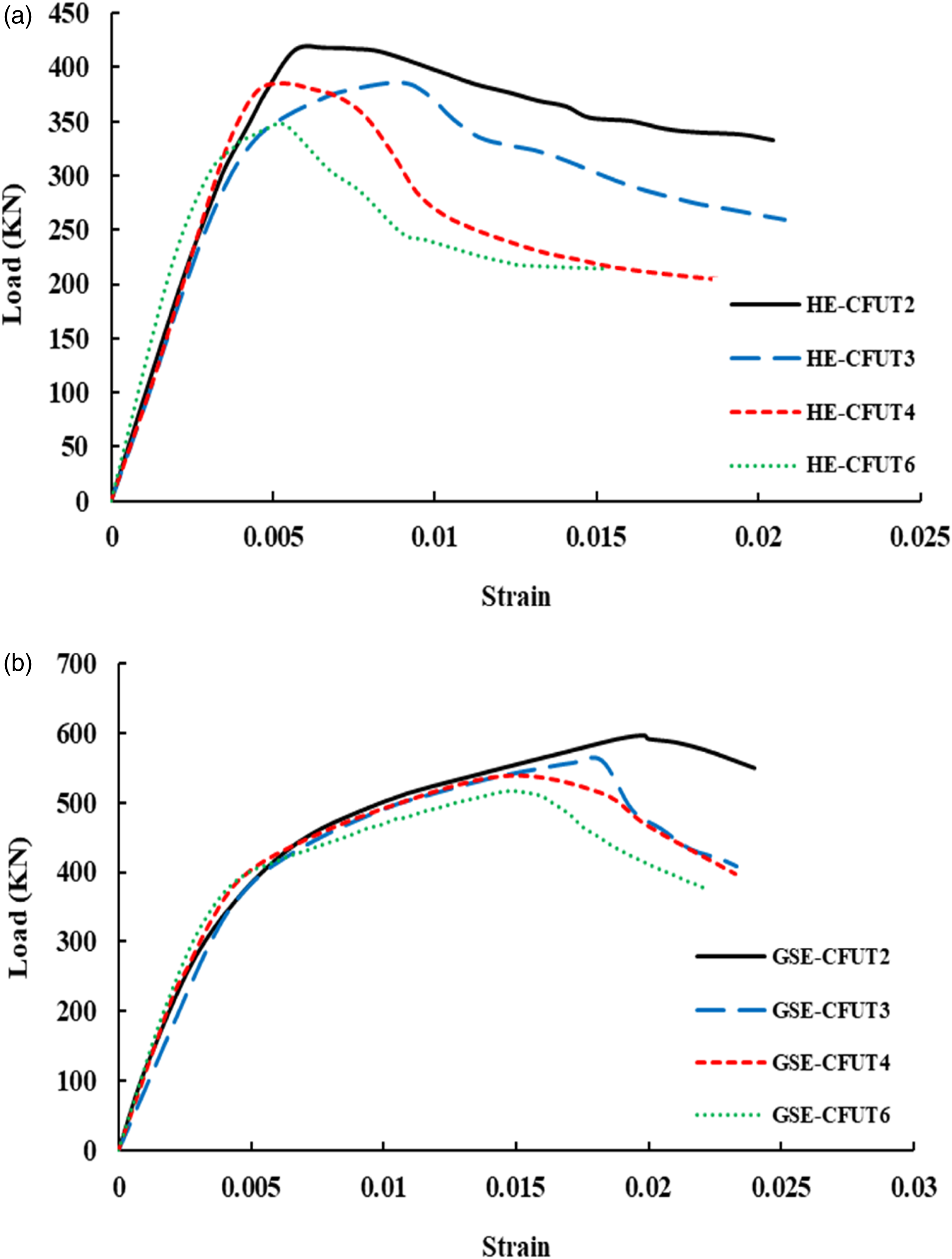
In order to address the effect of the inner hole in composite columns, the compressive behavior of hollow specimens is illustrated in Figure 11. Load-carrying capacity in hollow specimens is slightly lower than in solid ones, which can be attributed to the lower cross-sectional area of hollow columns compared to solid columns. There were no obvious signs of variation in the confinement level as the post-peak behavior and the strain corresponding to the peak load were approximately identical in solid columns and those counterpart hollow ones. The reason for this phenomenon is that due to the special geometric shape of the hollow specimens (concrete ring), concrete is more inclined to dilate outward and, hence, there is a little inward dilation to be constrained. Therefore, it is concluded that hollowness does not influence the overall behavior of CFUT columns. Hollowness effect on the Load-Strain behavior of the (a) Expansive CFUTs; (b) GFRP confined expansive CFUTs.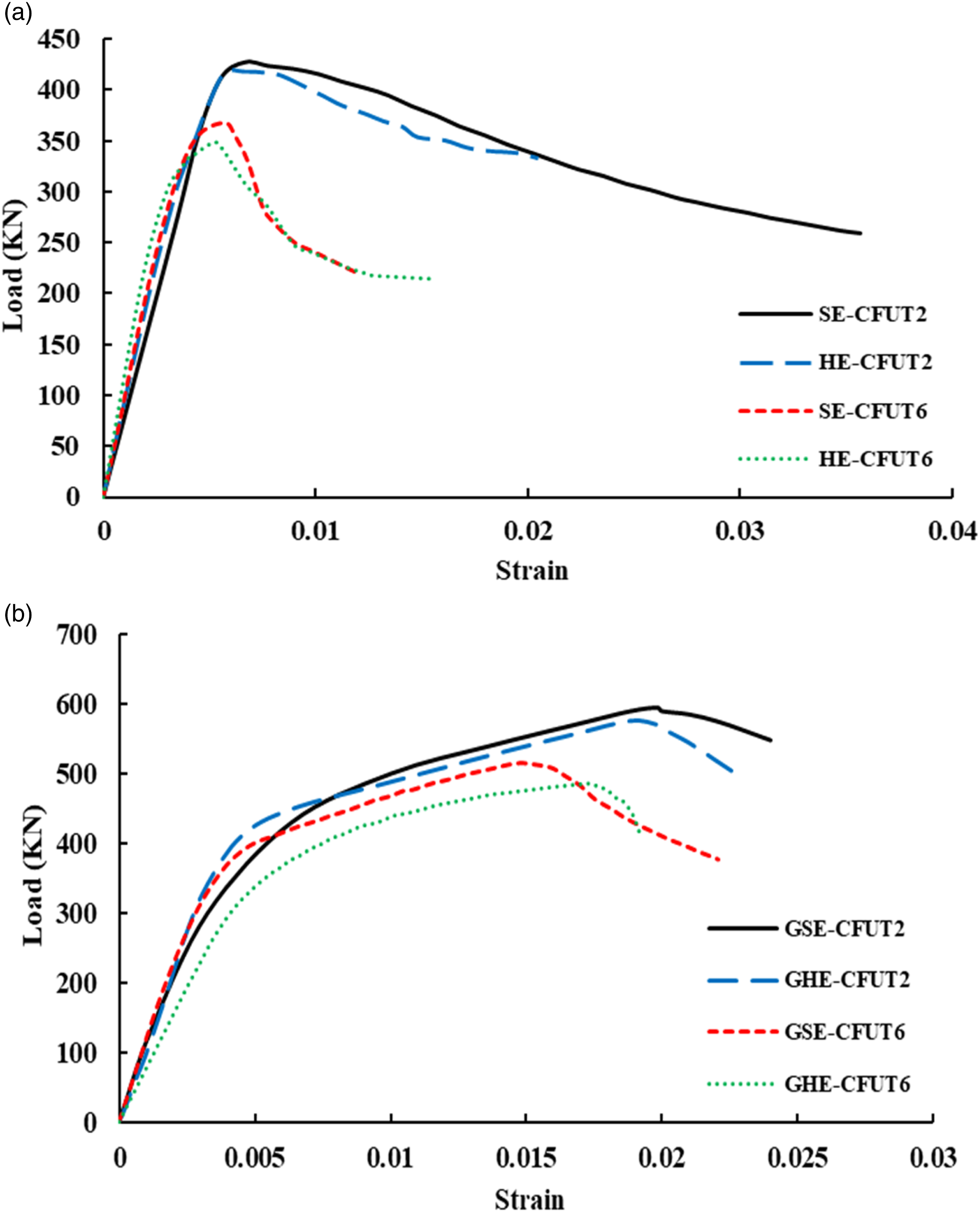
To examine the hollowness effects more quantitatively, Average Compressive Stress (ACS) imposed on concrete 
Concrete average stress-strain curves for solid and hollow specimens are shown in Figure 12. By noting the results of the curves, it was concluded that hollow specimens generally sustained a slightly higher A comparison between Stress-Strain curves of solid and hollow specimens: (a) CFUTs; (b) GFRP confined CFUTs.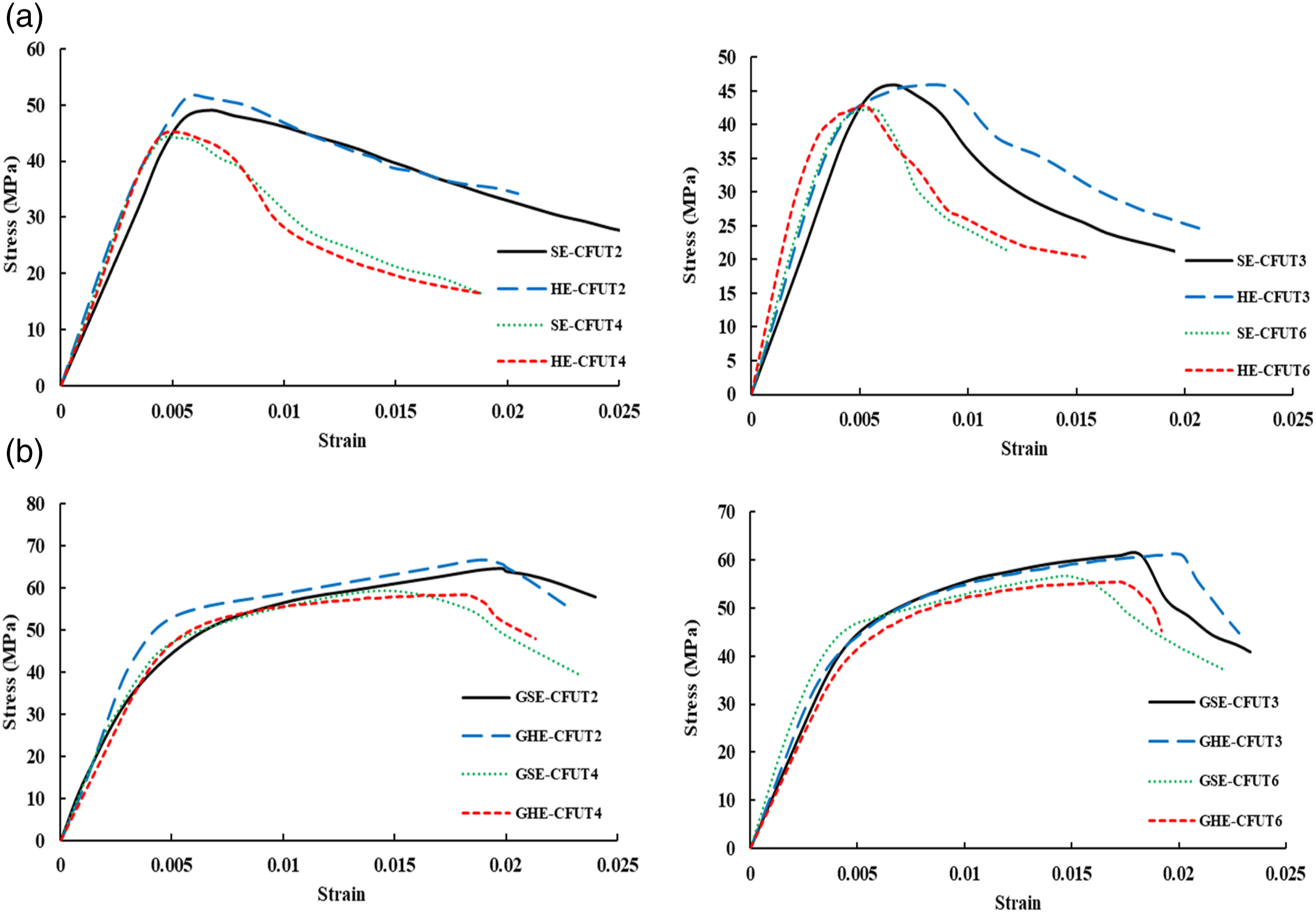
Lateral strain is the key to investigating the confinement action in the circumstances in which confinement applies passively. As the circumferential and radial strains are the same in a circular section, strain gauges were used in the hoop direction at the mid-height of the specimens to obtain the radial deformations indirectly. Figure 13 shows the typical lateral strain curves of the specimens confined with or without GFRP layers, alongside the axial strain curves to demonstrate the general trend of specimen dilation. Generally, the data attributed to the specimen dilation was scattered and mostly did not follow a unique pattern because of shear cracks and local bulging in various locations of the pipe. As is shown, the UPVC pipe allowed the specimens without GFRP wraps to dilate freely even at relatively high lateral strains and no sudden load drop was observed during the loading process. As the confinement was relatively weaker in these specimens, lateral strain increased at a higher rate in comparison with the GFRP confined specimens. In contrast, GFRP wraps kept the specimens tightly and consequently provide higher strength. The dilation was much less in these specimens and the GFRP rupture occurred as the lateral expansion reached near 3% which was the ultimate strain of the GFRP wraps. Typical load V.S lateral strain curve for the specimens.
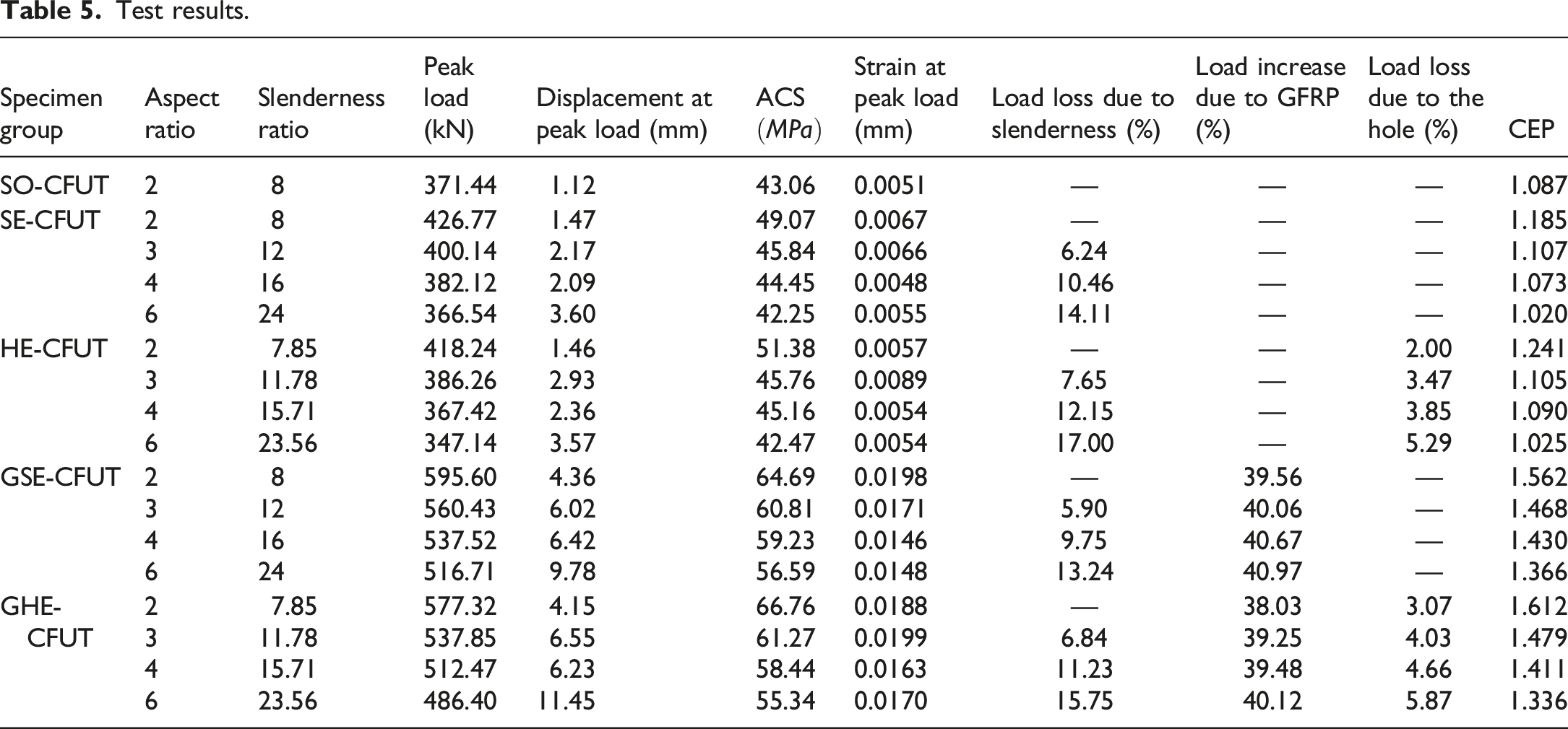
The test results including peak load of the composite columns, displacement, strain corresponding to the peak load, and also the ACS of concrete core are summarized in Table 5. The decrease in load-carrying capacity due to the slenderness is listed with respect to the shortest CFUT specimens of each group. The specimens confined with both UPVC tube and GFRP wraps experienced considerable enhancement in load-carrying capacity compared to that of the specimens confined only with UPVC tubes. Also, the effect of the hole on the value of peak load is presented. As stated previously, hollow specimens experienced a lower peak load in comparison with solid ones. This reduction is quantized in Table 5. In particular, the hollow specimens with higher aspect ratios were observed to have a slightly lower peak load. In order to assess the effects of lateral confinement, the Confinement Effectiveness Parameter (CEP) was defined as the ratio of the ACS of the confined samples over that of unconfined specimen. It can be seen from Figure 14 that the CEP was noticeably higher in GFRP confined samples compared to those only confined with UPVC tubes. Test results revealed that samples with a higher aspect ratio exhibited lower CEP, which can be attributed to the formation of local buckling along the columns’ height. Confinement effectiveness parameter for test samples.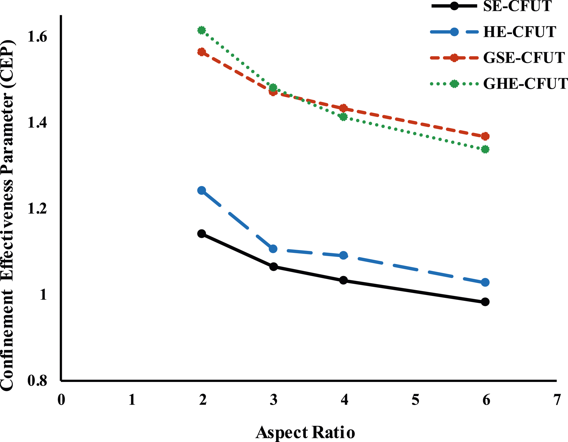
Numerical model and verification
Introduction
In order to evaluate parameters which is not included in the test program, a three-dimensional finite element (FE) model was adopted. Three-dimensional 8-node brick (C3D8R), 4-node shell (S4R) and three-dimensional 4-node membrane elements (M3D4R) were applied for the concrete core, interior/exterior UPVC tubes, and GFRP wraps respectively. The ratio of mesh size over column’s diameter was limited to 0.1 to obtain both computationally efficient as well as desirably precise element size. The schematic views of the simulated specimens and mesh patterns are demonstrated in Figure 15. Schematic mesh pattern in specimens: (a) Solid; (b) Hollow.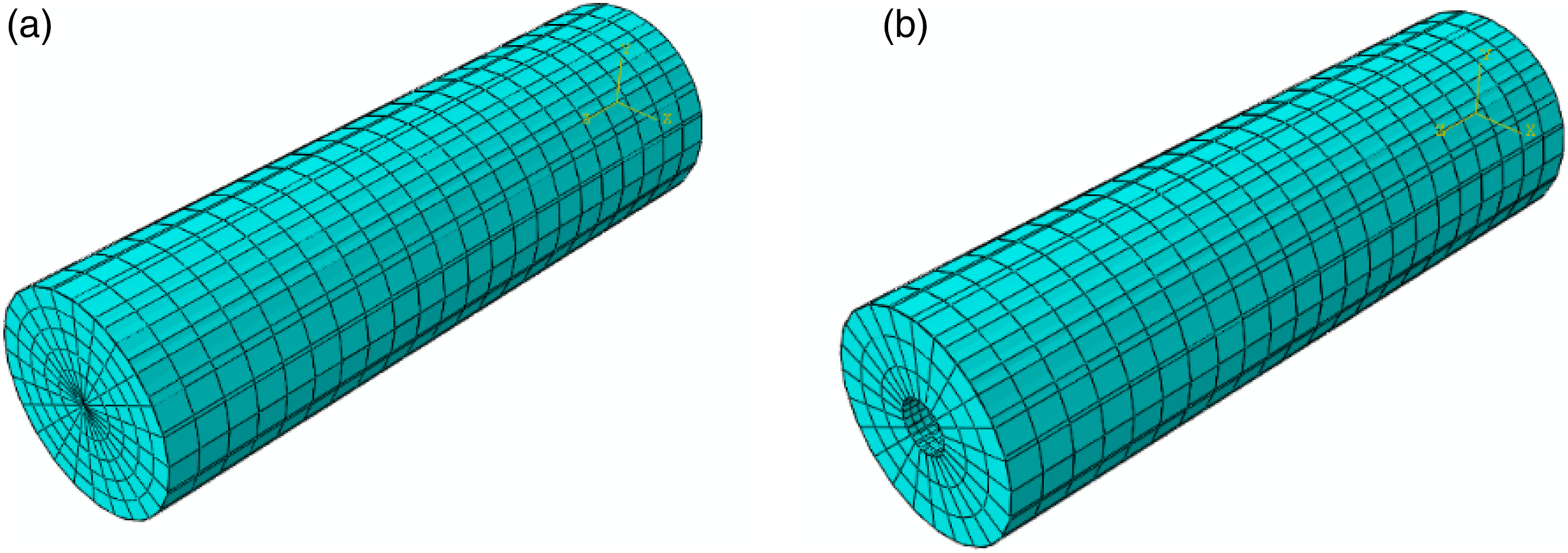
Since neither UPVC tube nor concrete core penetrates each other, the interaction between them was set to be hard contact in the normal and penalty in the tangential direction,21,22 though the coefficient of friction was observed to have negligible effect on the results. Hard contact interaction enables the separation of two surfaces in a stretching mode while simultaneously preventing their penetration into each other under compression. Moreover, tie interaction was assumed for the interface between the GFRP wraps and the UPVC pipe in which premature failure of epoxy-resin and the slippage of materials was ignored. Tie interaction has been also used in literature to model the interface between the outermost surface of inner materials (UPVC in this study) and FRP composites.23–25 The bottom of the columns was restrained in all translational degrees of freedom and displacement-control load was implemented monotonically at the top surface of the composite columns.21,24,25
Constitutive models
For the numerical analysis, all engineering stress-strain data were converted to true ones using equation (7).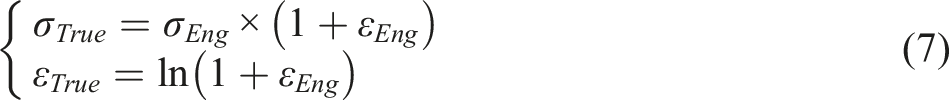
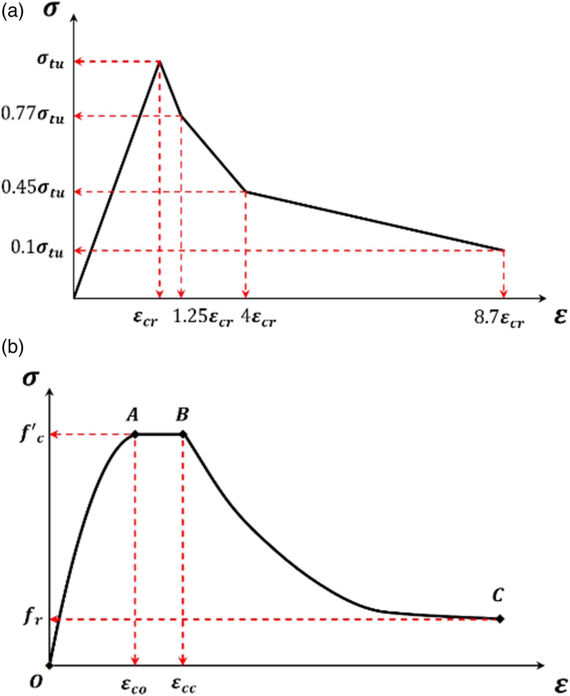
The behavior of confined concrete was simulated using Concrete Damage Plasticity (CDP). The modified Nayal and Rasheed model
26
was used for the tensile behavior of the concrete core in which instead of a harsh drop, a softening stage is considered as Figure 16(a) to make a more executively appropriate model.
27
In compression, a three-staged model is proposed and used for the confined concrete which is shown in Figure 16(b). Kent and Park model
28
for unconfined concrete was taken into account to describe the onset of the compressive curve (OA) since the confining interaction is not activated yet. AB region was defined based on Samani and Attard’s formulation
29
in which confinement controls the post peak branch as follows: (a) Tensile stress-strain behavior of concrete; (b) Compressive stress-strain behavior proposed for confined concrete.


The elastic-plastic behavior for the UPVC pipe was considered during the analysis. The stress and strain values were accurately calibrated from engineering to true values to obtain precise measurements, leading to obtaining the elastic-plastic behavior exhibited by the UPVC pipe. Tensile stress-strain curve of Figure 3(c) was used for modeling of the pipe. However, the compressive parameters of the UPVC tube were assumed identical to those of tensile behavior in the range of applied displacements. GFRP layers were considered linearly elastic in tension with the mechanical properties of Table 4. The failure criteria for FRP were determined using the “fail stress” option available in ABAQUS, with consideration given to various factors such as longitudinal tensile and compressive strength, transverse tensile and compressive strength, and shear strength. These criteria have been widely utilized in previous studies.21,24,25
Model verification
Failure patterns
The failure patterns and stress distribution in numerical simulations and those of experimental tests were compared, as illustrated in Figure 17. Simulated failure patterns obtained in this analysis are according to the values of von Mises stress and plastic strain contours available in ABAQUS. According to Figure 17(a) and (b), it can be observed that the failure modes obtained from numerical simulations match desirably with experimental ones. Similar to the test results, the short columns confined with both UPVC tube and GFRP wraps experienced a high stress level near the top surface of columns (loading end), as shown in Figure 17(a). This leads to the complete longitudinal rupture of the GFRP wrap and the UPVC pipe called the zipping effect. Long columns demonstrated a high stress level as well as bulging near the supporting end, similar to that observed experimentally in Figure 17(b). Also, the FE prediction indicates a high tensile strain near the outer part of the composite column’s cross-section as presented in the previous sections. Failure and crack patterns for experimental tests and corresponding numerical simulations: (a) Stress distribution and GFRP rupture; (b) Stress distribution and drum-shaped bulge.
Load-displacement responses
The FE analysis was carried out to obtain a numerical model predicting the behavior of specimens under the monotonic compressive loading. FE results are depicted in Figure 18. By observing the results, it is clear that a desirable agreement was acquired between experimental and numerical results in reference to the general behavior as well as the accuracy of the values. Load-strain curves of the test specimens V.S. the simulated specimens.
Conclusions
This paper performs an experimental study and a numerical investigation on the behavior of solid and hollow expansive concrete-filled UPVC tube columns under the monotonic compression. For this endeavor, 32 expansive CFUT specimens with different aspect ratios categorized into four groups plus two ordinary CFUT companions were cast and tested, a verified finite element model was proposed and based on the results, the followings were concluded: 1. The use of expansive concrete as an infill material in lieu of ordinary concrete enhanced the strength by up to 15%, as well, increased the ductility dramatically by 70%. The expansive agent, while compensating shrinkage of concrete, provided better interaction between the tube and the concrete core. 2. Both peak load and its corresponding axial strain reduced with an increase in the height of specimens from 220 mm to 660 mm within a range of 7 to 26 and 14 to 17%, respectively. 3. Load-carrying characteristics of the expansive CFUT specimens were considerably improved by using two layers of GFRP wraps. In particular, peak load increased noticeably by 38 to 41% due to the GFRP confinement. This increase was also higher in longer specimens. 4. The presence of the hole did not affect the confinement level due to the specific geometric shape of hollow specimens (concrete ring) since the concrete is more inclined to dilate outward. Hollow specimens generally sustained a slightly higher average compressive stress compared to solid ones. This can be attributed to the specific pattern of stress distribution on the concrete cross-section in which stress was relatively higher near the periphery. The confinement effectiveness was more noticeable in GFRP confined samples compared to those only confined with UPVC tubes. 5. For further investigations, a theoretical model for the behavior of confined concrete was proposed and implemented in FE software 6. An increase in the number of GFRP layers demonstrated significant performance improvement of composite columns in which the peak load and its corresponding strain increased. By considering the results, it was realized that the ultimate load capacity improved approximately in equal quantities by an increase in the number of GFRP layers. 7. It was demonstrated that by increasing the hole diameter, the peak load of composite columns reduced. As well, the confinement ratio grew with an increase in the diameter of the hole, which resulted in a less steep post-peak behavior.
Footnotes
Acknowledgements
The authors are grateful to the center of excellence in Composite Structures and Seismic Strengthening for partially supporting this research project. The authors also would like to thank the strong floor, concrete, and UTM laboratories of the Sharif University of Technology for accommodating the use of the equipment and facilities, and the Vinoplastic Company for providing the UPVC pipes. A special thanks to Reyhaneh Vardast who assisted responsibly through experimental tests and her help in the preparation of this paper.
Declaration of conflicting interests
The author(s) declared no potential conflicts of interest with respect to the research, authorship, and/or publication of this article.
Funding
The author(s) received no financial support for the research, authorship, and/or publication of this article.