
Abstract
Helicoidal composite has been found naturally existing in many species of crustaceans and it has recently raised a significant amount of interests among researchers due to its great impact performance resulted from unique fiber layup architecture. This work is focused on developing a novel bio-inspired helicoidal thermoplastic composite and studying its mechanical behaviors under different testing conditions. Continuous glass fiber reinforced polypropylene composite preforms were used for compression molding the helicoidal structure with a pitch angle of 16.3° and nonlinear pitch angle. Composites with conventional fiber layups such as 0/90 and quasi-isotropic layup sequences were also prepared and tested for comparison purpose. Various tests at different strain rates, including quasi-static test (flexural test and compression after impact test), low strain rate test (Izod impact test and drop tower impact test), and high strain rate test (Split Hopkinson pressure bar test), were performed to evaluate the mechanical properties of the helicoidal composites and conventional composites. The helicoidal composites showed twisting fracture pattern for deflecting cracks involving more areas for energy absorption in addition to common failure mechanisms in the Izod impact test. It was also found that the helicoidal composite showed considerably higher damage tolerance than the conventional composites in high strain rate scenarios.
Keywords
Introduction
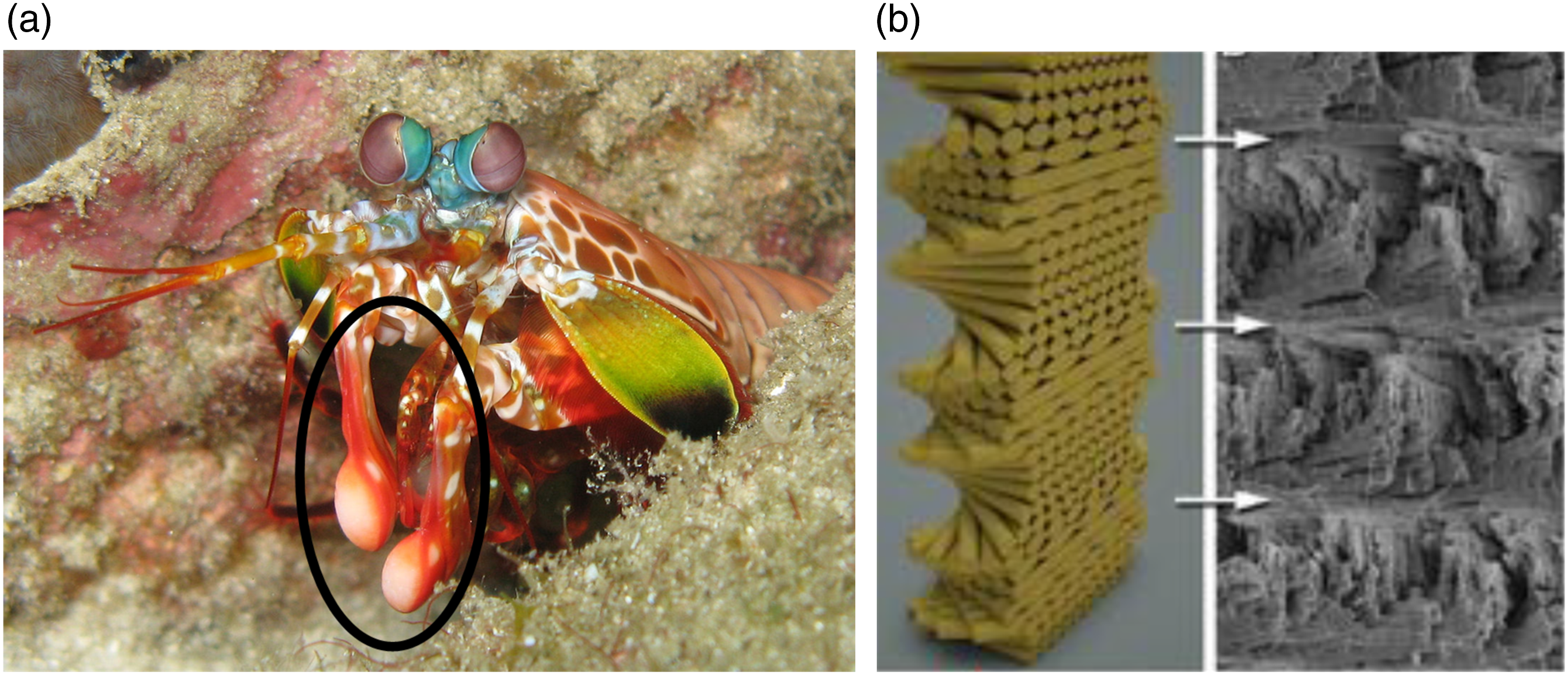
Helicoidal composite structure has been commonly found in many species of crustaceans, such as mantis shrimp,1–5 lobster,6,7 beetle, 8 crab, 9 etc. It has a unique construction in that the fiber angle in the composite gradually changes throughout layers. Because of the unique construction, the helicoidal composite has shown excellent performance in impact. The crustaceans have taken advantage of the excellent impact performance of the helicoidal composite structure in their claws or clubs.1,2 to break the shells of their preys, such as snails and clams. It is reported that the dactyl club of mantis shrimp (Odontodactylus scyllarus) has the helicoidal composite structure and can withstand an extremely high impact velocity of up to 23 m/s and an acceleration up to 10,400 G repeatedly, 5 making it one of the most impact-resistant natural materials.
Research work from different groups have reported the helicoidal composite structure in the dactyl club.1–4 The natural helicoidal composite consists of high strength chitin fiber (reinforcement) and hydroxyapatite (matrix) and the orientation of the chitin fiber in each layer varies gradually through the composite layers. Figure 1(a) shows the dactyl club of peacock mantis shrimp and Figure 1(b) displays both the schematic and micrograph of its helicoidal composite structure with a gradual fiber angle change from layer to layer.
2
It has been found that the angle shift between adjacent layers, defined as pitch angle, results in a smooth change in the in-plane stiffness and reduced interlaminar shear stresses. The unique fiber layer arrangement in the helicoidal structure also deflects crack propagation and amplifies the volumetric material per unit required for the crack propagation, both of which considerably help dissipate energy efficiently and thereby limit damage through the structure.
10
Biomimetic composite structures inspired by the naturally helicoidal composite have been constantly developed by researchers.11–15 Some of the work used the 3D printing approach to achieve the helicoidal structure. Raney et al. 16 used ink made of short carbon fiber and epoxy and a rotating nozzle to print helicoidal composites with controlled fiber orientation, microstructural complexity, and good damage tolerance. Liu et al. 17 printed helicoidal composites with different pitch angles and found that the helicoidal composite can divert cracks and prevent formation of critical transverse cracks that were observed in conventional composites. Yang et al. 12 manufactured helicoidal carbon nanotube reinforced composites using electrically assisted 3D printing and found that helicoidal composites with a small pitch angle led to great impact resistance. Wang et al. 18 printed short carbon fiber reinforced nylon composite into helicoidal structures by taking advantage of the fiber alignment from extrusion during printing. Although 3D printing is an intuitively obvious approach to produce helicoidal structures and its excellent tailorability has allowed researchers print helicoidal structures with complex geometries and intricate fiber orientation arrangements, most of the printed structures have very limited performance due to the low mechanical properties of the feedstock material.17–19
Besides 3D printing, vacuum or autoclave molding of thermoset matrix composite based helicoidal structures have also been developed to produce helicoidal composite structures.20,21 Because of continuous fibers used in the studies, those helicoidal structures possess great impact performance. Abir et al. 20 molded helicoidal structures using carbon fiber reinforced epoxy matrix composites and studied their impact performance. It was found that the helicoidal composite was able to dissipate impact energy through large delamination compared to more concentrated damage area in conventional cross-ply and quasi-isotropic composites. 20 Carbon fiber epoxy based helicoidal composite structures were also manufactured in an autoclave and tested under low velocity impact. 3 Compression after impact (CAI) test was performed on the composite and the testing results showed that the damage area in the helicoidal composite structure is more than that in the conventional composites. However, the CAI residual strength of the helicoidal structure did not show advantage over the composite with cross-ply or quasi-isotropic layup sequences because of the higher degree of perforation in the helicoidal structure. 3 Cheng et al. studied the mechanical behavior of helicoidal structures using S2-glass reinforced epoxy matrix composites produced from a vacuum bagging method and found that the helicoidal structure had better residual strength from retesting the tested short beam samples. 22 Grunenfelder et al. 4 also molded carbon fiber epoxy composite based helicoidal structure using the vacuum bagging method and found that there was less damage propagation through the thickness but more in-plane damage in helicoidal composite samples compared to the composites with conventional fiber layup sequences. 4
Most of the research studies have been focused on using discontinuous fiber reinforced composite materials and continuous fiber thermoset matrix composites for developing biomimetic helicoidal composites so far. This research work is mainly aimed at using continuous fiber reinforced thermoplastic matrix composite as the material to develop novel bio-inspired helicoidal thermoplastic composite for their great fracture toughness, superior impact resistance, lightweight characteristic, cost-effectiveness, recyclability, etc.23–25 Compression molding was used to produce the composite samples in this work for their ability to consolidate continuous fiber thermoplastic composites. Various tests at different strain rates, including quasi-static test, low strain rate test, and high strain rate test, were performed to evaluate the mechanical properties of the helicoidal composites and conventional composites. The mechanical behaviors of the thermoplastic composite based helicoidal structures are investigated and compared with those of conventional composites.
Materials and methods
Density and mechanical properties (0° direction) of unidirectional glass fiber reinforced polypropylene composite preform. 26
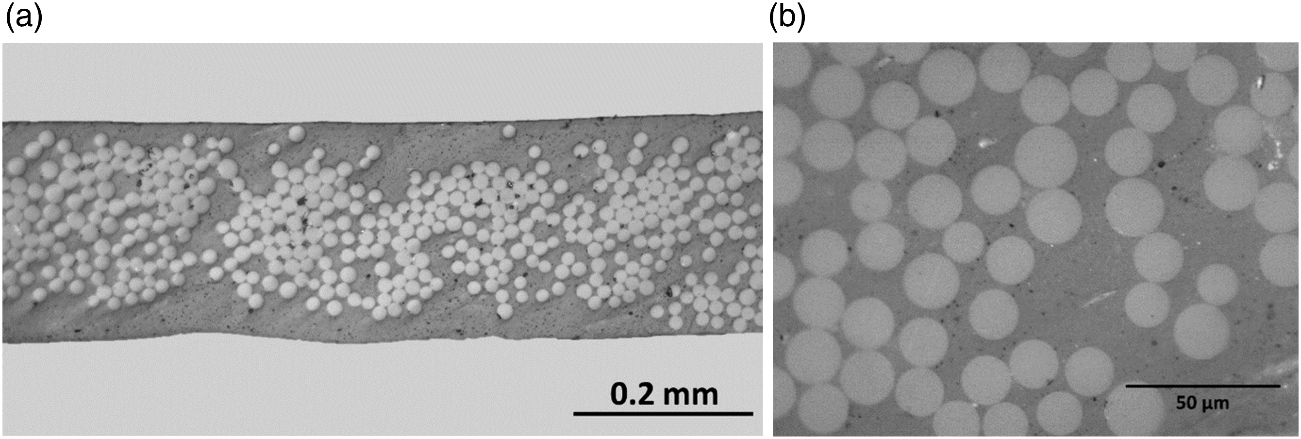
(a) Cross-sectional view of the unidirectional fiber reinforced polypropylene composite preform used for developing bio-inspired helicoidal composites; (b) a closer view of the preform showing glass fibers embedded in polypropylene matrix.
Differential scanning calorimetry (DSC) was used on the composite preform to evaluate its thermal behavior. A heat-cool cycle (20°C/min heating and cooling rate) was run using TA Q100 DSC. The DSC curve of the composite preform in Figure 3 shows that the melting temperature of the matrix in the composite is about 165°C. The processing temperature for compression molding bio-inspired continuous fiber reinforced thermoplastic composites was determined based on the melting temperature from the DSC curve. DSC curve showing the melting point (165°C) of the polypropylene matrix in the composite preform.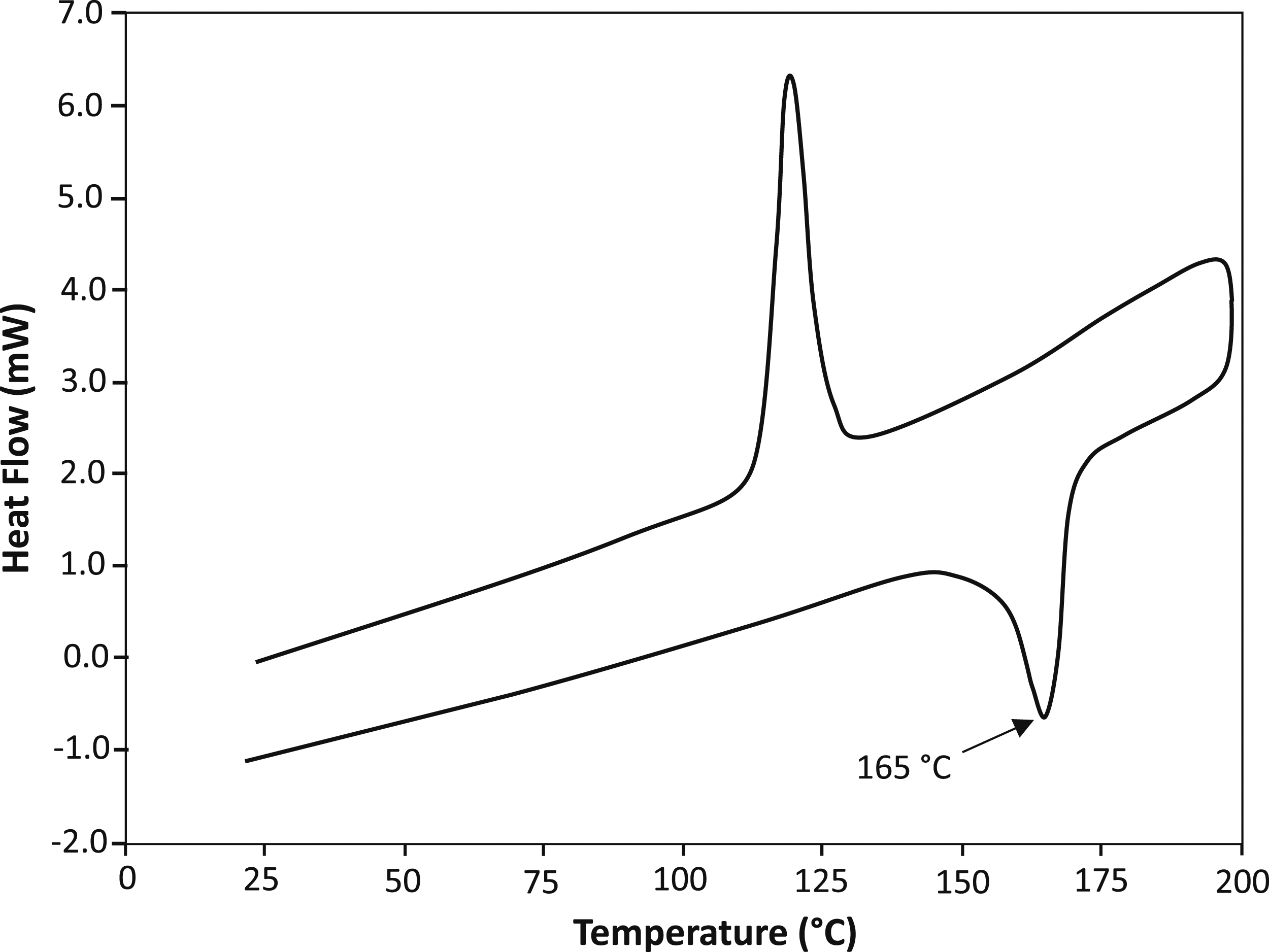
Layup sequences of continuous glass fiber reinforced polypropylene composites.
Figure 4 shows the stacked composite preform in a cascade fashion prepared for compression molding for each layup sequence, i.e. 0/90 (Figure 4(a)), Quasi-iso (Figure 4(b)), Helic-16.3 (Figure 4(c)), and Helic-asym (Figure 4(d)). All the composite preforms have a dimension of 305 mm x 305 mm (12” x 12”). The preforms in the helicoidal composite layup show the gradual fiber angle change from one layer to the next layer. Glass fiber polypropylene composite preforms in a cascade fashion with (a) cross-ply 0/90 layup, (b) quasi-isotropic layup, (c) helicoidal-16.3° layup, and (d) helicoidal-asymmetric layup for compression molding. All the composite preforms have a dimension of 305 mm x 305 mm (12” x 12”).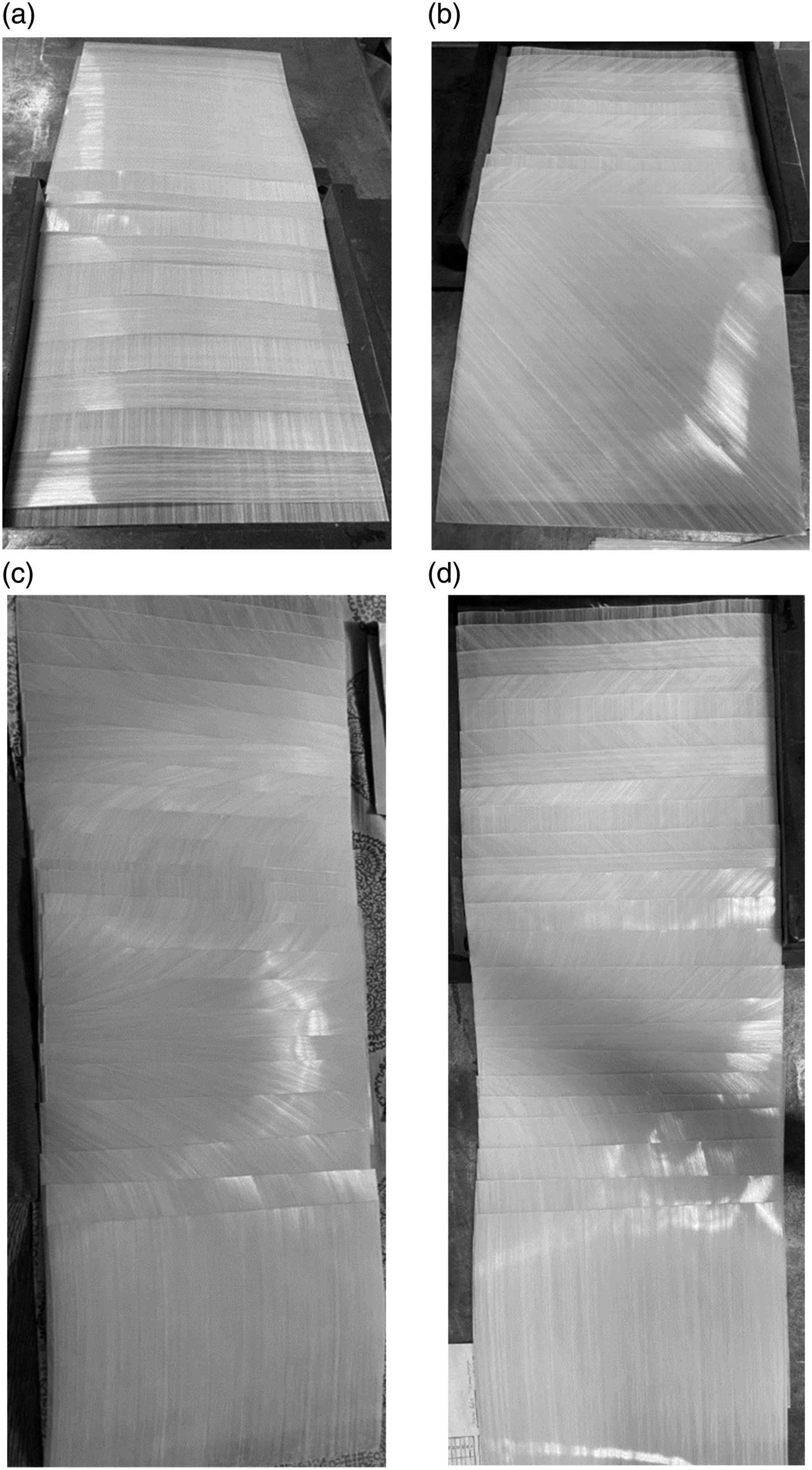
Compression molded composite samples were prepared, polished, and examined under microscope. Figure 5 shows the cross-sectional view and partial fiber layer arrangement of the composite with different fiber layup sequences: Figures 5(a)–0/90 layup sequence, Figure 5(b)—quasi-isotropic layup sequence, Figure 5(c)—helicoidal structure with 16.3° pitch angle, and Figure 5(d)—helicoidal structure with asymmetrical layup. The samples show relatively good consolidation in spite of some voids observed. It is confirmed that the fiber architecture was maintained for each composite during the compression molding process. Micrographs of composites with (a) 0/90 layup sequence; (b) quasi-isotropic layup sequence, (c) helicoidal structure with 16.3° pitch angle; and (d) helicoidal structure with asymmetrical layup.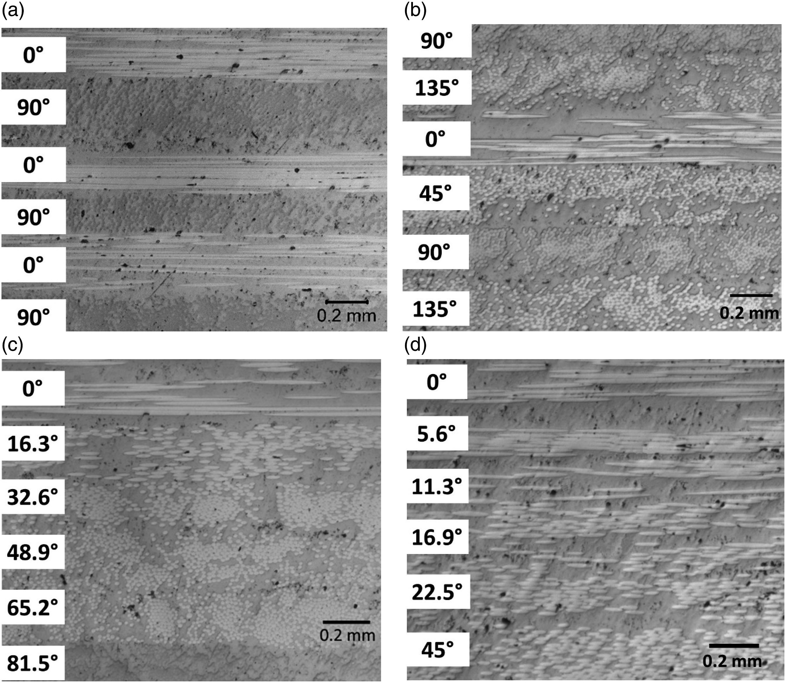
Samples for quasi-static tests (flexural test and compression after impact test), low strain rate tests (Izod impact test and drop tower impact test), and high strain rate test (split Hopkinson pressure bar test) were prepared from the compression molded composites.
Results and discussion
Various tests were conducted to evaluate the performance of the bio-inspired helicoidal composites and the composites with conventional layup sequences. The mechanical behaviors of those composites were presented and discussed below.
Flexural testing
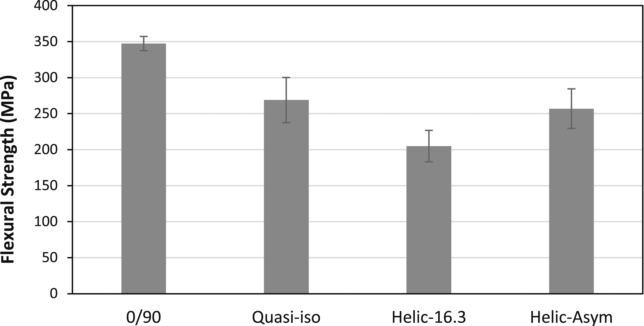
Three-point bending test was carried out in accordance with ASTM D790 - Standard Test Methods for Flexural Properties of Unreinforced and Reinforced Plastics and Electrical Insulating Materials using an Instron model 1331 Servo Hydraulic Material Test System. Five specimens were prepared from each composite and tested according to the standard. Load and displacement were recorded for each specimen. Flexural strength of the composite was calculated based on the equation (equation (1)) below. Comparison of flexural strength among the composites with different layup sequences.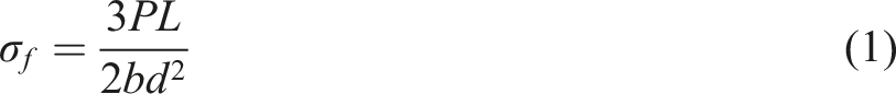
Izod impact testing
Izod impact testing was carried out based on ASTM E23- Standard Test Methods for Notched Bar Impact Testing of Metallic Materials using an Tinius Olsen tester. Five unnotched specimens were prepared from each composite and tested and the energy absorbed was recorded. Figure 7 compares the impact strength of each composite. The impact strength of the continuous glass fiber PP composite has an impact strength of more than 320 kJ/m2 which is significantly more than the impact strength of 3D printed helicoidal composite samples.18,28 The comparison shows that the 0/90 sample possessed superior impact performance while the quasi-isotropic and asymmetric layups performed similarly. The superior impact performance of the 0/90 sample is probably attributed to a larger percentage of fibers aligned in the sample length direction, which is more efficient for energy absorption through fiber breakage in the composite. This is in agreement with the trend observed in the flexural testing. Comparison of impact strength for the helicoidal and conventional composites in Izod impact testing.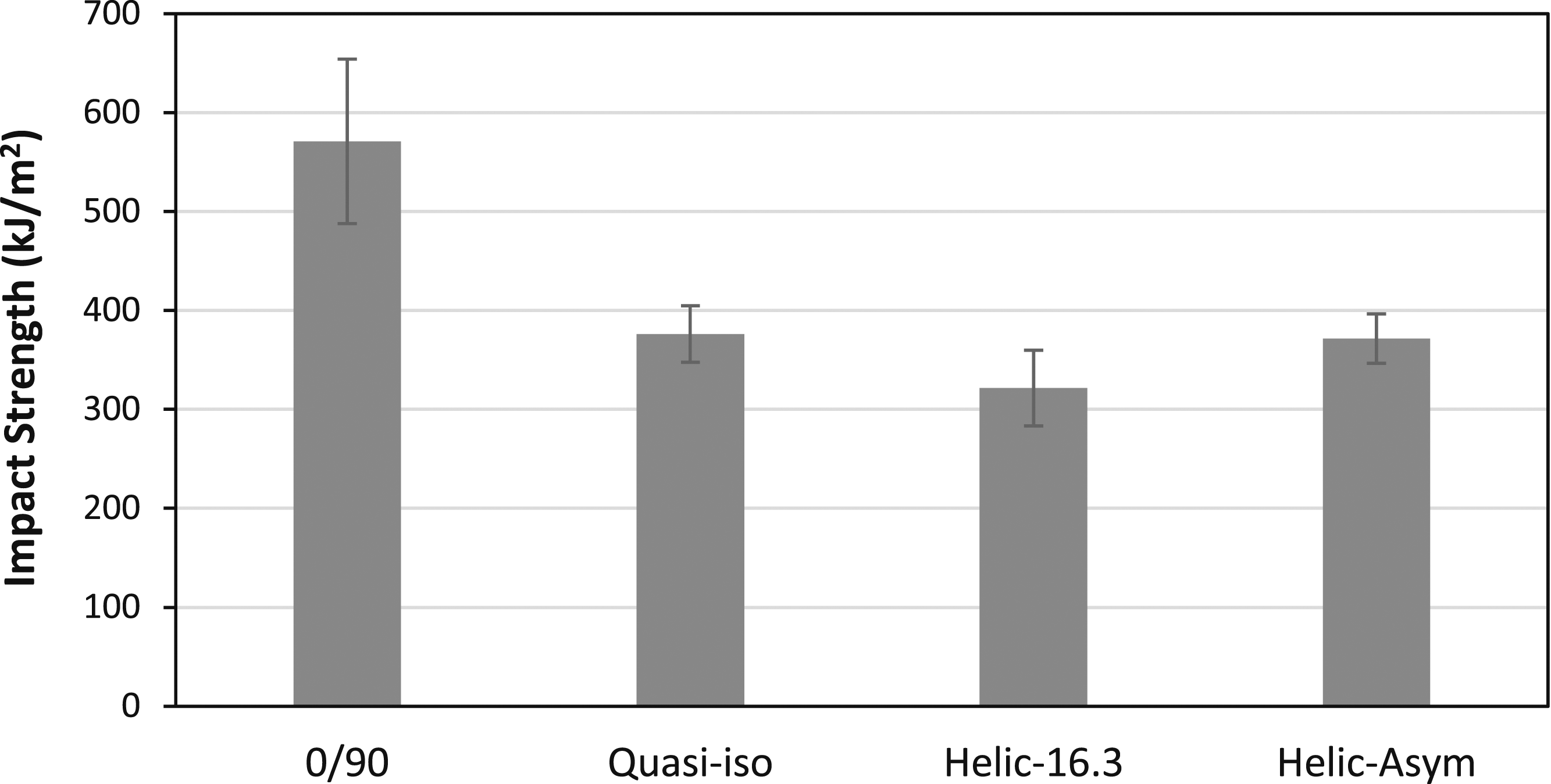
The tested samples were characterized on their failure mechanisms under a confocal microscope. Figure 8 shows the macrographs of the fractured region of each composite. All of the composites showed general failure mechanisms including fiber fracture, matrix fracture and delamination between layers. Those are the typical failure mechanisms that have been found in other research work to absorb impact energy in thermoplastic composites.29–31 Figure 8(a) shows that the cross-ply 0/90 sample had cleaner fracture compared to other composites. In Figures 8(c) and 8(d), helicoidal composites samples showed twisting fracture pattern, indicating that cracks were forced to follow a tortuous path and more areas were involved in energy absorption. However, the benefit of having more tortuous path and more areas involved for energy absorption did not overcome the drawback resulted from less fibers being perpendicular to the loading direction. One possible reason is due to the low shear strength of the polypropylene matrix in the composites. Although more areas were involved in energy absorption in the composite, the low shear strength resulted in low fracture toughness, which did not improve the energy absorption capability for the helicoidal composite. The images of fracture surface of composites with different fiber layup sequences: (a) 0/90 layup sequence; (b) quasi-isotropic layup sequence, (c) helicoidal structure with 16.3° pitch angle; and (d) helicoidal structure with asymmetrical layup. Note the twisting fracture pattern in the helicoidal composite.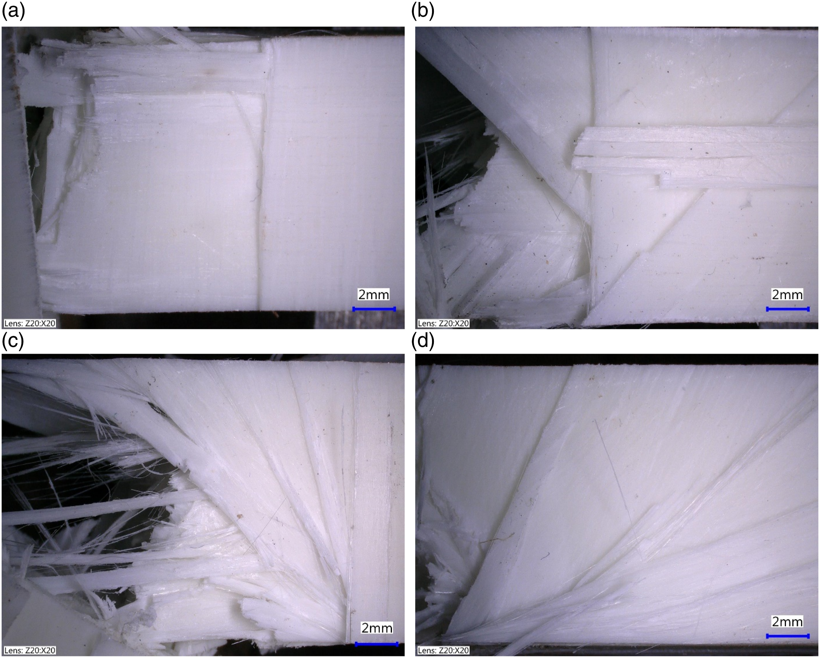
Drop tower testing and compression after impact testing
Drop tower impact test was performed according to ASTM D7136 - Standard Test Method for Measuring the Damage Resistance of a Fiber-Reinforced Polymer Matrix Composite to a Drop-Weight Impact Event using a Dynatup drop tower with a 13.1 kg mass free falling from a height of 77.8 cm. A 16 mm diameter hemispherical impactor was used for the impact testing. The drop height and weight resulted in an impact velocity of around 4 m/s and an impact energy of around 100 J. The comparison of average energy absorption in different composites in Figure 9 showed that the 0/90 sample absorbed the most energy among all the composites. The helicoidal-asymmetric sample performed like the quasi-isotropic sample but with greater variability. Comparison of absorbed impact energy by composites with different layup sequences in drop tower testing.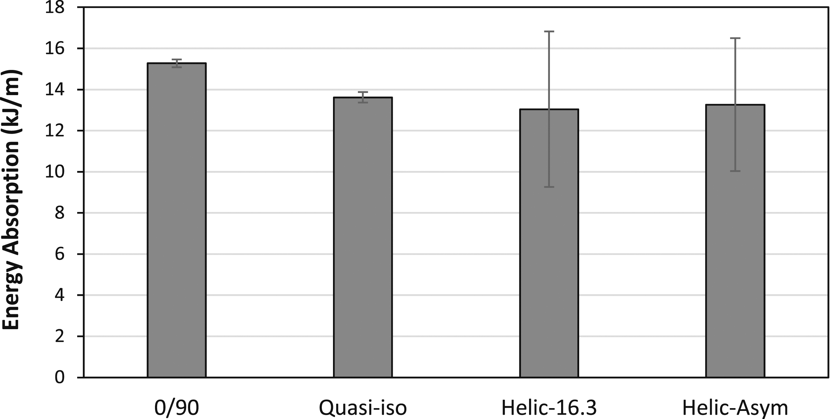
Compression after impact (CAI) test was carried out on the post-impact composite by following ASTM D7137 - Standard Test Method for Compressive Residual Strength Properties of Damaged Polymer Matrix Composite Plates to measure compressive strength to failure for damaged composite panels. The 0/90 composite performed best (Figure 10) though not much differentiates any of the material layup sequences. Large standard deviations occurred probably due to the large variation in stresses when stress concentration occurred to the damage area. Residual compression strength results showing similar performance among different composites.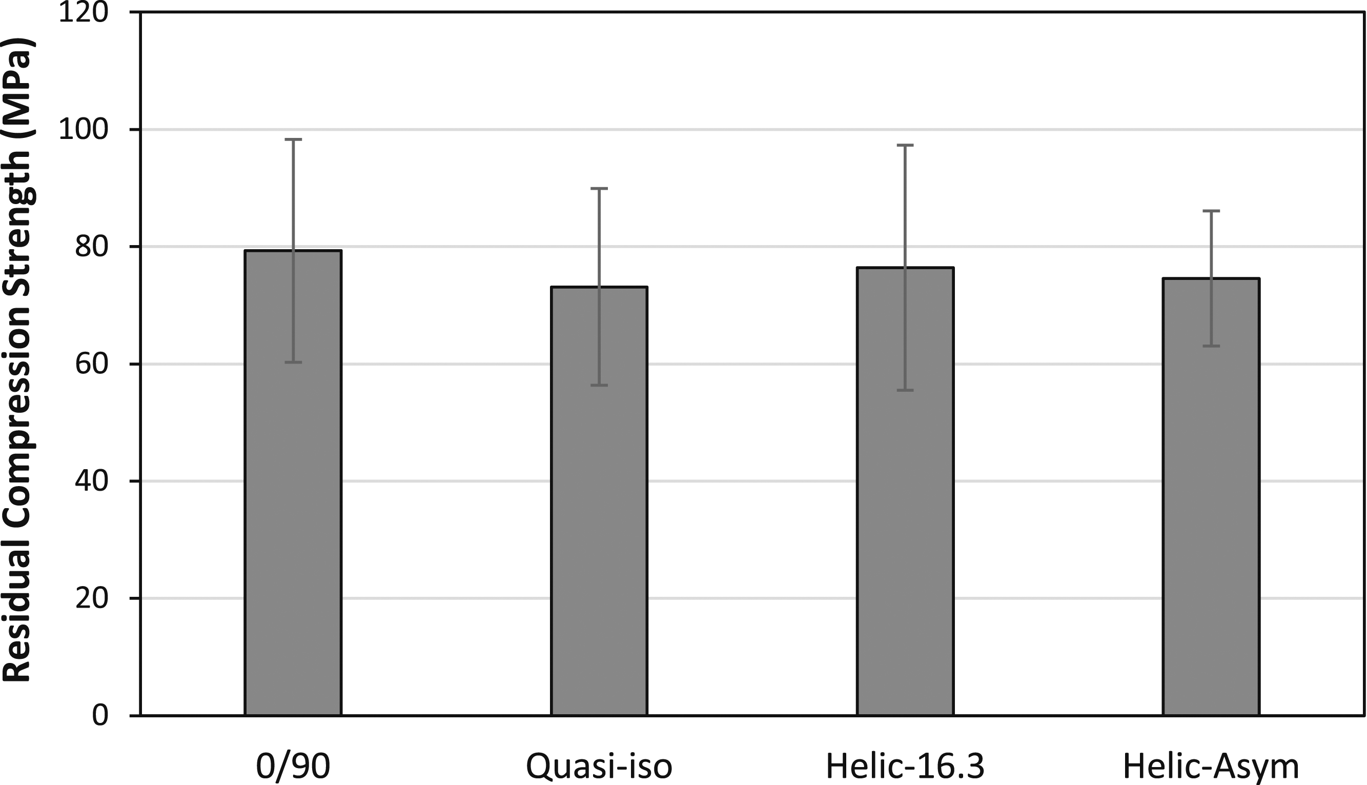
Split hopkinson pressure bar test
Split Hopkinson pressure bar (SHPB) is an apparatus that can achieve a strain rate of more than 1000 s−1. Compared to the previous tests performed in this work, SHPB test can facilitate evaluation of the performance of the composites with different layup sequences at a much higher strain rate. Among all the tests used in this work, the strain rate in SHPB test is the closest to the actual strain rates experienced in the dactyl club of mantis shrimp during impact. Therefore, SHPB test was used to evaluate the mechanic behavior and performance of the bio-inspired helicoidal composite. Twelve-mm-diameter samples were prepared from the composites. Different shot pressures, i.e. 103 kPa (15 lbf/in2), 138 kPa (20 lbf/in2), and 172 kPa (25 lbf/in2) were used. Figure 11 shows the stress-strain curve of each composite for 103 kPa and 172 kPa shot pressure. The stress-strain curves for the composites with different layup sequences at (a) 103 kPa (15 lbf/in2) and (b) 172 kPa (25 lbf/in2) shot pressure.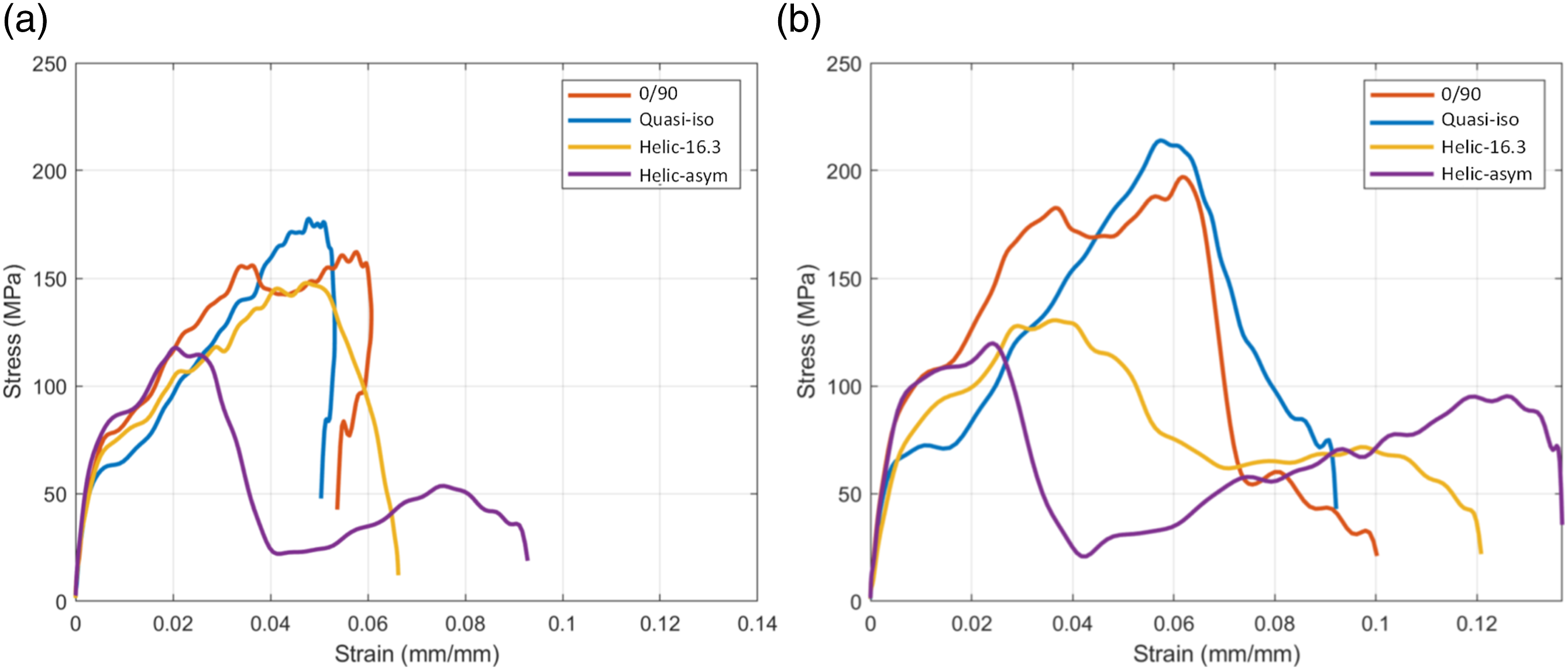
The helicoidal composite structures showed a lower peak stress compared to the conventional structure (Figure 11(a)), however, their strains after the peak stress were larger. Between the two helicoidal structures, the asymmetrical helicoidal structure showed less peak stress but higher strain. The asymmetrical helicoidal structure also had a second peak with the peak stress of around 50 MPa at the strain of around 0.075 mm/mm. Figure 11(b) compared the stress-strain curves for the composites with different layup sequences at 172 kPa (25 lbf/in2) pressure. The curves indicated the same trend shown in Figure 11(a). Both the helicoidal structures had lower peak stresses but higher strains. The helicoidal structures also showed increasing strain after the peak stress, indicating that the impact energy can be dissipated with a larger strain or in a longer time. This is significant for the dactyl club with a helicoidal structure in that a lower stress is resulted in the helicoidal structure from the impact and it induces less possibility of damage to the helicoidal structure or injury to the dactyl club. The asymmetrical helicoidal structure also showed a second peak, indicating the capability of continuously bearing more load in the structure after the first peak stress.
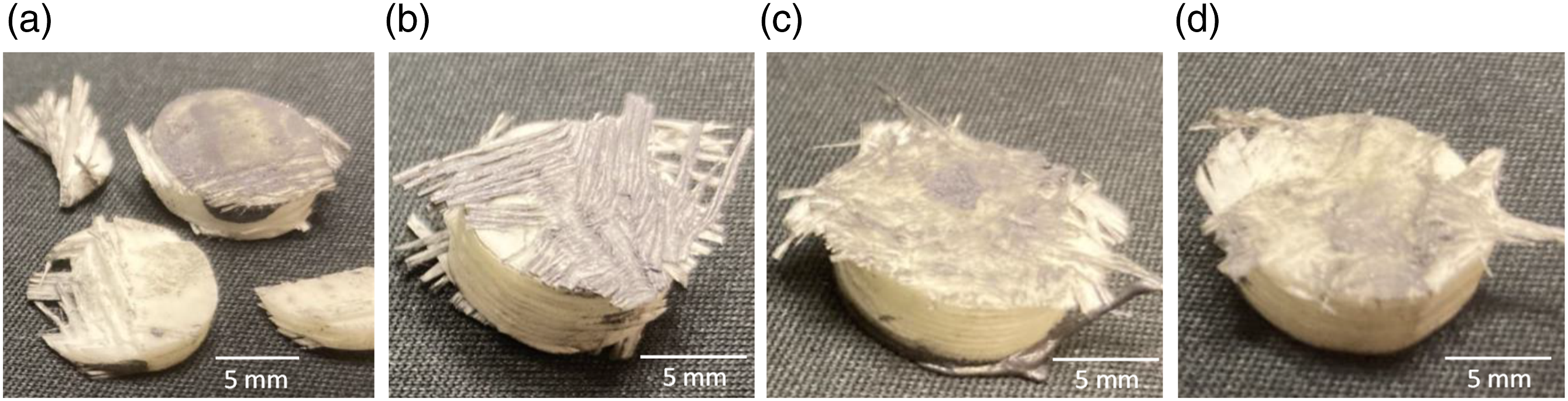
The specific toughness before and after peak stress were evaluated for each composite and compared among all the composite layups. The specific toughness is defined as integration of the area under the stress-strain curve and has a unit of Pa or J/m3 (energy/material volume).32,33 Figure 12 shows the specific toughness before and after the peak stress. It was found the composites with conventional layups had higher specific toughness before peak stress than the helicoidal composites at any specific shot pressure. However, the helicoidal composites showed better toughness after peak stress than the conventional composites, indicating that the helicoidal composite has the capability of load carrying capability after the peak stress and is able to withstand damage better than the conventional composites. The trend is also in agreement with the amount of damage observed in the tested samples. Figure 13 shows the composite samples after the SHPB test with 172 kPa (25 lbf/in2) shot pressure. The 0/90 composite showed the most damage while the helicoidal composite samples showed least amount of damage. This is in favor of animals such as mantis shrimp using dactyl club made of helicoidal composites in high strain-rate scenarios for damage mitigation. Specific toughness (a) before and (b) after peak stress for the thermoplastic composites with different layup sequences. (a) 0/90, (b) Quasi-iso, (c) Helic-16.3, and (d) Helic-asym composite samples after split Hopkinson pressure bar test with 172 kPa (25 lbf/in2) shot pressure.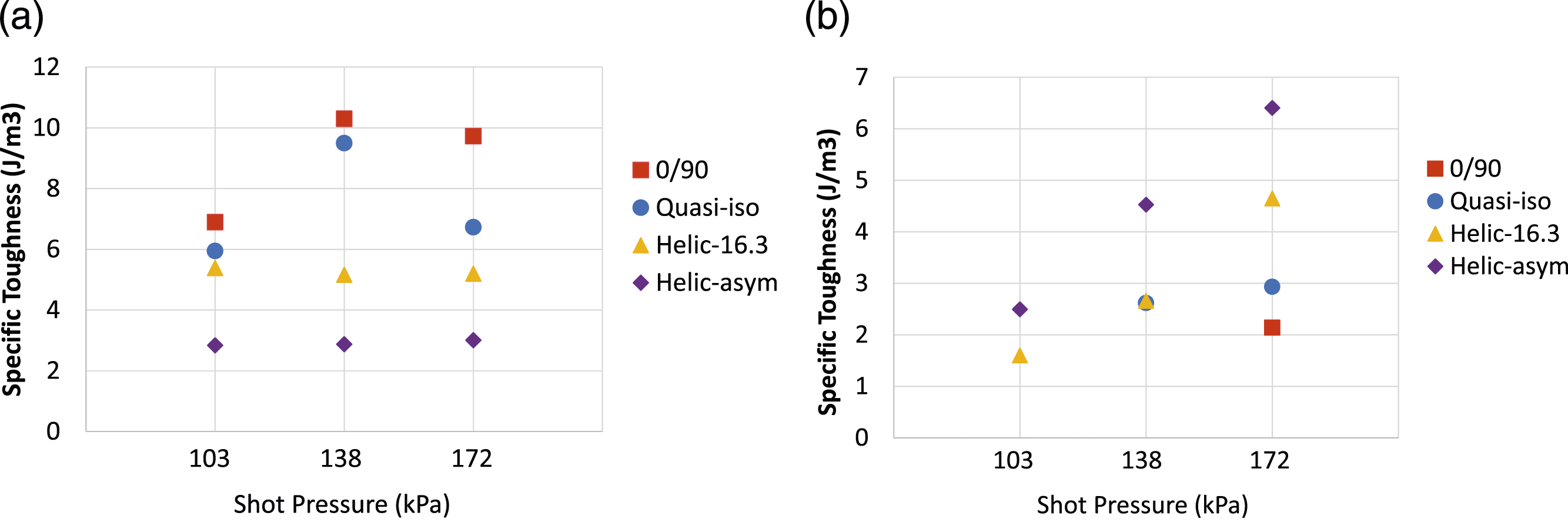
Conclusions
Bio-inspired helicoidal composites were successfully developed by compression molding of continuous glass fiber reinforced polypropylene composite preforms. Various tests ranging from quasi-static to high strain rate tests were performed to evaluate the properties of the helicoidal structure and their performance was compared to the conventional composites with cross-ply and quasi-static layup sequences. Some of the findings are listed below: • The helicoidal thermoplastic composite did not show advantages in the performance in the quasi-static test such as flexural testing or compression after impact or low strain rate tests such as Izod impact test or compression after impact test. • The helicoidal composites showed twisting fracture pattern for deflecting cracks involving more areas for energy absorption in addition to common failure mechanisms including delamination between composite layers, fiber fracture, and matrix fracture in the Izod impact test. • The high strain rate testing results showed that the bio-inspired helicoidal thermoplastic composite possessed both lower stress and larger strain during the test. The lower stress and larger strain for energy dissipation in the helicoidal composites tested at a high strain rate were favorable for damage mitigation. • The helicoidal composite had considerably higher toughness after peak stress than composite with conventional layup sequences in the high strain rate test, which can result in a better load-carrying capability of the helicoidal composite after the peak stress than the conventional composites. • Comparison of the damage on different thermoplastic composite samples after the high strain rate test indicated that the bio-inspired helicoidal thermoplastic composites had considerably better damage tolerance than conventional thermoplastic composites.
Footnotes
Declaration of conflicting interests
The author(s) declared no potential conflicts of interest with respect to the research, authorship, and/or publication of this article.
Funding
The author(s) disclosed receipt of the following financial support for the research, authorship, and/or publication of this article: Funding from the Air Force Research Laboratory Summer Faculty Fellowship Program is greatly appreciated.