
Abstract
The compatibility among nonpolar thermoplastics like polypropylene (PP) and carbon fibers (CF) having traditional sizing or coating is challenging. In this study, facile and effective surface functionalization of CF and its subsequent coating with functionalized carbon nanotubes (CNTs) were carried out to obtain improved interfacial shear strength (IFSS) which was validated by the single fiber fragmentation test (SFFT). Functional groups, -COOH, -OH, and -NH2, were separately grafted on the CF surface using different chemical routes. Additionally, ultrasonic assisted electrophoretic deposition (EPD) technique was used to coat -COOH, -OH, and -NH2 functionalized CNTs on the sized and surface functionalized CFs. Attenuated total reflection-infrared spectroscopy (ATR-IR), X-ray photoelectron spectroscopy (XPS), and field emission scanning electron microscopy (FE-SEM) images confirmed the successful surface functionalization and coating on CF. Neat PP and a blend of PP and maleic anhydride-grafted-styrene ethylene butylene styrene (MA-g-SEBS) were used as two different base polymer matrixes in preparing a total of 26 different SFFT samples. Silane functionalized CF coated with amine functionalized CNTs using ultrasonic assisted EPD process showed IFSS of ∼29 MPa which was an impressive ∼758% higher than pristine CF and highest among all the surface modified CFs. Interestingly, this translated into useful increase of ∼13% in single fiber tensile strength of functionalized and treated CF over and above that of as received CF.
Keywords
Introduction
Carbon fiber-reinforced polymer (CFRP) is a special class of material due to its significant strength-to-weight ratio and provides enormous benefit over traditional materials like steel and aluminium in making products requiring strength. 1 Applications of lightweight structural parts and components produced using CFRP are significantly demanding in automotive and aerospace industries. Thermoset polymers, as base resin, are mostly used and preferred for CFRPs as the combination provides excellent bulk mechanical properties.1–3 However, the use of thermoset resins like epoxy brings an issue for recyclability of CFs due to the presence of 3-dimensional cross-linked molecular structures in the cured CFRPs. With increasing environmental awareness, there has been increased focus on the application of thermoplastics, which have feasible recyclability and processability. Within thermoplastics, a commodity polymer like PP is chemically inert, dimensionally stable, cheap, and has very low density, which makes it a favourable candidate for use as a base matrix in lightweight fiber-reinforced composites.4,5 Although research pertaining to the use of CF as a reinforcement in PP matrix have been carried out extensively in the past, very few focussed on enhancing the interfacial adhesion among CF and PP. Fiber-matrix interphase plays a crucial role in determining the load carrying capacity of a composite material. Hence, surface modifications of CF by chemical or physical treatment are often done to create a strong interphase with base polymer matrix. 1 In the past, various studies have been dedicated to an improvement in interfacial adhesion among surface modified CF and different polymer matrices quantified by the enhanced interfacial shear strength (IFSS) of the composites.6–10
Liu et al. 4 functionalized CF with polydopamine layer using a facile dip coating method. An increase in IFSS to 18.62 MPa (up by ∼284%) was observed for the functionalized CF with combined PP and maleic anhydride-grafted-PP (MA-g-PP) as the base matrix compared to raw CF in PP. The occurrence of ring-opening reaction among the amine and catechol groups of polydopamine present on CF surface with the MA-g-PP of base matrix and the presence of hydrogen bonding was considered to be the primary reasons for this enhancement in IFSS. Chen et al. measured IFSS for CF/PP as a function of temperature using the fiber pull-out test method. An embedded length of 85 microns and MA-g-PP was blended into the PP to promote adhesion. IFSS of 34.9 MPa was measured at room temperature with evidence of cohesive failure in the resin versus interfacial failure. 11 Luo et al. 12 used a layer-by-layer technique to coat graphene oxide (GO) and polyethyleneimine (PEI) on CF surface. Microbond test using PP were carried out for the GO-PEI coated CF, and it was observed that for an optimal bilayer number of 10 the IFSS almost doubled from 4.8 MPa (for pristine CF and PP) to 10 MPa. The improvement in interfacial adhesion, and hence, in IFSS was due to the acidification and coating of the CF which increased the surface roughness of the fibers. Yamaguchi et al. 5 investigated the effect of telechelic PP on the interfacial adhesion with CF. It was observed from the microdroplet tests that hydroxyl terminated PP displayed an IFSS of 17.7 MPa with commercially sized CF whereas it increased to ∼22 MPa when the CF sizing was removed. The role of hydrogen bonding among the CF and PP was believed to be the contributing factor. Zhu et al. 7 coated CF with polyetherimide nanoparticles and found only ∼50% improvement in IFSS whereas, significant improvement in interfacial adhesion was observed for other thermoplastic resins like polyamide-6 and polyamide-66. CF was coated with ethylene–methyl acrylate–glycidyl methacrylate terpolymer through a solution dipping by Liu et al. 13 and an increase in IFSS by ∼157% was observed in comparison to pristine CF in PP. Arao et al. 14 observed a significant improvement in IFSS by ∼214, ∼203, and ∼186% respectively for CF reinforced in different PP matrix, each filled separately with 1 wt.% nanofiller of silica, alumina, and CNT. CF surface modification carried out by Servinis et al. 6 with amine and carboxylic as pendant groups displayed an IFSS of ∼25 and ∼12 MPa respectively in a MA-g-PP matrix.
To the best of authors knowledge, a comprehensive and systematic study on the effect of various surface modified CF on its IFSS with PP and its blends have not been reported earlier. In the present study, facile surface functionalization of CF has been carried out to graft -OH, -COOH, and -NH2 groups. In addition, ultrasonic assisted EPD process was adopted to coat -COOH, -OH, and -NH2 functionalized CNT on sized and surface functionalized CF. The effect of the presence of the functional groups and CNT coating on the variation of IFSS has been evaluated by SFFT separately for neat PP matrix and blend of PP and MA-g-SEBS. A total of 26 different samples were prepared for studying the IFSS. The characterization of interfacial properties and associated understanding of interfacial behaviour from this study will help to develop new and/or better sizing material for CF that shall exhibit excellent interfacial adhesion and mechanical properties when used with thermoplastics like PP and its blends.
Materials and methods
Material
Continuous CF having a specification of TC33-3K, with 3,000 fibers per tow was bought from Jalark Carbon products, India. PP and MA-g-SEBS were purchased by Reliance India Limited (RIL), India, and DZBH New Material, China respectively. The silane coupling agent (3-Aminopropyl) triethoxysilane (APTES) was procured by Sigma Aldrich. The -OH and -COOH functionalized CNTs and all the chemicals for reactions were also bought from Sigma Aldrich.
Surface functionalization and EPD process
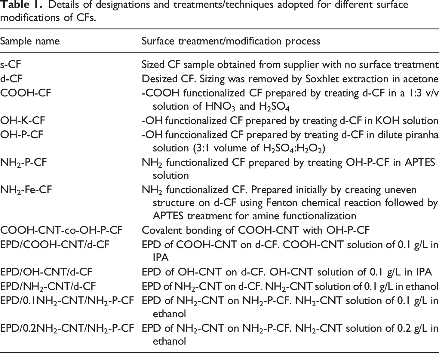
Details of designations and treatments/techniques adopted for different surface modifications of CFs.
For the amine functionalization of CNT, initially dried COOH-CNT obtained from the supplier was reacted with 100 mL thionyl chloride (SOCl2) and 5 mL DMF solution at 70°C for 48 h to yield acyl chloride functionalized CNT (COCl-CNT).20,21 To subsequently introduce -NH2 groups, the obtained COCl-CNT was functionalized by aromatic diamine. To do this COCl-CNT was dispersed in 80 mL of dichloro methane (CH2Cl2) containing 5 g aromatic diamine of 4.4′-diamino diphenyl methane (DDM). After that, the resulting mixture was sonicated for 15 min and next refluxed for 24 h at 90°C. NH2-CNT were thus prepared through an amide linkage. The mixture solution was then washed in acetone and separated NH2-CNT kept for drying at 60°C for 24 h.
Covalent grafting of COOH-CNT on OH-P-CF was carried out by dropwise addition of COOH-CNT solution on to OH-P-CF surface. 10 Initially, COOH-CNT was added to DMF to make a 0.1 g/L solution by sonicating it for 40 min. The solution was then heated for 30 min at 70°C. In a separate beaker, OH-P-CF was taken and a few drops of H2SO4 were added. The heated COOH-CNT solution was added to the beaker containing OH-P-CF and was refluxed for 30 min at 70°C. The prepared COOH-CNT-co-OH-P-CF was filtered and dried overnight. The grafting reaction was confirmed by the presence of ester linkage using ATR-IR and XPS.
The EPD process was carried out at 30 V and 0.02 mA to deposit different functionalised CNTs on CF surface. The samples prepared are listed in Table 1. To prepare the CNT dispersed solutions, isopropyl alcohol (IPA) and ethanol were used as solvent. Prior to use, the respective CNT solutions were sonicated for at least 2 h for proper dispersion of CNTs. An aluminium tube of diameter ∼1.5 cm was used as a counter electrode to confirm uniform CNT coating along the circumference of CF. The EPD process was assisted by ultrasonication so as to obtain a uniform and continuous dispersion of CNTs in the solution during the coating. The selection of cathode and anode in the EPD process was based on the type of surface charge the functionalized CNTs exhibit. For instance, NH2 functionalized CNT (NH2-CNT) carries a positive charge,22,23 and hence, during the EPD process the CF to be coated was connected to a negative terminal and acted as a cathode. Similarly, the -OH and -COOH functionalized CNTs (namely OH-CNT and COOH-CNT) carry a negative charge, and therefore, in this case, the CF was connected to a positive terminal and acted as anode.22,23 The schematic representation of the adopted EPD process for the surface modification of CF is illustrated in Figure 1. Schematic representation of the ultrasonic assisted EPD process for the surface modification of CF. The anode and cathode were chosen based on the type of charge the CNTs carry. Post the EPD process, only the dipped portion of CF that underwent coating was used for the analysis after drying.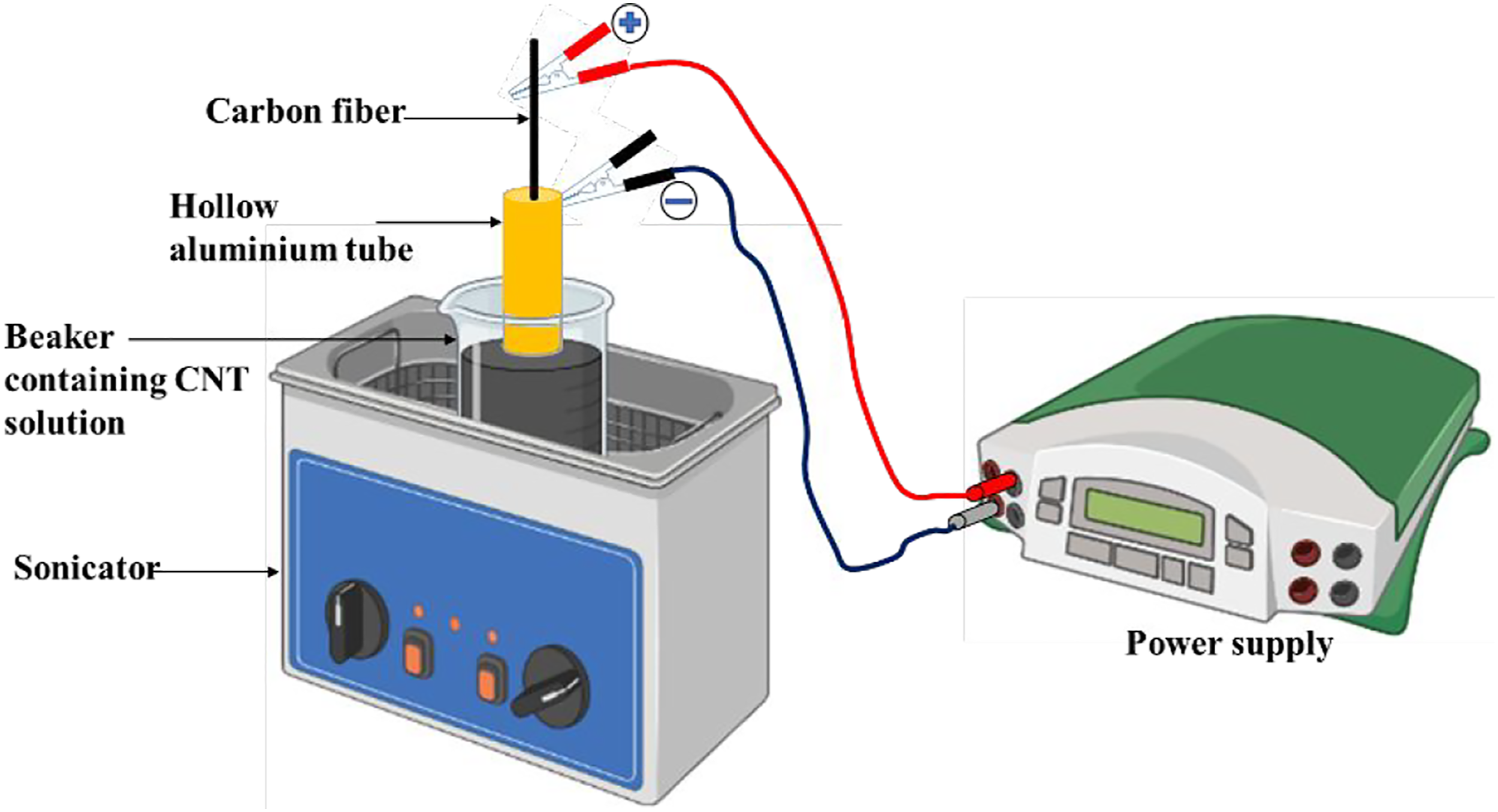
Attenuated total reflection-infrared spectroscopy (ATR-IR)
The surface functionalization carried out in this study was verified by ATR-IR analysis of each sample in L1600400 Spectrum TWO DTGS, UK onto the surface of the Zinc Selenide (ZnSe) at room temperature. Samples were oven-dried prior to testing.
X-ray Photoelectron Spectroscopy (XPS)
The X-ray Photoelectron Spectroscopy (XPS) was carried out in PHI 5000 VersaProbe III (Make: Physical Electronics). Fine scan spectra of O1s, C1s, and N1s were obtained and analysed to confirm the desired surface modification of CFs.
Morphology SEM
The morphological analysis of the sized, desized, and surface functionalized carbon fibers was done using a scanning electron microscope, MIRA 3 LM (FE-SEM) (Make: TESCAN). Sputter coating of the entire fiber surface was done prior to the analysis using gold-palladium alloy.
Fiber tensile test
Tensile test of the sized, desized and the surface functionalized CFs were carried out in an Instron UTM following ASTM C1557 test protocol. The test was performed at the rate of 0.2 mm/min and the gauge length was fixed at 20 mm. At least 20 samples of each specimen were tested and the average tensile strength,
Sample preparation and IFSS calculation
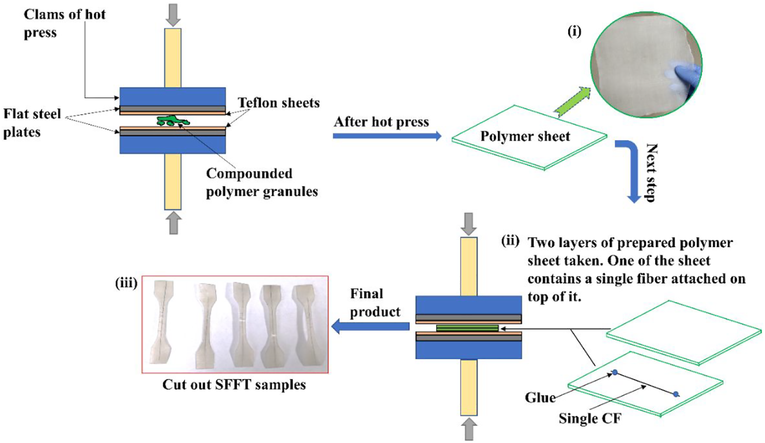
For evaluating the IFSS, dog-bone shaped tensile specimens were prepared for the single fiber fragmentation test (SFFT) having dimensions as shown in Figure 2. To prepare the samples, two sheets of desired polymer matrix of thickness ∼0.30 mm was taken, and a single CF was placed in between them a single CF was placed with utmost care. This system was compressed in a hydraulic press at a temperature of ∼290°C for PP and its blend. The systematic method of preparation of SFFT samples has been illustrated in Figure 3. Schematic of a single fiber fragmentation test specimen. Preparation of SFFT sample represented by: (i) initially thin sheets of PP or its blend with MA-g-SEBS were prepared using a hot press. It followed by attachment of a single CF on top of a sheet using glue and then, (ii) hot compressing it by placing another sheet over it, (iii) SFFT dog bone samples were cut out from the compressed sheet by keeping the fiber at the centre with specific dimensions.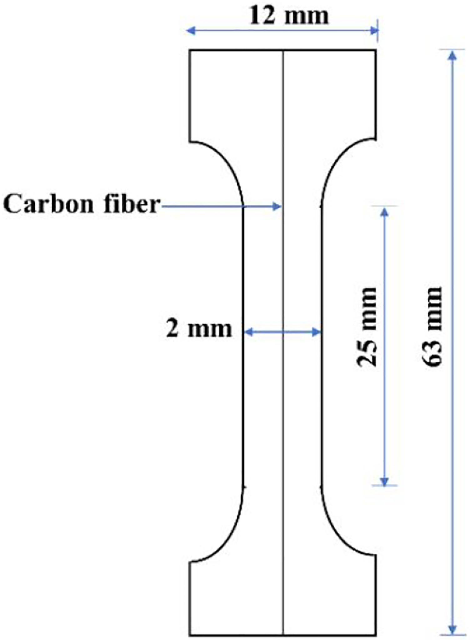
The prepared SFFT samples were loaded in a UTM and subjected to an extension loading rate of 0.05 mm/min. The samples were elongated for a time duration of 60 min to have a complete fragmentation of the single carbon fiber embedded by the matrix. After the loading the SFFT samples were observed under an optical microscope and the respective length of all the fiber fragments was noted down.
The SFFT works on the principle that under an applied elongation load, initially the stress is transferred from the matrix to the fiber. As the load increases, the stress in the fiber-matrix interfacial region also increases and reaches a level which exceeds the inherent tensile strength of the fiber and the fiber fragments. With further increase in the load, the number of fiber fragments increases and reach a point at which the interphase can no longer attain the required ultimate fracture strength of the fiber. A strong interphase requires small area for the transfer of same load compared to a weak interphase, and hence, the former creates numerous fragments compared to the latter.
The IFSS, τ was calculated using equation (1) in which l
c
is the critical fiber fragmentation length when the fiber breaks.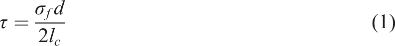
Results and discussion
ATR-IR
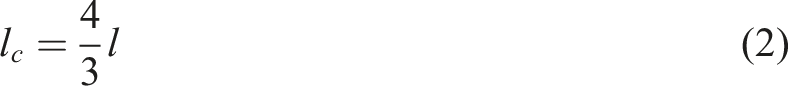
The confirmation of successful surface modifications of CF with different functional groups was carried out by performing an exhaustive ATR-IR analysis. The ATR-IR scan of s-CF, d-CF, and COOH-CF can be seen in Figure 4(a). No prominent peaks were observed for the s-CF and d-CF, due to high concentration of carbon.
24
However, stretching vibration of C–H of methyl and methylene groups in the range of 2800–2980 cm−1 for s-CF, and C = C stretching vibration centred around 1668 cm−1, were observed for the s-CF
25
and d-CF. The feeble peak at 3671 cm−1 and around 1020 cm−1 are attributed to the O-H groups on the surface due to ambient atmospheric moisture for both s-CF and d-CF. The confirmation of the desizing of CF is later explained in the XPS analysis in Section 3.2. Furthermore, COOH-CF showed a broad peak at 3424 cm−1, which is assigned to the stretching vibration of O-H groups. Two new peaks appeared at 1215 and 1760 cm−1 correspond to the stretching vibration of C–O and C = O of -COOH group, respectively. The ATR-IR peaks of -OH functionalized CF using KOH and piranha solution is shown in Figure 4(b). For OH-K-CF broad peak at 3430 cm−1 represents O-H stretching, while peaks at 1635 and 1080 cm−1 represents the C = C and C-O stretching, respectively. For OH-P-CF, O-H stretching can be seen as a broad peak at around 3383 and 2987 cm−1. Peak at 1132 cm−1 represent C-O stretching while peak at 1425 cm−1 represents O-H bending. The absorption peak at 1705 and 878 cm−1 depicts the C = O stretching and C-H bending. It is important to note here that oxidation of CF using reagents like piranha solution may create a number of oxygen containing groups at the fiber surface such as -OH, -COOH, and C = O.16,26 The quantification of the same has been carried out and discussed in the XPS analysis Section 3.2. The amine functionalization of CF was carried out using two routes as earlier mentioned in Table 1, was confirmed by the ATR-IR peaks as shown in Figure 4(c). For the NH2-P-CF peaks at 1132, 1625, and 3346 cm−1 represents the C-N stretching, N-H bending, and N-H stretching of the amine group respectively, whereas the same was observed for NH2-Fe-CF at 1234, 1615, and 3599 cm−1 respectively. Furthermore, the peak at 2924 and 2856, 1464, and 1250 cm−1 of the NH2-P-CF represents the C-H stretching, C-H bending, and C-N stretching respectively. The C = O stretching and C = C bending of NH2-Fe-CF was observed at 1764 and 991 cm−1 respectively. Illustrations of ATR-IR plots of (a) s-CF, d-CF, and COOH-CF, (b) OH-K-CF and OH-P-CF, (c) NH2-P-CF and NH2-Fe-CF, (d) COOH-CNT-co-OH-P-CF, (e) COOH-CNT, NH2-CNT, and OH-CNT.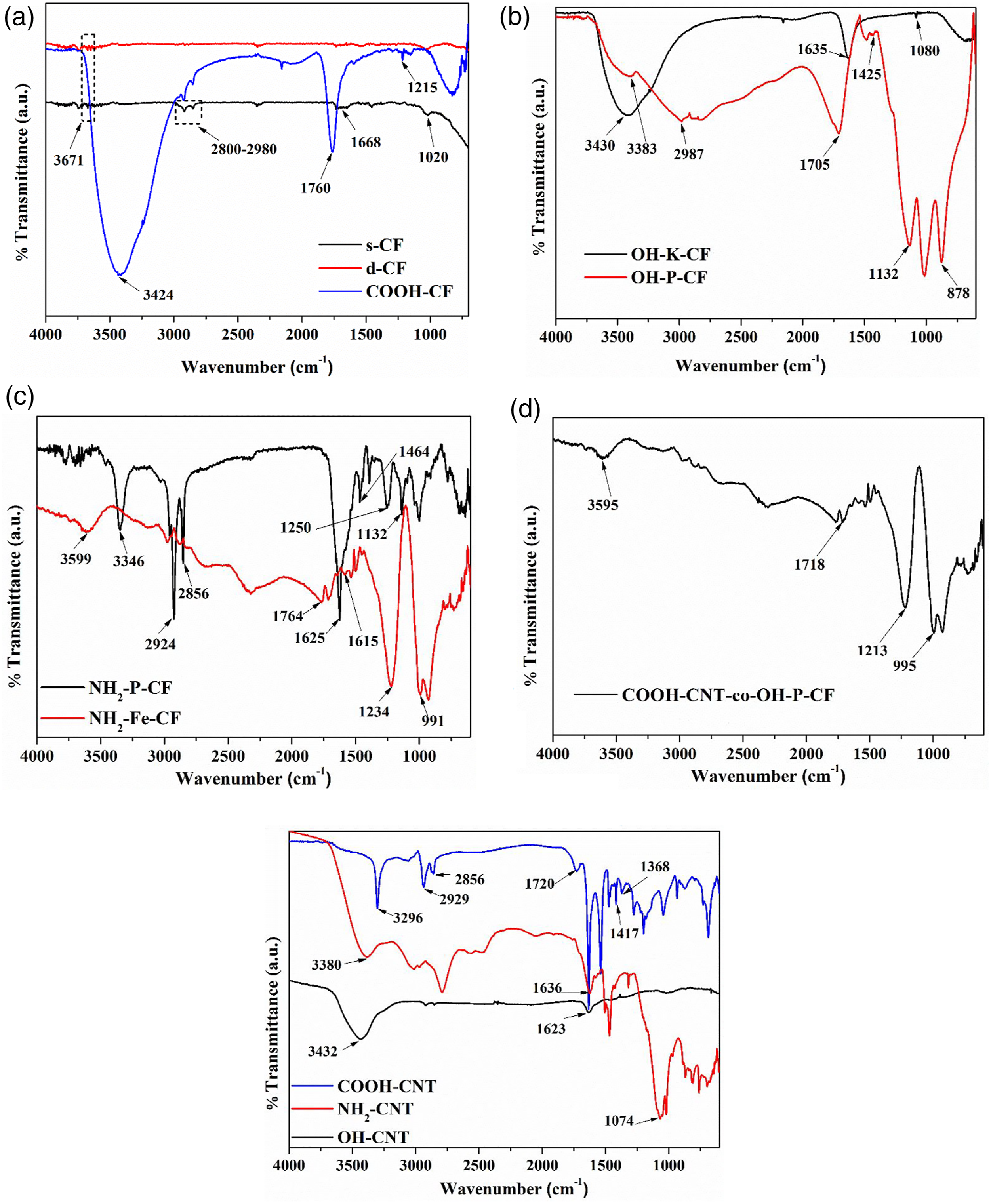
The successful grafting of COOH-CNT on OH-P-CF was confirmed by the presence of ester linkage in the ATR-IR plot, as shown in Figure 4(d). The peak at 1718 cm−1 represents the C = O stretching while 1213 cm−1 peak represent the C-O stretching of the ester linkage. Further, the peak at 3595 cm−1 presents the O-H stretching of the hydroxyl groups present on the surface of OH-P-CF. Another peak at 995 cm−1 represents the C = C bending of the fiber.
The ATR-IR plot of the functionalized CNTs used for the u-EPD process are shown in Figure 4(e). The COOH-CNT shows O-H bending of -COOH at 1368 and 1417 cm−1, and C = O and O-H stretching at 1720 and 3296 cm−1, respectively. The peaks at 2929 and 2856 cm−1 are assigned to the C-H stretching vibrations produced at the defect sites. 27 The ATR-IR spectra of CNT-NH2 presents a C–N stretching band at around 1074 cm−1, indicating that amine groups were introduced on the CNT surface. Furthermore, the N-H stretching and the N–H deformation bonds of the primary amine groups appear at 3380 cm−1 and 1636 cm−1, respectively. Thus, the formation of amine terminated CNT was confirmed. Furthermore, for the OH-CNT the O-H and C = C stretching occurred at 3432 and 1623 cm−1 as can be observed in Figure 4(e).
XPS
The presence of different elements on the surface of CF induced by the modification processes was confirmed and validated by XPS. The wide scan XPS spectra of all the CF is illustrated in Figure 5. Peaks around ∼285, ∼532, and ∼400 eV correspond to the C1s, O1s, and N1s. The relative atomic percentage of elements for all the CF samples along with their O/C and N/C ratio are listed in Table 2. It can be observed in Table 2 for s-CF and d-CF that the desizing of the CF can be related to the decrease in O1s content from 22.84 to 15.83%. Considerable removal of the epoxy sizing containing oxygen groups may be a probable reason for this change. The oxygen content further increased with surface modification process that were aimed to incorporate -COOH and -OH groups on CF as evident for COOH-CF, OH-K-CF, and OH-P-CF. The O/C ratio in Table 2 also infers a higher ratio for OH-P-CF than OH-K-CF. In case of the amine functionalized CFs, an apparent increase in the nitrogen content to 7.45 and 6.62% was observed for the case of NH2-P-CF and NH2-Fe-CF, respectively. The N/C ratio was observed to be relatively higher for NH2-P-CF (0.11) compared to the NH2-Fe-CF (0.8). Wide scan XPS spectra of all the different surface modified CFs (a) using different chemical routes and (b) using ultrasonic assisted EPD process. Relative atomic percentage (%) of elements.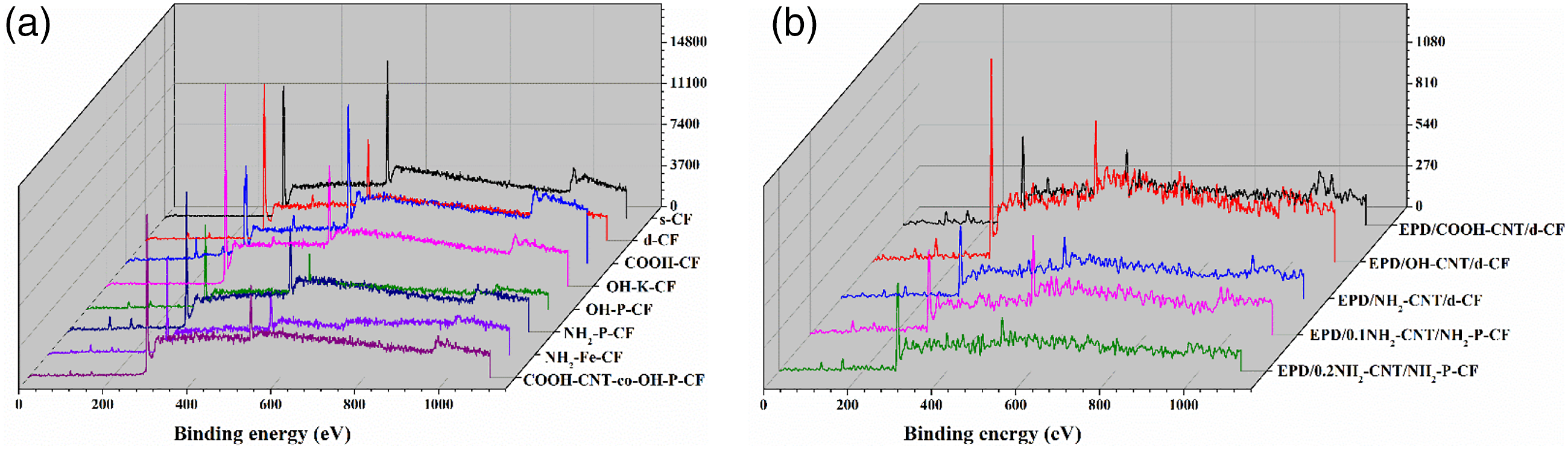
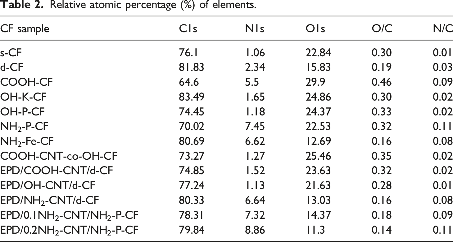
For the covalently grafted COOH-CNT on OH-P-CF, the oxygen content increased with a O/C ratio of 0.35. For the CNT coated CF using EPD process, the relative atomic percentage was based on the type of functionalized CNT. The O/C ratio was highest for EPD/COOH-CNT/d-CF whereas the N/C ratio was highest for EPD/0.2NH2-CNT/NH2-P-CF.
More detailed information about the chemical transformations occurring on the carbon fibre surface was obtained by analysing the deconvoluted high resolution spectra of C 1s (Figure 6) and O 1s (Figure 7). The area proportions of the constituent peaks along with the corresponding binding energies have been summarized in Table 3 and Table 4 for C 1s and O 1s respectively. After the desizing treatment with acetone, the percentage of the component peak at 286.6 eV corresponding to C-O-C = O or epoxide as seen in Figure 6(a) and (b) considerably reduced from 22.32% to 3.63% as listed in Table 3. Also, in the O 1s curves, the relative peak area representing singly bonded oxygen, which can possibly be due to the hydroxyl bonds or C-O-C, has decreased from 56.85 to 15.61%. This suggests the successful removal of the epoxy sizing from the fibre surface. In the following discussion, chemical changes due to all other surface treatments (except COOH-CNT-co-OH-P-CF) were assessed with C 1s and O 1s XPS spectra of the d-CF as reference. C1s spectra of (a) s-CF, (b) d-CF, (c) COOH-CF, (d) OH-K-CF, (e) OH-P-CF, (f) NH2-P-CF, (g) NH2-Fe-CF, and (h) COOH-CNT-co-OH-P-CF. O1s spectra of (a) s-CF, (b) d-CF, (c) COOH-CF, (d) OH-K-CF, (e) OH-P-CF, (f) NH2-P-CF, (g) NH2-Fe-CF, and (h) COOH-CNT-co-OH-P-CF. Area proportion (%) of respective peaks obtained from the C1s spectra in XPS analysis for different CF samples. Area proportion of respective peaks obtained from the O1s spectra in XPS analysis of the different CF samples.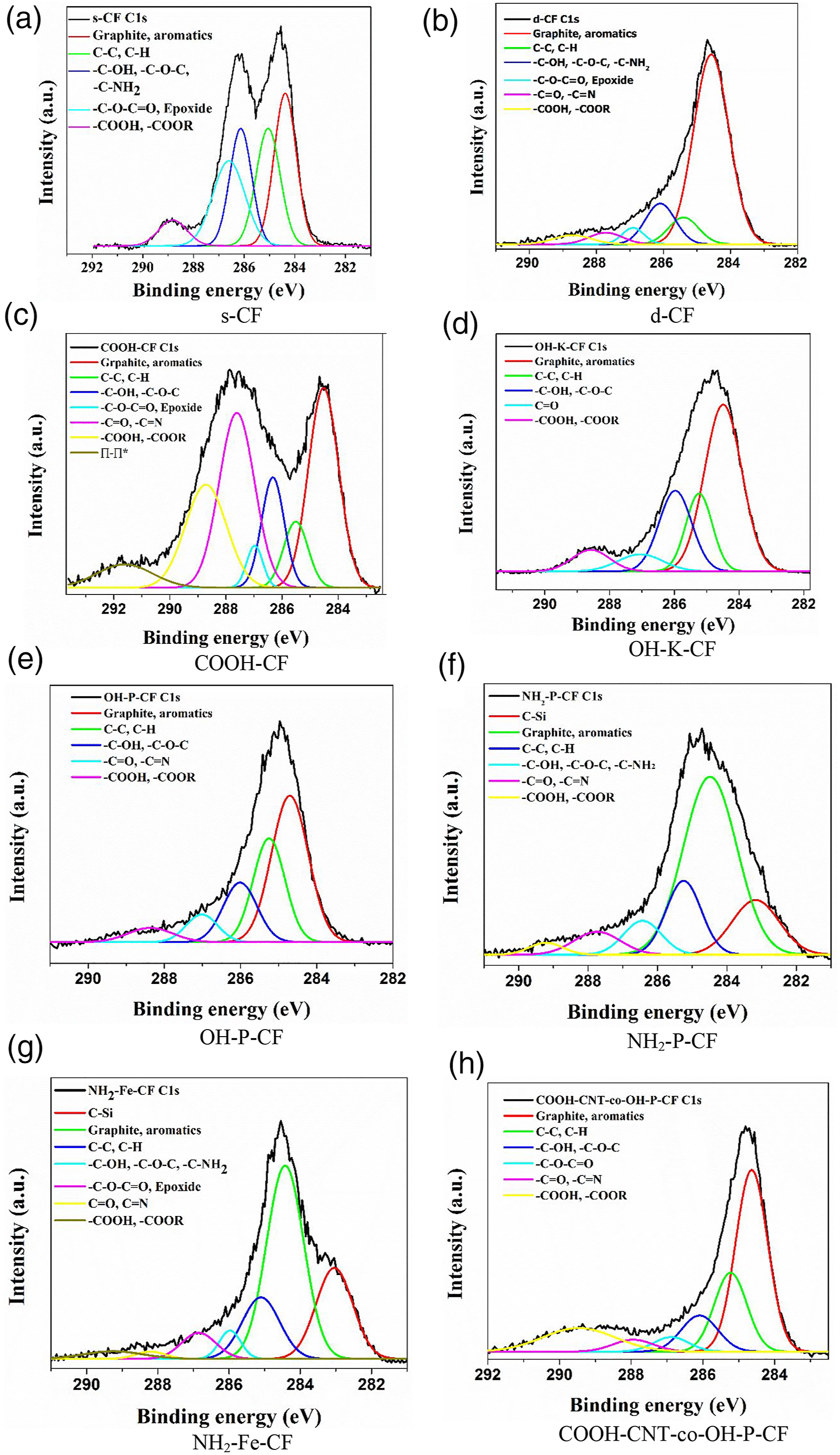
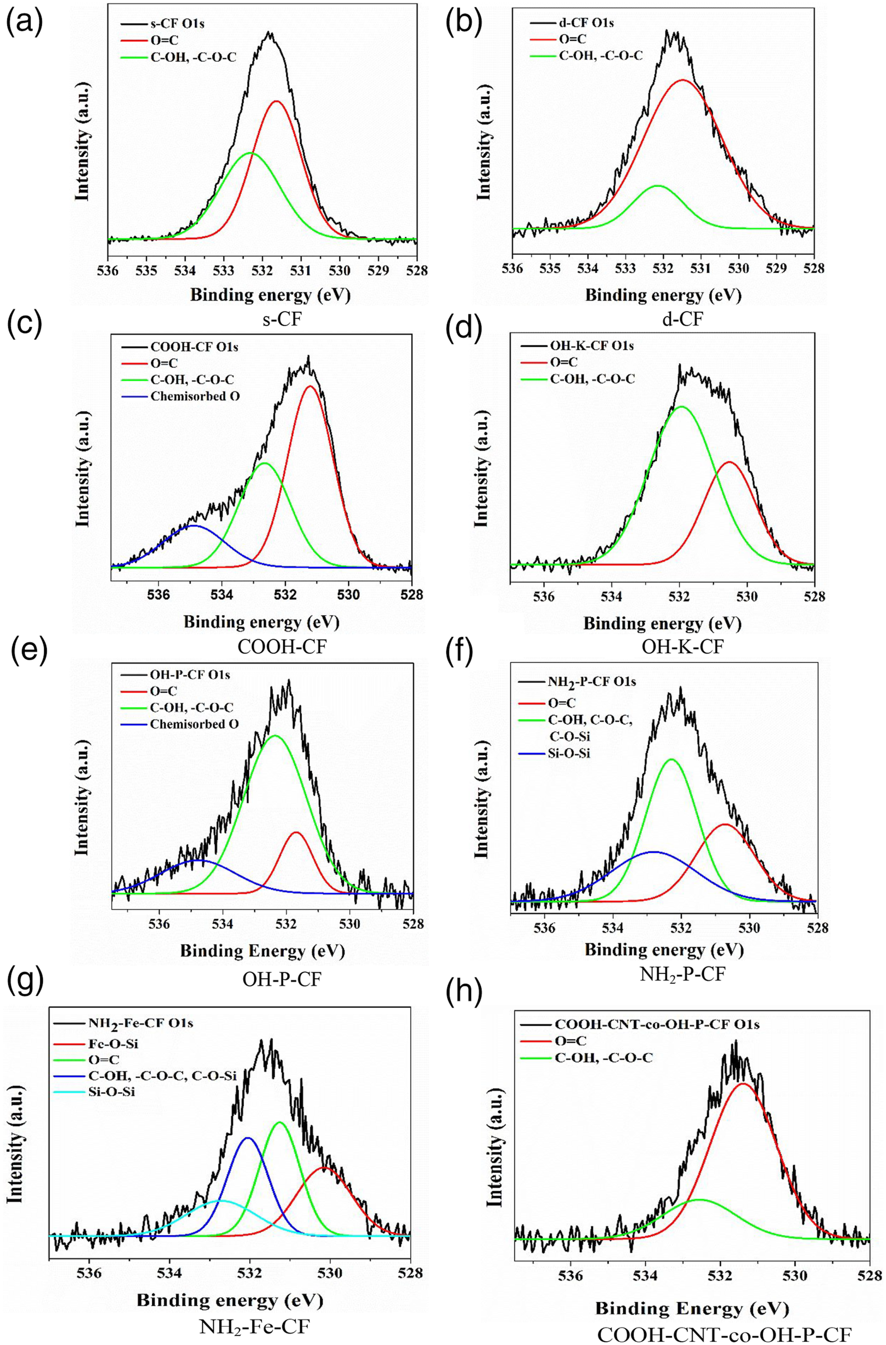
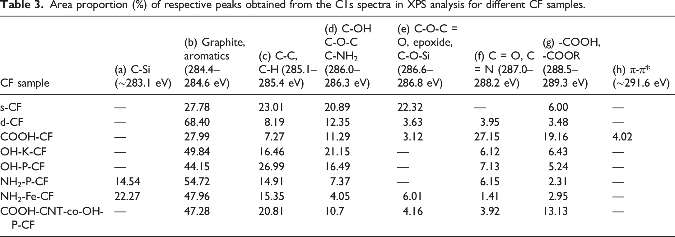
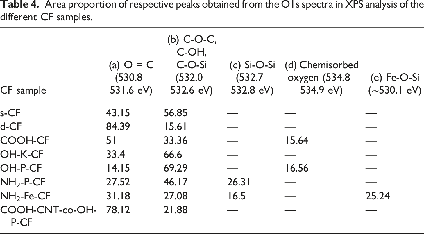
It is evident from the C 1s spectra of sample COOH-CF in Figure 6(c) that the total carbonyl content as well as carboxyl content has fairly increased as a result of the acidic oxidation. Further, there is an additional peak at 534.9 eV in the O 1s spectra of COOH-CF in Figure 7(c) which can be attributed to chemisorbed oxygen. It can be deduced from C 1s spectra of OH-K-CF in Figure 6(d) and O 1s spectra in Figure 6(d) that the reaction with KOH resulted in alteration in the relative amounts of surface functional groups of the d-CF. Particularly, the area ratio of the C-OH peak (binding energy 286 eV) increased from 12.35% to 21.15% as observed in Table 3. Similar effect was also observed in case of the piranha (H2SO4/H2O2) treatment where the total content of carbon with functional groups (which is the summation of area proportion presented in column (d), (f), and (g) of Table 3 for OH-K-CF and OH-P-CF) increased from 23.41% to 28.86%. This modification could have been brought about by the free oxygen radical generated by the following reaction:
From the deconvoluted O 1s spectra for OH-K-CF and OH-P-CF in Figure 7(d) and (e) it was observed that in both these cases the relative proportion of functional groups with singly bonded oxygen like C-OH or C-O-C was >60% as mentioned in Table 4.
The C 1s curves of the silanized sample NH2-P-CF and NH2-Fe-CF in Figure 6(f) and (g) contain an additional distinct peak around 283.1 eV representing the C-Si bond which confirms the grafting of APTES onto the d-CF. Further, O 1s spectra of NH2-Fe-CF in Figure 7(g) shows peaks for Fe-O-Si and Si-O-Si at 530.1 eV and 532.7 eV respectively.
The appearance of these peaks is due to the silanization followed by the Fenton reaction. XPS investigation cannot provide sufficient information to distinguish between an ester (-COOR) and a carboxylic acid (-COOH) group because of their closer binding energies. The formation of an ester linkage between COOH-CNT and OH-P-CF for COOH-CNT-co-OH-P-CF has already been validated by the ATR-IR data in Section 3.1. Therefore, an increase in –COOH or -COOR peak area from 5.24% for OH-P-CF to 13.13% for COOH-CNT-co-OH-P-CF as seen in column (g) of Table 3 and similarly an increase from 14.15% to 78.12% in the doubly bonded oxygen content in the O 1s spectra as mentioned in column (a) of Table 4 can be considered as corroboration of this finding ascertaining the covalent bonding between the two.
Morphological analysis
The surface morphology of the CF was analysed by FE-SEM and depicted in Figure 8. It can be observed from the SEM images that for s-CF, d-CF, COOH-CF, OH-K-CF, OH-P-CF, and NH2-CF there were no such prominent changes in the surface morphology, except for the fact that in comparison to s-CF the rest had no epoxy sizing. In contrast, the NH2-Fe-CF showed a visible rough surface morphology with protruded structures as shown in Figure 8(g). SEM images of (a) s-CF, (b) d-CF, (c) COOH-CF, (d) OH-K-CF, (e) OH-P-CF, (f) NH2-P-CF, (g) NH2-Fe-CF, (h) COOH-CNT-co-OH-CF, (i) EPD/COOH-CNT/d-CF, (j) EPD/OH-CNT/d-CF, (k) EPD/NH2-CNT/d-CF, (l) EPD/0.1NH2-CNT/NH2-P-CF, and (m) EPD/0.2NH2-CNT/NH2-P-CF. The inset image in (g) NH2-Fe-CF represnts the zoomed-in image of the rough topography of the fiber. The regions encircled with yellow dashed line in Figure (m) EPD/0.2NH2-CNT/NH2-P-CF represent CNT agglomerations.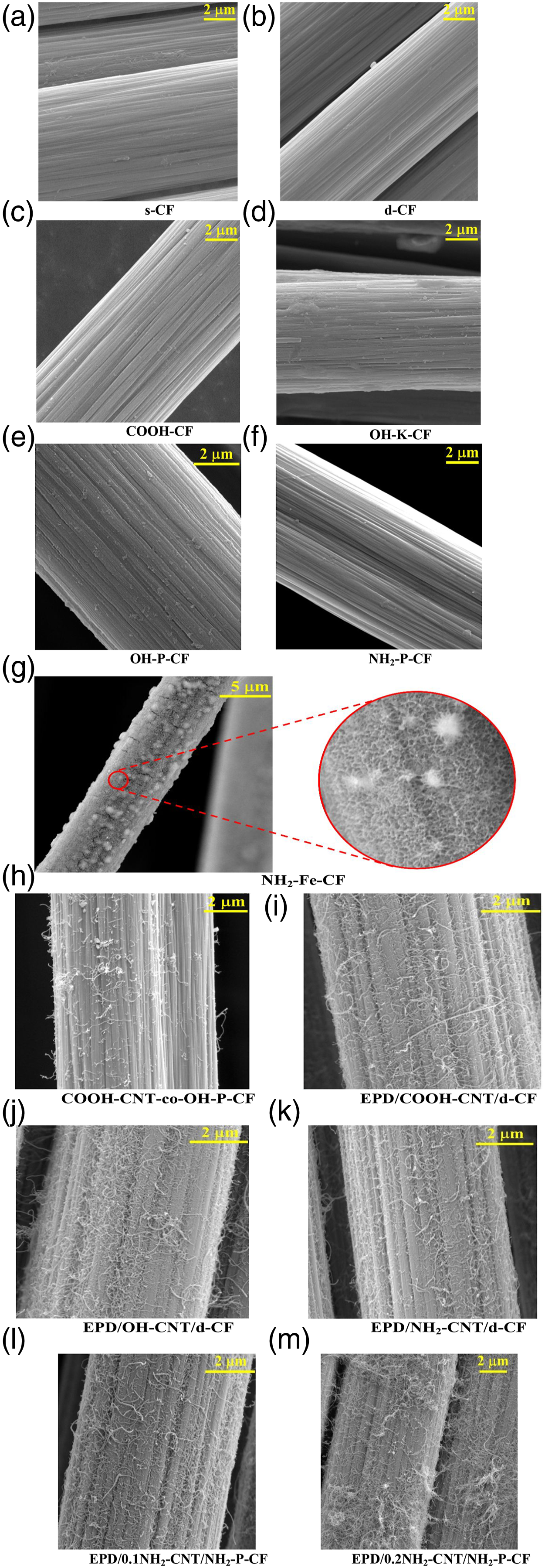
The rough topography was induced on the NH2-Fe-CF surface by the Fenton reaction which introduced OH radicals that attacked the fiber surface and formed defects that are desirable for improving interfacial adhesion. 19 In case of the COOH-CNT-co-OH-CF, the COOH-CNT which are covalently bonded to the surface of OH-CF can be quite visibly seen attached to the fiber surface in Figure 8(h). The grafting strength of such similar covalently bonded CNTs have been earlier demonstrated by Islam et al. 10 by pulling out a single CNT with the help of an atomic force microscope (AFM) tip. It was observed that the breakage of CNT during the pull-out rather than its detachment from the CF surface confirmed a strong bonding which was aided by the formation of covalent bond. In the present study, the formation of this covalent bond responsible for providing grafting strength has been confirmed by the presence of ester linkage as discussed previously in the ATR-IR and XPS analysis. Furthermore, the SEM images of the different CNT coated CFs using EPD process are illustrated in the Figure 8(i)–(m). The presence of a forest of different functionalized CNTs covering the surface of respective CF confirms the successful coating using the EPD technique and the parameters considered for the process. A dense and good dispersion of CNTs was observed for the CFs that employed 0.1 g/L concentration of CNT solution during the EPD process as quite apparent from the Figure 8(i)–(l). It is to be noted here that the EPD process was ultrasonically assisted, ensuring that the CNT solution considered for the process remained in a state of constant sonication for the entire duration of coating. This supported a relatively better dispersion of CNT along with a dense deposition on the CF surface, unlike previously obtained sparse distribution of CNT due to absence of ultrasonication. 28 On the other hand, in the case of EPD/0.2NH2-CNT/NH2-P-CF that used 0.2 g/L of CNT solution, the presence of CNT agglomeration can be clearly observed from the SEM image presented in Figure 8(m). The agglomeration plausibly resulted due to excess concentration of CNT in the solution. Nonetheless, in the present study 0.1 g/L CNT solution has demonstrated a satisfying outcome. Furthermore, during the EPD process considering CF as anode for EPD/COOH-CNT/d-CF, and EPD/OH-CNT/d-CF as cathode for EPD/NH2-CNT/d-CF, EPD/0.1NH2-CNT/NH2-P-CF, and EPD/0.2NH2-CNT/NH2-P-CF, was logical for the coating of CF with different functionalized CNTs carrying either positive or negative charge.
Single fiber tensile test
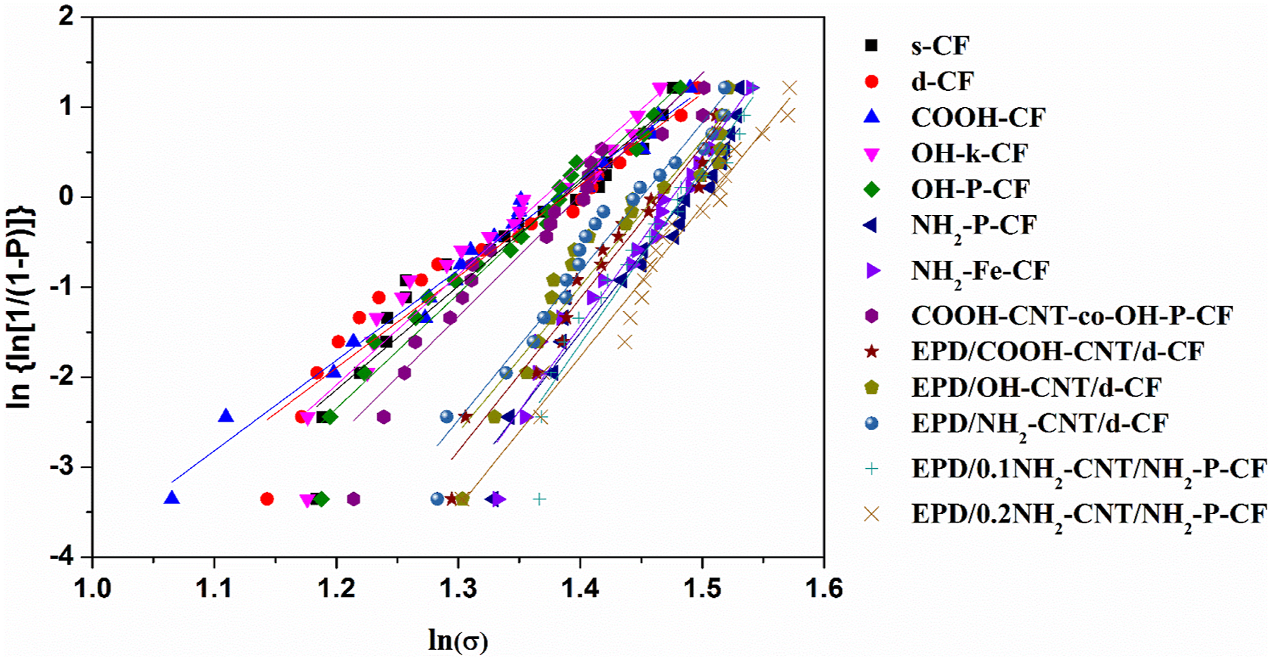
The single fiber tensile strength tests were carried out according to ASTM C1557 to observe any changes in the inherent fiber tensile strength brought in by the different surface modification processes. The tensile strength of engineering fibers like CF cannot be described entirely using a single value, and hence, in the present study, Weibull distribution was used.29–32 The two parameters Weibull distribution is given by equation (4).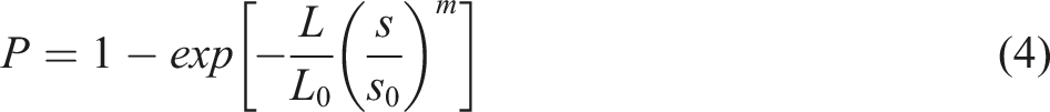

Using equation (6) and plotting the respective values for the CFs, the Weibull distribution for different CF studied here. The linear fitting for each set of data provided an R2 > 0.9 ensuring good fit. The model parameter estimates, m and σ
0
, from the plot are listed in Table 5. Tensile strength of different CF along with the Weibull distribution parameters, m and σ
0
.
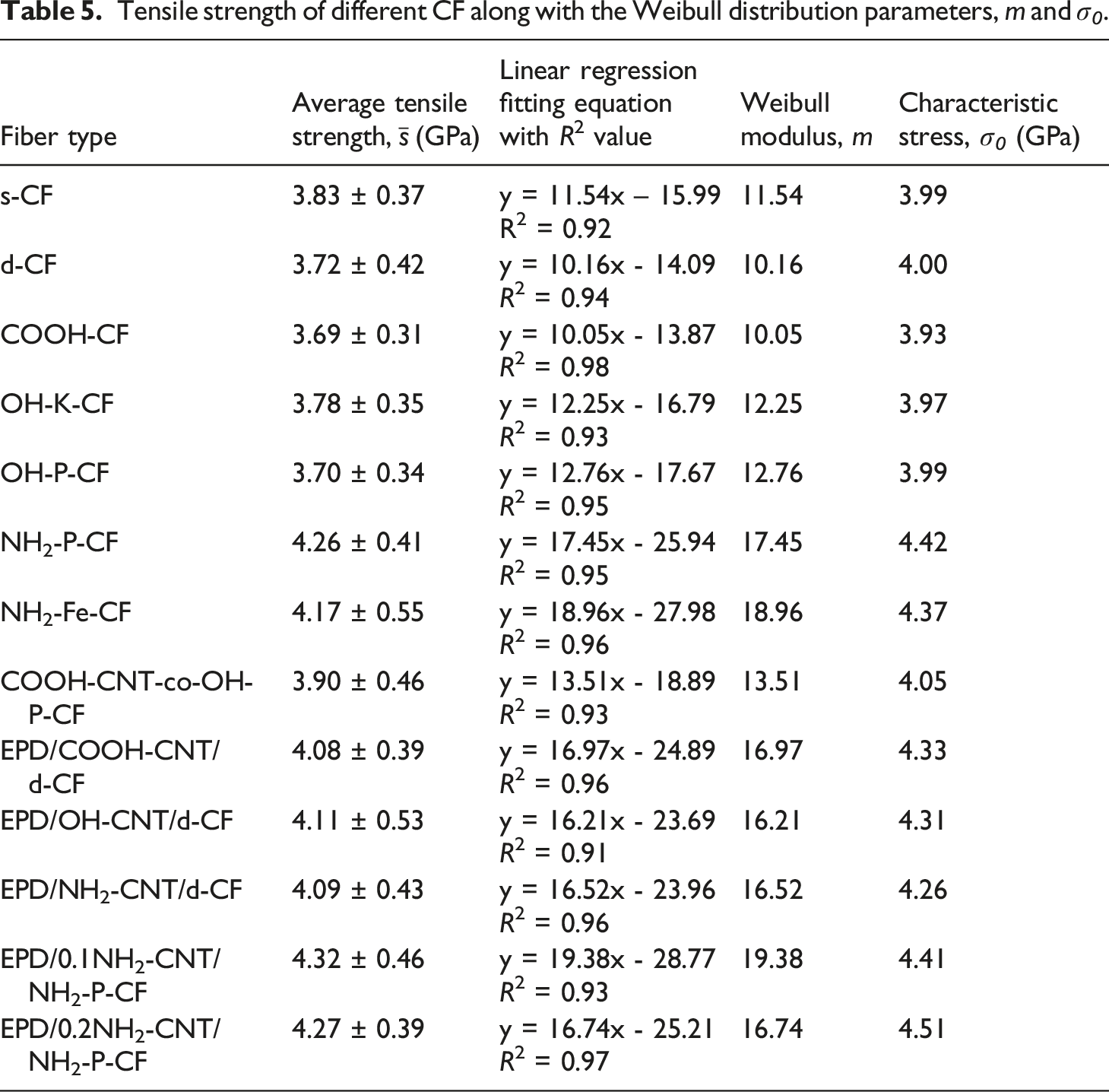
The average tensile strength,
Moreover, comparing the Weibull modulus,
IFSS
Obtained IFSS values for surface modified CF with PP and PP blend.
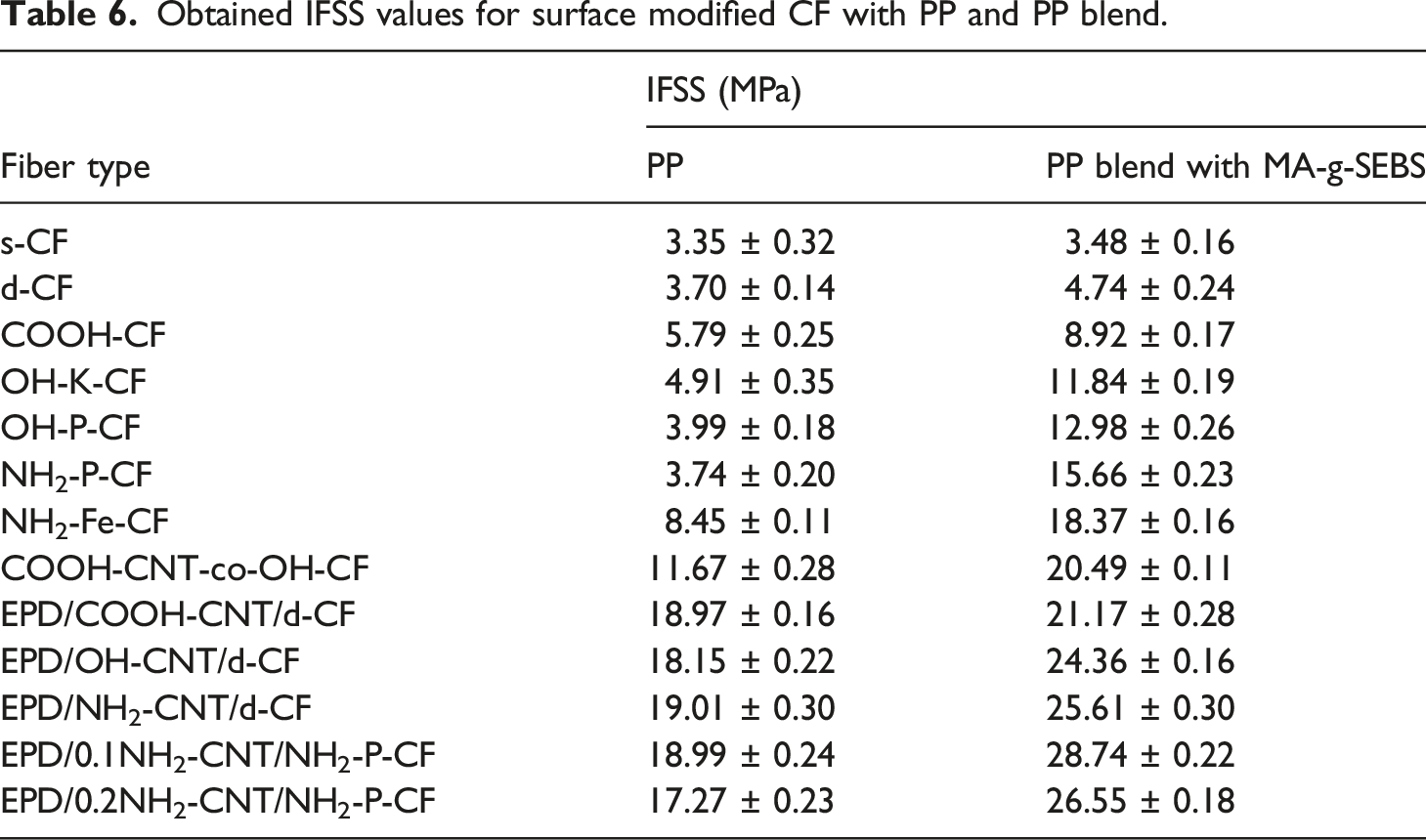
It can be observed that s-CF with low affinity towards non-polar PP demonstrated a low IFSS value of 3.35 ± 0.32 MPa while for the PP blend it increased slightly to 3.48 ± 0.16 MPa. A similar observation of low IFSS was earlier reported by Zhu et al. 7 for PP/CF. Upon desizing the CF, the IFSS increased slightly which may have occurred due to exposure of the rough surface/surface defects underneath the epoxy sizing. The increase in the IFSS for d-CF was relatively higher in case of the blend (4.74 ± 0.24 MPa) compared to PP (3.70 ± 0.14 MPa). The surface of d-CF which carries oxygen containing functional groups (revealed by XPS analysis) might have had a polar-polar interaction with the MA-g-SEBS of the blend which enhanced the interfacial adhesion, and hence, a higher IFSS was observed. In case of the surface functionalized CFs and PP as the base matrix, the surface roughness was solely the contributing factor to the IFSS value as observed for COOH-CF (5.79 ± 0.25 MPa), OH-K-CF (4.91 ± 0.35 MPa), OH-P-CF (3.99 ± 0.18 MPa), NH2-P-CF (3.74 ± 0.20 MPa), and NH2-Fe-CF (8.45 ± 0.11 MPa). The formation of a higher extent of rough topography on the NH2-Fe-CF surface, as previously discussed in the SEM analysis, improved the IFSS to a greater extent than the rest. Whereas cumulative effect of roughness and the nature and polarity of functional group on CF surface dictates the IFSS value when blend of PP was used as the base matrix with MA-g-SEBS. In case of COOH-CF, when it interacts with PP blend containing MA-g-SEBS, there might have been a formation of mix-anhydrides among surface -COOH group of fiber and maleic anhydride of MA-g-SEBS 6 that led to a higher IFSS of 8.92 ± 0.17 MPa than the case of pristine PP as seen in Table 6. On the other hand, for OH-K-CF and OH-P-CF having -OH functional groups on fiber surface, the presence of hydrogen bonding and/or ester linkage with the maleic anhydride may be postulated. Thus, a descent increments in IFSS values to 11.84 ± 0.19 and 12.98 ± 0.26 MPa was observed for OH-K-CF and OH-P-CF respectively. Furthermore, the fibers NH2-P-CF and NH2-Fe-CF carrying -NH2 group on their surface had most probably formed lipophilic amide, and subsequently formed phenyl imide with maleic anhydride of MA-g-SEBS present in the PP blend.6,36 In addition, any available -OH group on the surface of NH2-P-CF and NH2-Fe-CF could have formed hydrogen and/or ester linkage as previously discussed. Thus, a strong interphase among NH2-P-CF and NH2-Fe-CF with PP blend might have resulted, and hence, quite evidently reflected in their IFSS values 15.66 ± 0.23 MPa and 18.37 ± 0.16 MPa, respectively. The latter had an added advantage of surface roughness, and therefore, demonstrated a higher value.
In case of the CNT coated CFs, the IFSS values were significantly higher as seen in Table 6, due to the mechanical anchoring provided by the CNTs in addition to the postulated chemical bond formation with different functional groups. Compared to the fibers coated using EPD process, the IFSS value of the COOH-CNT-co-OH-CF (11.67 ± 0.28 MPa with PP and 20.49 ± 0.11 MPa with PP blend) was comparatively less due to the non-uniform and scattered coating of CNTs. Irrespective of the type of functionalized CNTs in the EPD process and base CF, the IFSS value were nearly the same when PP was used as the base matrix as may be observed in Table 6. Mechanical anchoring into PP matrix by the coated CNTs might have been the only contributing factor to IFSS in these fibers. Whereas, in case of PP blend as a base matrix, the increment in the IFSS was more apparent probably due to the cumulative effect of chemical bonding and mechanical anchoring. The EPD/0.1NH2-CNT/NH2-P-CF showed IFSS of 28.74 ± 0.22 MPa which was ∼758% higher than s-CF and highest among all the CFs with surface modifications. However, with a higher concentration (0.2 g/L) of NH2-CNT during the EPD process, the IFSS slightly dropped to 26.55 ± 0.18 MPa as observed for EPD/0.2NH2-CNT/NH2-P-CF. This early failure might have occurred due to stress concentration at the interphase imparted by the agglomerated CNTs on the fiber surface. Nonetheless, a significant improvement in IFSS was observed for the functionalized CNT coated CFs. It is important to mention here that the IFSS results can be affected greatly by the fiber misalignment and the residual stress generated within the sample due to thermal and crystallization shrinkage after sample preparation for SFFT. Preloading of fibers is effective in reducing the axial compressive strain and maintaining a straight fiber after cool-down. 37
Conclusion
An in-depth investigation on the effect of various surface functionalization and modification of CF on its IFSS have been made using PP and its blend with MA-g-SEBS as two different base matrices. The initial desizing of CF, and subsequently, its surface functionalization has been confirmed by ATR-IR and XPS analysis. Effective CNT grafting and coating on the CF surface using chemical route and ultrasonic assisted EPD process was verified by morphological analysis using FE-SEM. The oxidation of desized CF to obtain surface -COOH groups did not affect the inherent strength of the CF severely which was probably due to optimum time of exposure of fiber to acids. Surface functionalization of CF to graft -OH and -NH2 groups and its CNT coating have shown to increase the Weibull modulus compared to the sized and desized fibers. Also, the increase in both the average and characteristic stress suggests an improvement in the tensile strength of CF. Ultrasonic assisted EPD technique has shown possibility of a uniform CNT coating on CF as opposed to the grafting process. Desirable improvement in the IFSS was observed for all the surface modified CF and the factors responsible for its variation were: surface roughness, type of functional group, and presence of CNT. The presence of 5 wt.% MA-g-SEBS in the PP blend contributed to the IFSS by its plausible bond formations with different surface functional groups. Functionalized CNT coated CF had added advantage of mechanical anchoring which increased interfacial adhesion, and thus, significantly improved the IFSS. The EPD/0.1NH2-CNT/NH2-P-CF showed IFSS of 28.74 ± 0.22 MPa which was ∼758% higher than s-CF and also highest among all the CFs with surface modifications. The present study tried to comprehend various possible routes towards developing a strong interphase among CF and low-cost commodity plastic like PP and its blend for widening their application further and to meet high performance requirements. Also, these routes can be potentially used to recover and reuse waste CFRP composites.
Footnotes
Acknowledgements
The first, second, and third authors would like to kindly acknowledge the Ministry of Human Resource and Development (MHRD), India for proving financial assistantship in the form of monthly stipend.
Author Contributions
Rupam Gogoi: Conceptualization, experimental investigation, and analysis, writing original draft; Uday Shankar: ATR-IR analysis, writing and editing; Shweta Rawat: XPS analysis, writing and editing; Gaurav Manik: Conceptualization, Material procurement and editing; Anasuya Bandyopadhyay: ATR-IR analysis, and editing.
Declaration of Conflicting Interests
The author(s) declared no potential conflicts of interest with respect to the research, authorship, and/or publication of this article.
Funding
The author(s) received no financial support for the research, authorship, and/or publication of this article.