
Abstract
A critical milestone to the adoption of 3D tow reinforced hybrid-molded structures is the development of design guidelines and analysis techniques for accurate performance modelling. The cross-sectional dimensions of the tow bundle leads to fiber length discrepancies between the inner fibers and the outer fibers which manifest as tow spreading and local fiber waviness. The effects of simulating the resulting fiber orientations and effective elastic properties is investigated by modelling a representative beam in tension and bending load cases and comparing to previous experimental results. Accounting for fiber waviness in tension demonstrated greatly improved part stiffness predictions. Spread tow bundles improved predicted strength and stiffness over simulations where tow was constrained to a uniform cross section. Increased tow reinforcement increased bending stiffness, but failure behavior was significantly influenced by the overmolding material.
Introduction
Continuous fiber tow reinforcements in hybrid-molded, thermoplastic composite structures are an emerging technology for providing lightweight, mass producible, structural components for industries such as automotive.1,2 Traditional continuous fiber reinforced composite structures suffer from limited geometric design flexibility 3 and difficulty with attachment to surrounding structures 4 limiting the use of the high strength materials. Meanwhile, molded discontinuous fiber composite structures often lack the strength and impact resistance required for structural applications but enable high-rate production of geometrically complex parts which require minimal postprocessing. By utilizing a continuous fiber tow reinforcement as a structural backbone within a molded part, the advantages of both material systems and manufacturing methods can be combined. However, the combination presents new design challenges which must be investigated and further understood.5,6
Researchers have investigated manufacturing of 3D space frame structures from continuous fiber thermoset composites,7,8,9,10 as well as overmolded reinforcements made by winding heated commingled fibers2,3 or thermoplastic UD tape collected into a bundle. 11 These and similar continuous fiber tow reinforcements have been shown to provide significant strength improvement over traditional molded components, especially in tension,12,13,14 however prediction of the performance is limited.
A rule of mixtures approach and previous finite element models have predicted pure tension results relatively accurately when investigating a region without load introduction effects.13,14 However, predictions of tow reinforcement tensile performance at load introduction bushings are limited, and complex loading necessitates finite element modelling. 15
When the relatively thick tow reinforcement material is wrapped around any curvature, especially a load introduction bushing, the path traversed by radially outermost fibers is significantly longer than the path traversed by the inner fibers. In other manufacturing processes such as local heat clamp bending 16 and automated fiber placement with tape steering,17,18 fiber alignment was affected by the fiber length mismatches caused by manufacturing. This length mismatch can lead to sinusoidal fiber waviness for which closed form analytical solutions of effective elastic properties were developed by Hsiao and Daniel. 19 A previous study investigated the effects of tow wraps with constant cross section on the performance of a simple tensile suspension link. 20 The present work builds upon the previous investigation to evaluate performance effects and analysis techniques for tows which experience tow spreading in addition to waviness.
Materials and methods
The generic continuous fiber tow-reinforced hybrid-molded structure studied in this work features an injection molded beam with a C-channel cross section connecting two aluminum load introduction bushings located 260 mm apart. Allocations are made on the closed side of the C-channel for tow reinforcement which connects the bushings. Additionally, cross ribs provide buckling resistance and torsional stiffness. The geometry and manufacturing process are illustrated in Figure 1. Tow reinforcements were produced by pulling consolidated tapes around a jig to control the tow shape. The tape content and number of wraps is reported as “(# of wraps) X (# of 24 mm wide tapes per wrap)”. The tow reinforcements were then injection overmolded in a Krauss Maffei KM300-2000CX. All samples were conditioned at 70°C and 62% relative humidity for 72 h per ISO 1110:2019.
21
The geometry was investigated in previous work in which experimental tests were performed with various materials in simply supported 3-point bending and tension.
22
The geometry and manufacturing process are detailed in the previous work and some experimental data from the previous work was used for comparison in the present investigation. Generic representative tow-reinforced structure manufacturing process: Thermoplastic prepreg tape (a) is consolidated into a relative round tow cross section (b) and wrapped around load introduction bushings (c). The tow preform is loading into the injection mold cavity (d) where it is injection overmolded with thermoplastic resin (e); (f). The resulting part has two legs, and molded dumbbell coupons (g) and the leg without tow reinforcement is removed for testing (h).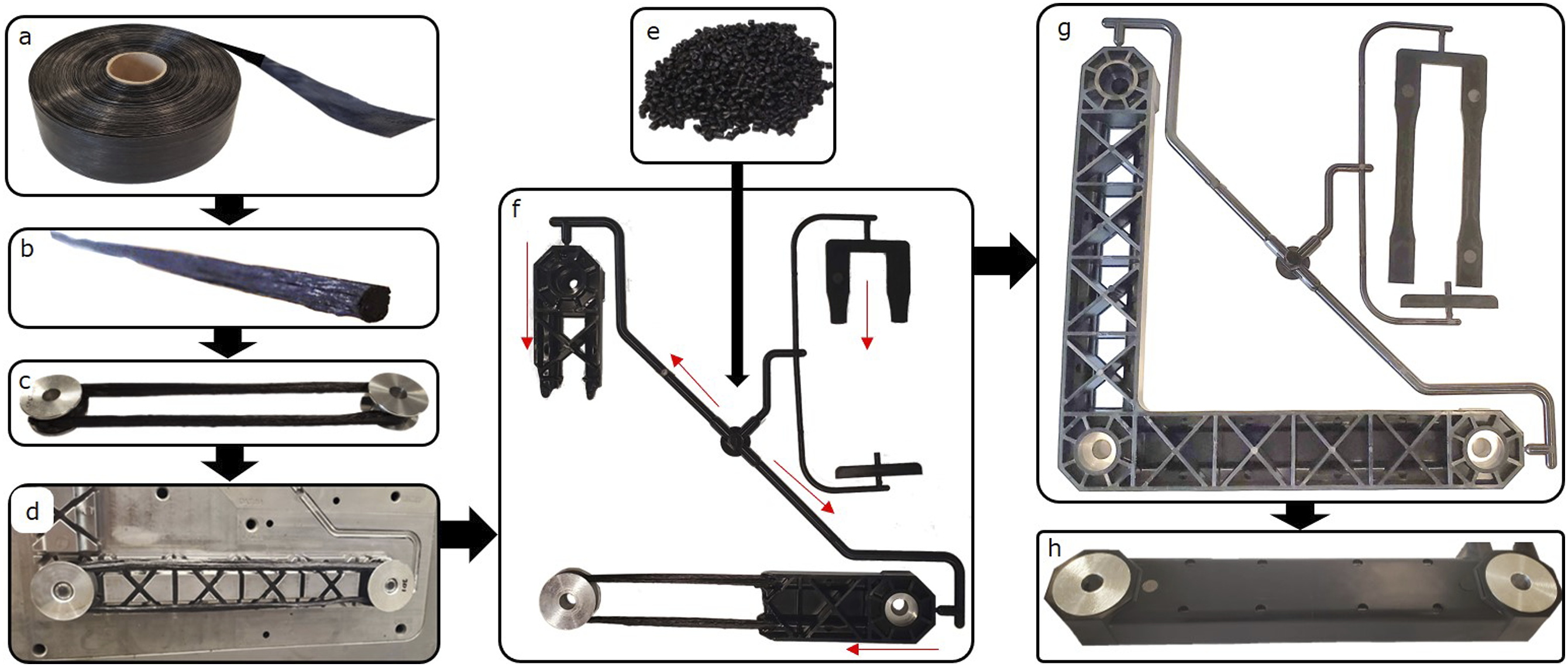
Sample Production
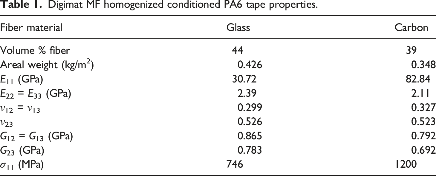
Digimat MF homogenized conditioned PA6 tape properties.
Dumbbell coupons
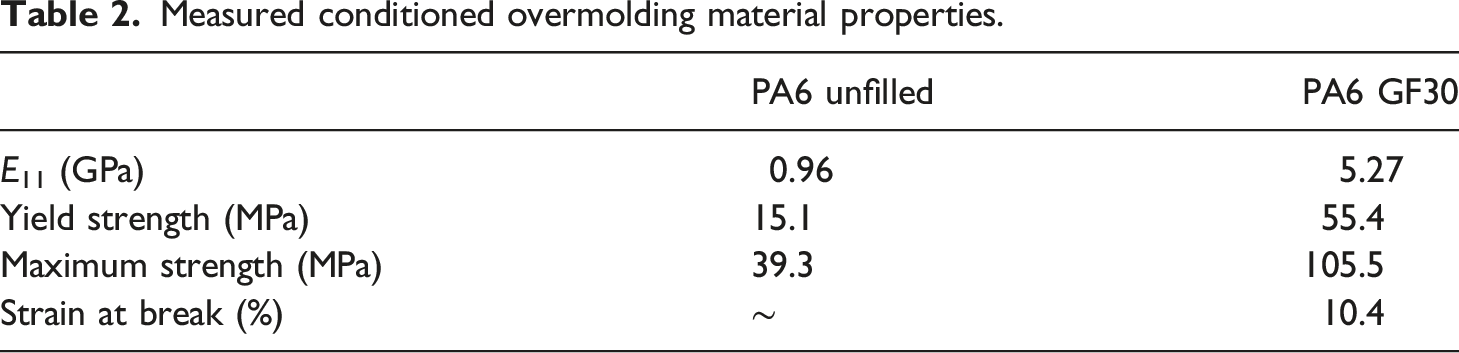
End-gated ASTM D638-14 dumbbell coupons were molded simultaneously with the parts. The samples were tested in tension and strain was measured using digital image correlation (DIC). Representative non-linear stress strain curves from the two overmolding materials are shown in Figure 2 and the measured properties are reported in Table 2. Stress-strain behavior above the 0.2% yield stress was tabulated for use in plasticity material models in ABAQUS. Samples were tested from different molding and conditioning batches and little variation was found. It should be noted that molded dumbbell coupons have fiber and polymer alignment in the flow direction. Typical stress strain response of the studied overmolding materials measured from end-gated dumbbell coupons. These results show that the short glass fiber filled PA6 is significantly stiffer and stronger than the unfilled PA6 which experienced significant plastic deformation without ultimate failure. Measured conditioned overmolding material properties.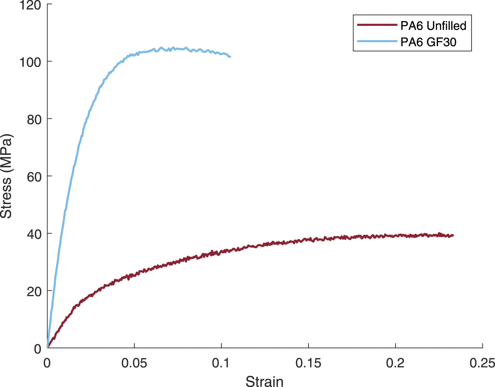
Finite element model setup
The tensile and bending responses of the beams were simulated using finite element models in ABAQUS. To simplify meshing, small fillets, and draft angles were removed from the solid model of the representative beam geometry. Additional wraps around the bushings anchoring the tow ends were not modelled for simplicity. The models utilized symmetry where possible by dividing the bending test model in half and the tensile test model into quarters, as shown in Figure 3. Tension and simply supported, three-point bending load cases and finite element model setup with symmetry planes indicated.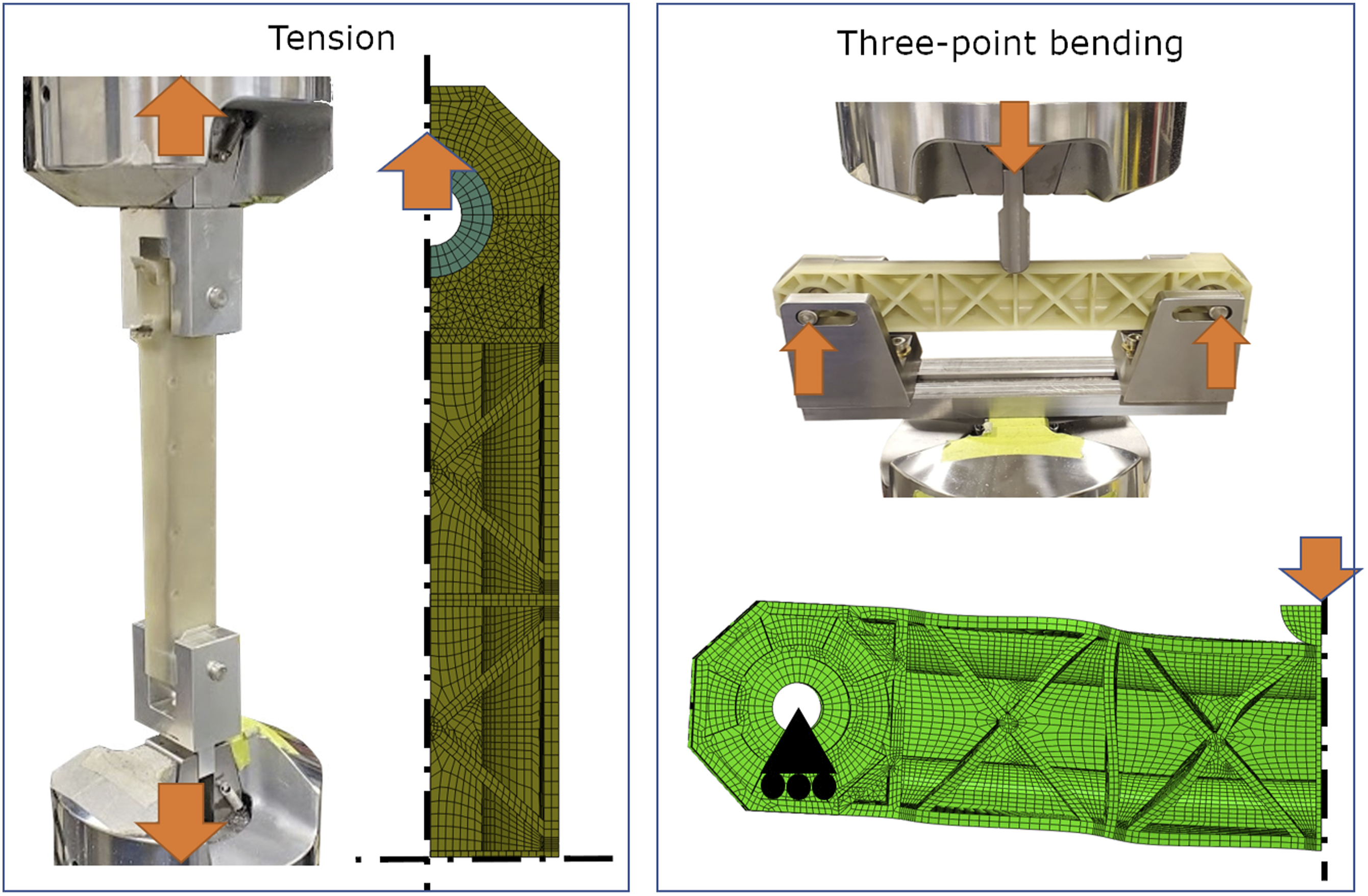
The central C-channel and rib region of the beam was meshed with C3D8R elements while the load introduction region used some C3D10 tetrahedral element regions where the transitional geometry was too complex to be represented by hexahedral elements. The tow was meshed with fully integrated C3D8 elements to prevent hourglassing in the highly anisotropic material. The axial Poisson ratios of the overmolding materials were calculated to be slightly above 0.5, but for modelling were reduced to 0.45 to prevent errors due to incompressibility.
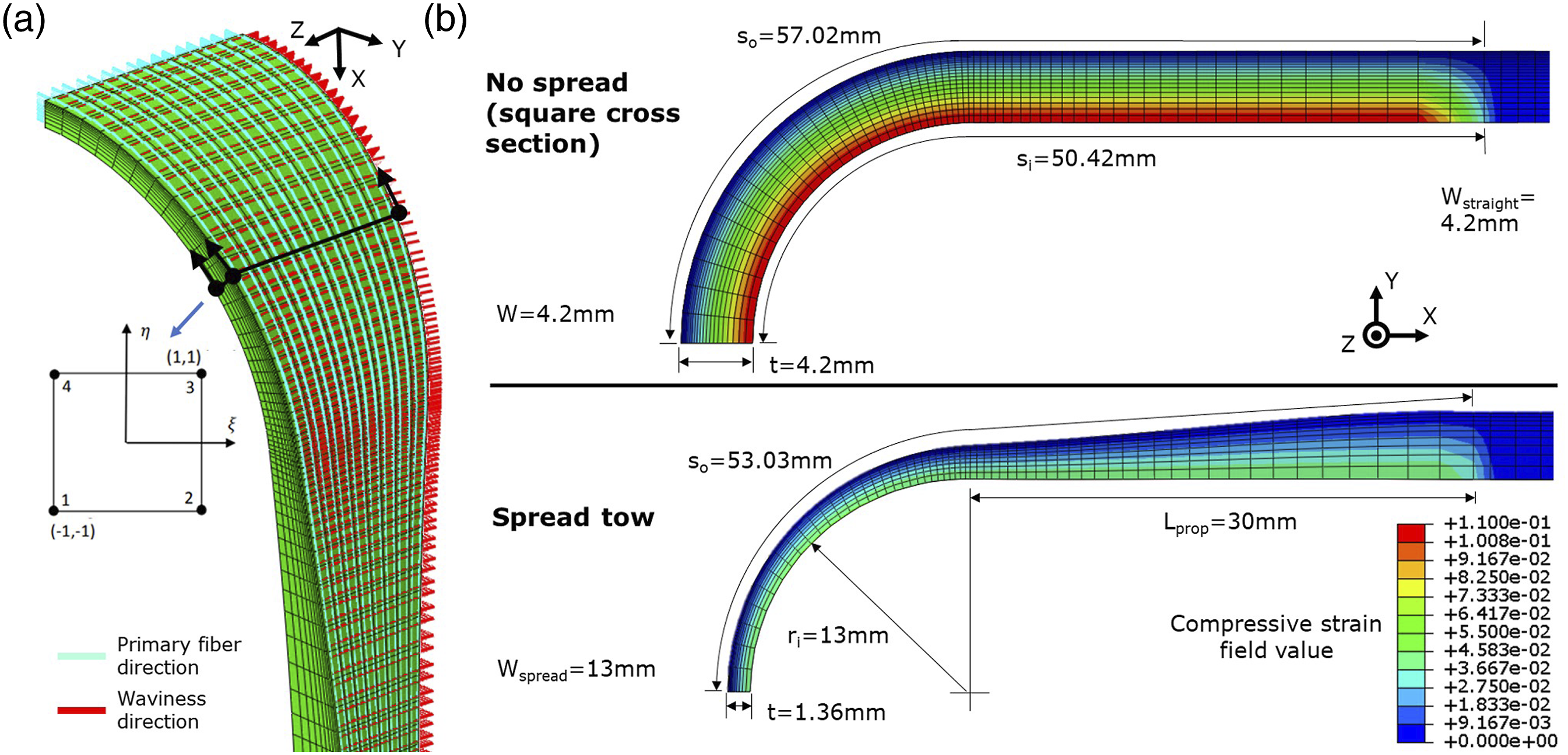
The effect of spread fiber orientations within the tow can be investigated by comparing assumed fiber directions from the centerline of the tow path with those predicted by mapping fiber orientations from the edges of the rectangular section of the spread tow. A script was written to map the orientations from each edge of the tow geometry to each element, regardless of element shape. For each solid element, the closest discretized segment of each boundary edge is found and fit to a plane. Two-dimensional shape functions in natural coordinates, as shown in Figure 4(a), are then used to quantify the influence of each of the boundary edges as described by equation (1). Their orientations are weighted and summed as exemplified by equation (2) for the global X direction of the interpolated primary orientation. Mapped orientations are shown for a sample spread tow mesh in Figure 4(a). (a) Orientations mapped from tow geometry edges. for an example spread tow mesh. Orientations parallel to mesh surface are hidden. The tow path centerline shown was also used to map simplified orientations, uniform in Z, for comparison to edge interpolated spread tow orientations. (b) modelled tow dimensions and mapped compressive strain field from wrapping for association of corresponding effective properties.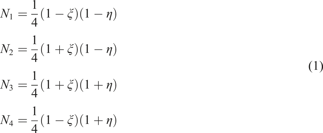

In all tests, the interaction between the tow and overmolding materials were treated as perfectly bonded using a tie constraint. Previous tests did not show significant debonding before tow fracture. In the tensile tests, contact between the aluminum bushings and the polymer and composite materials was modelled as hard contact with a tangential penalty friction coefficient of 0.3. Load was introduced with an applied displacement to the load introduction bushing while preventing out of plane rotation of the bushing.
In bending tests, the load introduction bushing was tied to the overmolding and tow which neglects bushing contact effects. The straight tow geometry was used for simplified meshing as spread effects were assumed to be negligible in this load case, especially if neglecting bushing contact. Contact between the 10 mm radius loading nose and the center of the part was also defined with hard contact and a tangential penalty friction coefficient of 0.3. The bushing control point was simply supported allowing for movement along the beam axis and rotation about the bushing axis and the vertical axis to match the previous experimental setup.
Tow failure is determined as when the stress in the fiber direction of the straight fibers exceeds the maximum stress of the material. Previous works have found that fiber straightening is suppressed by straight fibers surrounding wavy composite materials leading to underestimates of ultimate strength.23,24 In addition, the relatively high plasticity of the thermoplastic tow matrix 25 will further increase strain to break in shear and transverse normal stress. Therefore, regions of straight fibers are assumed to suppress the strain such that the failure stress of the less stiff wavy composite cannot be reached before tensile failure in the straight fibers. Due to the large gradient in material properties and stresses in the tow due to fiber waviness, strength is implemented by extracting fiber direction stresses through the thickness of the part at simulation time steps. These nodal stress values are fit to a 6th order polynomial to estimate the peak stress at the outer surface and interpolated between time steps to determine the load at which outer surface stress exceeded the fiber direction material strength (σ11). With sufficient element density, the results were shown to be mesh independent by comparing models with 10 and 20 elements biased through the tow thickness direction which resulted in a 1% difference in predicted strength and negligible difference in stiffness which is very similar to previous work 20 . Subsequent tow meshes were seeded with 10 elements with a bias factor of 5 toward the side with higher stress. In regions without waviness, strength was implemented by terminating the simulation with the XIT command in a user field when fiber direction stress exceeds σ11. Overmolding material properties were modelled as uniform throughout the part and short fiber orientations were not considered. Residual stresses from injection molding were also assumed to be negligible. Weld lines were also not modeled due to processing condition dependence. Overmolding material strength, which was not modelled in this work, requires further characterization for accurate modelling in complex load cases, so this was not implemented in this work.
Fiber waviness theory and calculation
When a thick composite is curved, for example around a load introduction bushing, a length discrepancy occurs between the inner fiber path and the outer fiber path. The unidirectional fibers are inextensible, and their transverse motion is relatively unconstrained when the matrix is in a fluid state. The length discrepancy leads fibers within a bundle to tend to spread and locally buckle as shown in Figure 5. Tow spread is effectively the first low frequency buckling mode which occurs when the fibers are not transversely constrained. However, not all length discrepancy can be compensated by transverse spread due to external constraints and the viscous resistance of the resin matrix. This results in a combination of tow spread and local waviness. While prediction of processing parameter effects on tow spread is beyond the scope of this work, it is critical to understand the resulting effects of spread and waviness on performance. Fiber waviness is observed on the inside of a tow preform wrap around a load introduction bushing while outer fibers remain straight. The part shown is a 1 × 3 carbon tow reinforcement with the bushing removed.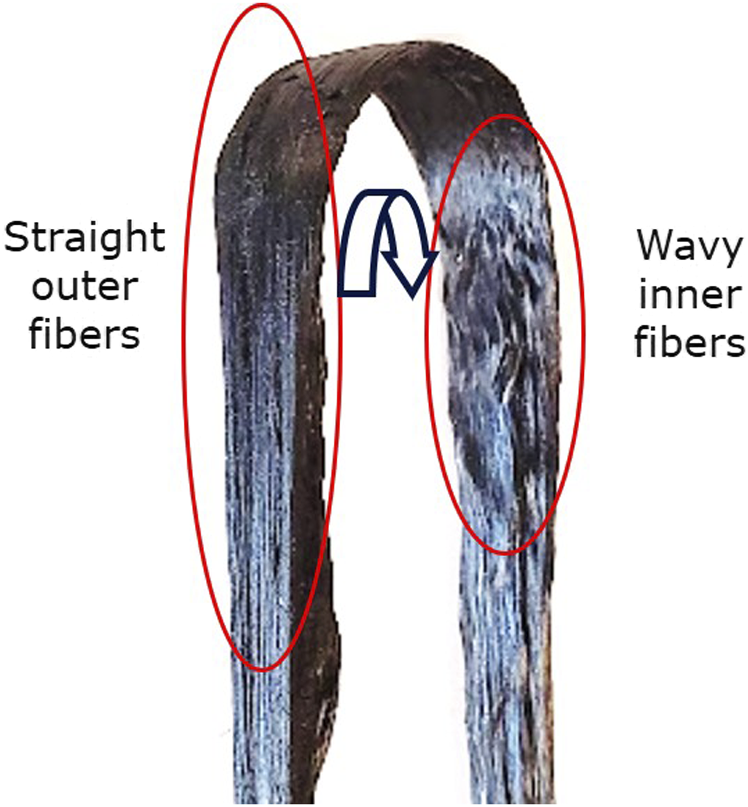
The tow cross-sectional area was calculated to be 17.6 mm2 from the supplier provided tape data. The consolidated tow was modelled as a square in the central region of the part for simplicity of meshing. To quantify spread, the tow is assumed to spread with uniform radial thickness across the width and constant swept cross-sectional area. Spread tow width was measured to be approximately 13 mm for 1 × 3 tow specimens. From the conservation of cross-sectional area, the resulting tow thickness reduced to 1.36 mm from 4.2 mm in the original square cross section. The spread tow shape was modelled using a constant cross section sweep. The swept section wrapped around the 13 mm bushing radius and assumed 30 mm of propagation into the straight region of the tow as shown in Figure 4(b).
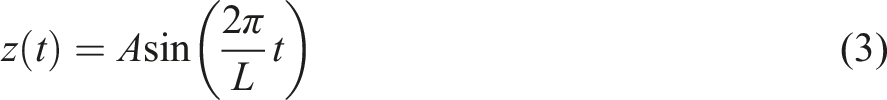
The buckling leads to local fiber waviness with amplitude, A, in the Z direction which was modelled as a sinusoid with period L along the wavy fiber path coordinate t, as shown in equation (3) such that effective elastic properties of the material could be estimated using Hsiao and Daniel’s uniform fiber waviness model.
19
To quantify the amplitude of the waviness, the compressive strain induced during manufacturing, ϵ, is calculated in equation (4) from the relative difference between the outer, straight fiber path length (s
o
) and the wavy path length (s
i
). The values of compressive strain are linearly interpolated between the inner and outer paths as a field value which is associated with corresponding material properties in the finite element model as shown in Figure 4(b). The compressive strain is much higher when considering a tow cross section which does not allow spread leading to increased local fiber waviness.
The fibers themselves do not significantly stretch or compress and the wavy fiber length (l
wavy
) must equal the straight fiber length (l
straight
) which is equal to the outer fiber path length (s
o
). Wavy fiber length is calculated from equation (5) and equated to the straight fiber length in equation (7).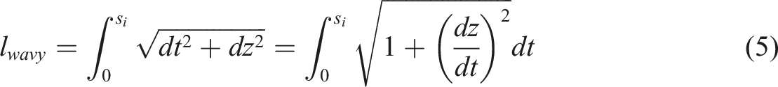

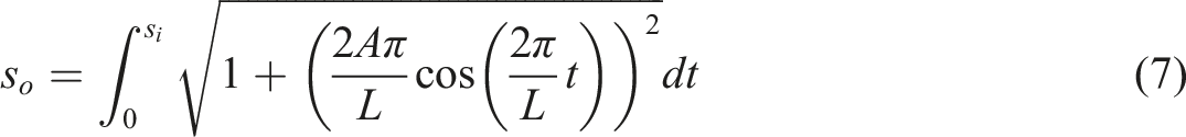
The resulting integral is numerically solved for waviness amplitude, A, while using an assumed a waviness period L, which results in a complete sinusoidal oscillation. Previous work 20 showed that the resulting amplitude ratio, A/L, is independent of the chosen waviness period so any value of L will result in the same amplitude ratio and thus the same effective properties. The period is arbitrarily set to s i to solve for A. Equation (7) is solved to determine amplitude ratios corresponding to values of compressive strain within the ranges caused by the tow wraps of interest. These amplitude ratios are then used within the Hsiao and Daniel model to calculate homogenized effective anisotropic elastic properties associated with corresponding compressive strain field values through the thickness of the tow and are imported to a field dependent anisotropic elastic material model in ABAQUS. The straight region of the tow beyond where fiber waviness has propagated was modeled with the uniform straight fiber composite properties reported in Table 1, not considering difference in compressive behavior.
Results
Tension in no-tow samples
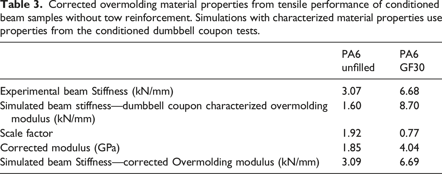
Simulated tensile load displacement results compared to experimental results for molded samples without tow reinforcements showed a significant difference in effective stiffness indicating that the overmolding material properties were not sufficiently characterized by molded tensile coupons alone. Injection molded material behavior has significant processing dependence, but the focus of this work is on tow reinforcement performance. To better represent the process induced properties of the overmolding material and isolate the effect of tow reinforcement modelling techniques, the overmolding material modulus was scaled to match the experimental tensile data from beam samples without tow reinforcement, as shown in Figure 6. The material in the beam samples without tow reinforcement experienced more similar process history and loading conditions to the samples with tow reinforcement as compared to the dumbbell tensile samples. Despite being manufactured at the same time, the difference in local thermal and flow conditions has potential to cause differences in polymer crystallization, density, and short fiber orientations. Additional test geometries with different spans would also validate these material property assumptions under load cases with different moment and shear force combinations, but additional injection molds would be necessary. The yield stress was also scaled by the same factor. The scaled properties, shown in Table 3, were used in further simulations with tow reinforcements. Tensile load-displacement response of samples without tow reinforcement is poorly predicted by the dumbbell coupon characterized properties (dotted lines). To investigate the tow reinforcement effects on the structures, overmolding material properties are compensated by scaling the overmolding stiffness (dashed lines) to match the experimental load displacement curves (solid lines) more closely. Corrected overmolding material properties from tensile performance of conditioned beam samples without tow reinforcement. Simulations with characterized material properties use properties from the conditioned dumbbell coupon tests.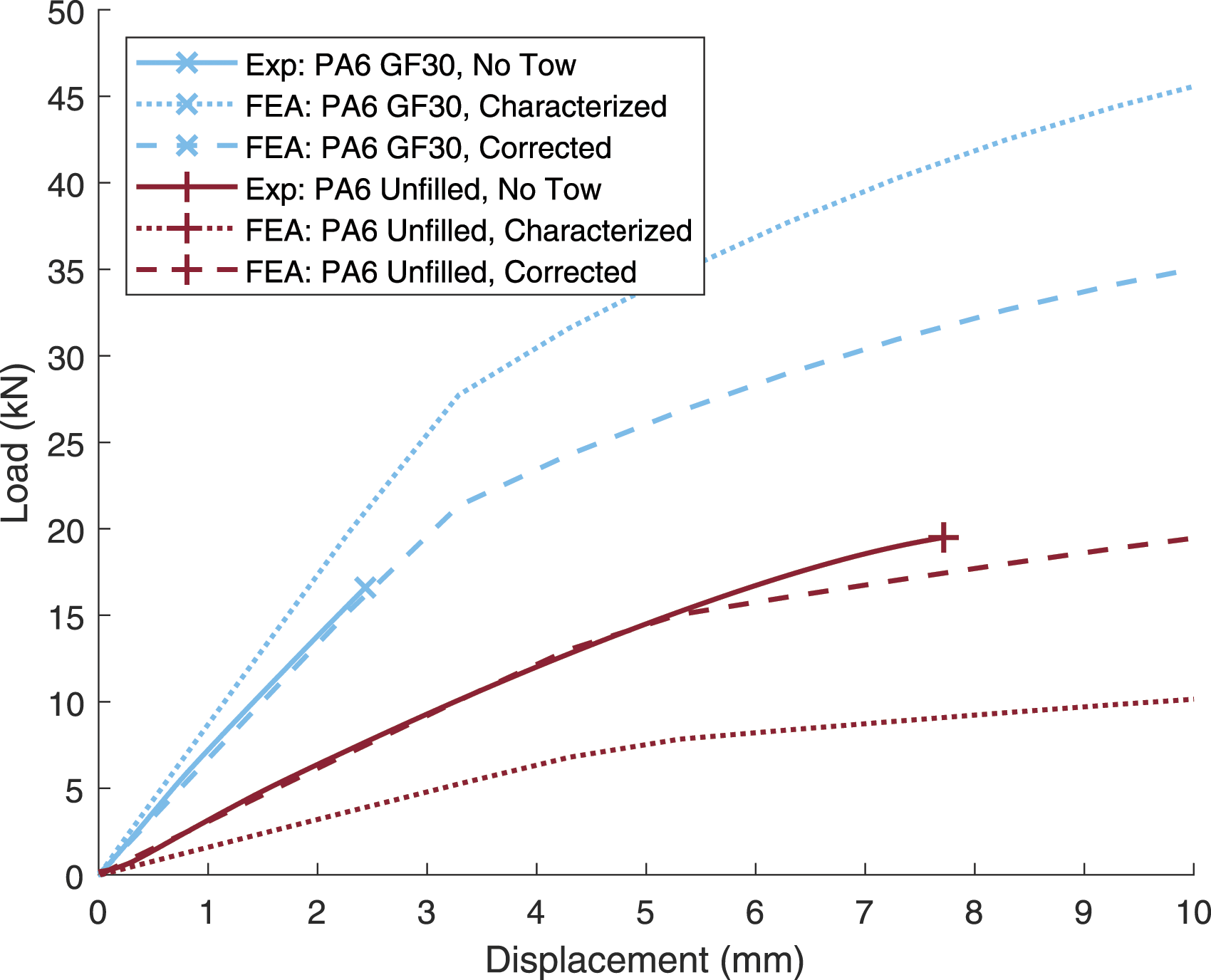
Tensile performance with tow reinforcements
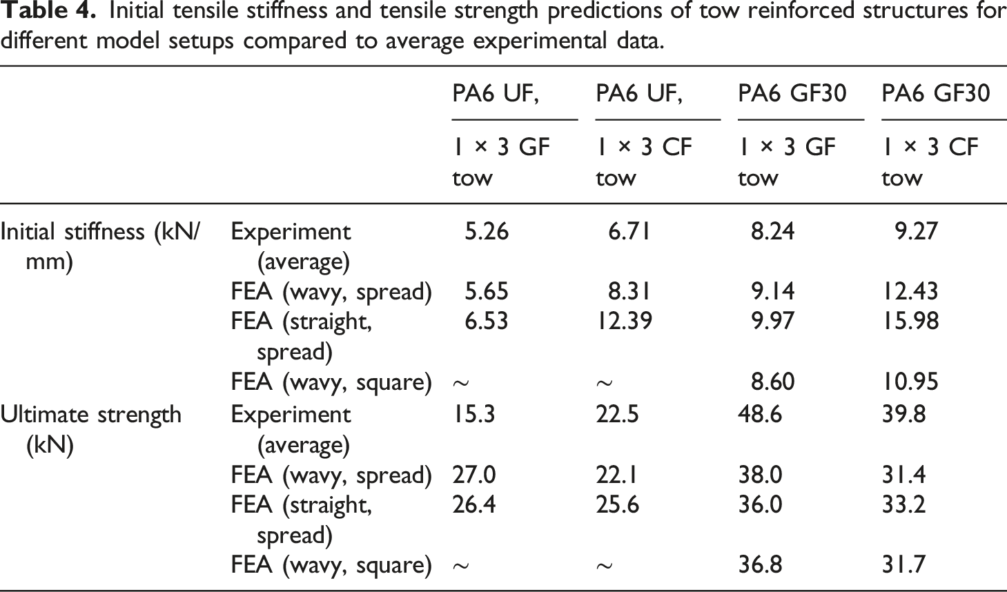
The tensile load-displacement results for models of parts with tow reinforcements are plotted compared to experimental results in Figure 7. Initial stiffnesses and ultimate strengths of tow for different modelling conditions are presented in Table 4. Simulations with spread tow but neglecting fiber waviness are shown to significantly overestimate stiffness in all cases studied. Tensile stiffness of glass fiber tow reinforced samples was overpredicted by 24.1% and 21% respectively for unfilled and glass filled PA6 overmolding. Stiffness of carbon fiber tow reinforced samples was overpredicted by 84.6% and 72.5% for unfilled and glass filled PA6 overmolding respectively. However, accounting for fiber waviness, stiffness was only overpredicted by 7.4% and 10.8% (unfilled and glass filled PA6 overmolding respectively) and 23.7% and 34.1% in carbon fiber tow samples (unfilled and glass filled PA6 overmolding respectively). Tensile load displacement response for unfilled PA6 (a) and glass filled PA6 (b) overmolded beams with various tow reinforcements. Finite element models are represented by dotted and dashed lines and representative experimental data is represented by solid lines. Initial tensile stiffness and tensile strength predictions of tow reinforced structures for different model setups compared to average experimental data.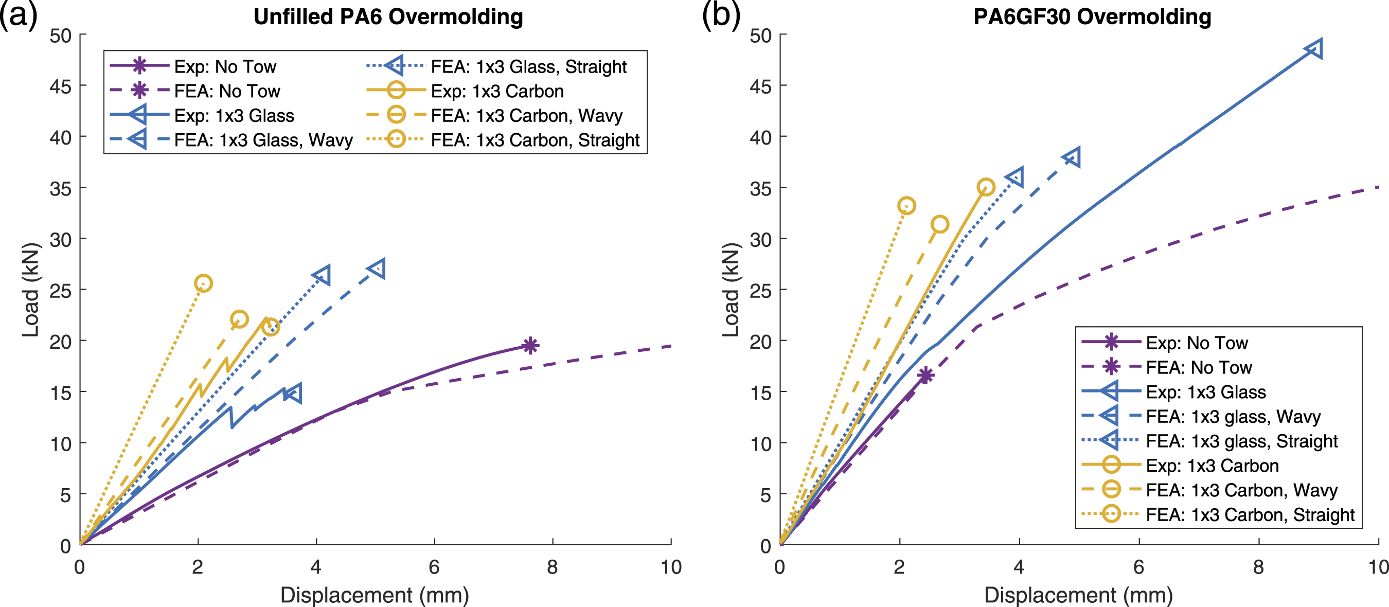
Strength in samples overmolded with unfilled PA6 was significantly lower than predicted due to premature overmolding material failure on the sides of the load introduction points. Cracks were observed during testing that correspond with the drops in load seen in the experimental load-displacement curves. This occurred despite the high elongation to break predicted by the tensile dumbbell coupons. Strength predictions in the PA6 GF30 samples were approximately 21% underpredicted for both carbon and glass tow reinforcements. Failure in the PA6 GF30 samples typically occurred near the weld line which may have led to stress concentration but this also corresponds with the location of the peak tow stresses when not considering overmolding material property variation.
If tow spread is prevented during manufacturing, the compressive strain imposed on the inner fibers of the tow is much greater (Figure 4) leading to increased waviness. When the tensile response of a part with constant square tow cross section was simulated, this increased waviness led to a 5.9–11.9% decrease in effective stiffness with greater stiffness reduction with the more anisotropic carbon fiber tow material as shown in Figure 7 and Table 4. However, predicted strength was similar to the spread tow simulations.
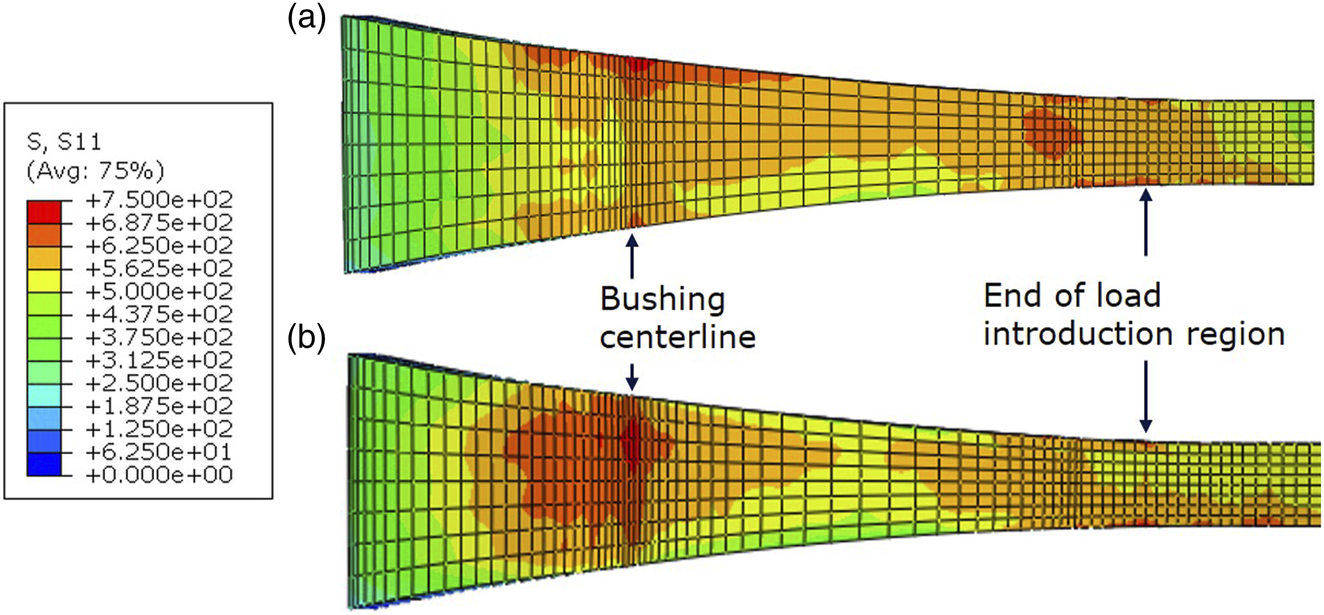
Neglecting fiber spread orientations and using orientations mapped from the centerline of the towpath resulted in nearly identical stiffness behavior but 5.3% higher strength as compared to the same model with mapped spread fiber orientations as shown in Figure 8. The stress fields plotted in Figure 9 show that in the mapped tow model, more stress is carried by the spread fibers while the model with centerline fiber orientations had higher stress in the center of the tow. Also notable is the elevated stress near the end of the load introduction region. Spread versus square tow cross section tensile performance prediction comparison for PA6 GF30 overmolded samples. Fiber direction stress fields in models with (a) Mapped fiber orientations as compared to (b) Centerline fiber orientations at the time step before failure occurred for each model. The results shown are for models with glass fiber tow and short glass fiber filled overmolding material.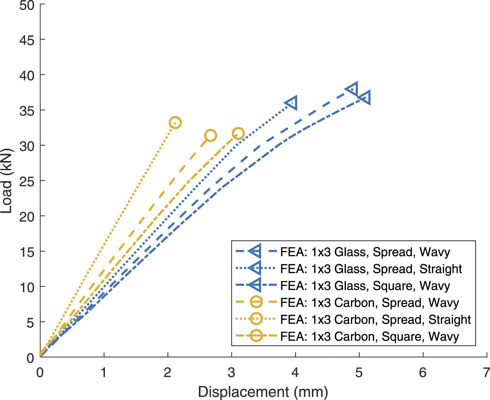
Bending performance
The three-point bending tests result in load-displacement curves, shown in Figure 10, for various material and tow combinations. Models simulating parts overmolded with unfilled PA6 were relatively accurate, only overpredicting the effective bending stiffness at higher loads, at which point rib buckling was significant. Experimental tests showed dominance of the overmolded shear web on bending strength where failure occurred much earlier than FEA predicted tow failure opposite the loading nose, but overmolding strength was not included in the model. The typical regions of high shear web stress in the finite element models, regardless of overmolding material, also corresponded to shear web failure locations observed (Figure 11). Load displacement results of simply supported three-point bending models (dashed) and representative experiments (solid). Beams overmolded with unfilled PA6 (a) and 30 wt% glass fiber filled PA6 (b). Deformation comparison in bending for a glass filled PA6 beam reinforced with 2 × 3 glass fiber tow between experiment before failure (a) and finite element model at 13 mm displacement (b). Whitening from high stress regions near rib intersections is observed in the experimental results corresponding well with the finite element model.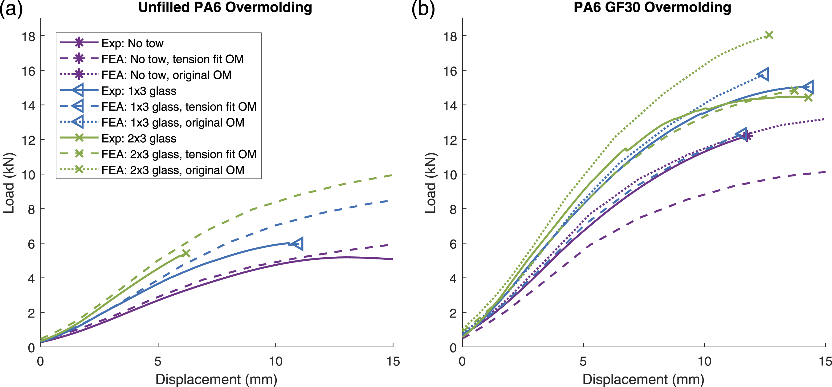
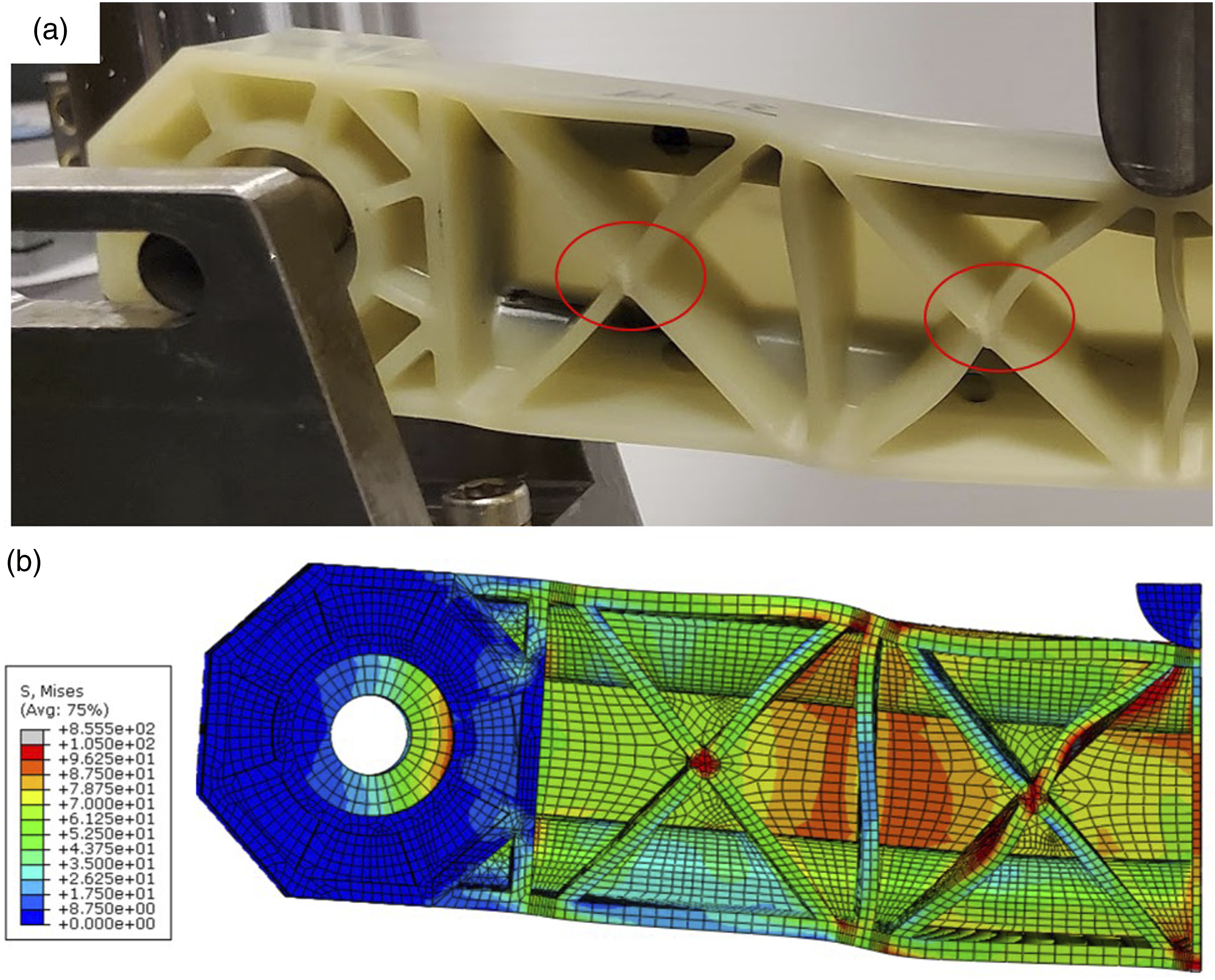
Bending stiffness of the samples overmolded with PA6 GF30 was greatly underpredicted by the finite element models using the tension fit overmolding properties (Figure 10(b)). However, the original dumbbell characterized overmolding properties provided a much better performance for this material except in the 2 × 3 glass tow variation. Experiments observed relative independence of bending behavior on the amount of tow included, but the simulation predicted significant bending stiffness and strength improvement. The failure location opposite the loading nose was accurately predicted in the glass filled overmolded samples. The stress distribution observed in the model showed high stresses at rib interfaces where whitening of the overmolding material occurred during testing as shown in Figure 11. This validates the predicted behavior of the rib geometry which is commonly found in hybrid molded components.
Discussion
Performance effects of fiber waviness
It is clear from the simulation results of models not considering fiber waviness, that tow reinforced hybrid molded composite structure tensile stiffness is greatly overpredicted. Accounting for fiber waviness through mapped compressive strain fields and a Hsiao and Daniel fiber waviness model greatly improved tensile stiffness prediction. More anisotropic tow reinforcement material also suffers from greater overprediction of stiffness, especially when neglecting waviness.
Modelling tow reinforcements without accounting for fiber waviness could result in an inaccurate stress distribution within the tow and therefore should not be used without careful consideration for failure prediction of tow reinforced parts. Models with no waviness are more representative of a tow which is laid up in many thin layers rather than a single bundle of composite material. These results show that using many thin wraps increases stiffness, but the spread tow geometry has similar strength compared to a single tow wrap which requires significantly less manufacturing time. Simulations also predict that the use of higher strength but more anisotropic tow reinforcement materials can reduce part strength when tow failure dominates. This trend was also observed in the previous experimental data for glass fiber filled overmolding material but not in the unfilled overmolded samples where overmolding failure occurred before ultimate part failure.
Tow spread effects on tensile performance
Results also showed tensile stiffness reduction from non-spread tow due to the increased fiber waviness and a reduced region of straight fibers which carry high stress. However, the effective stiffness reduction is relatively small despite almost double the compressive strain occurring on the inner radius. Thus, in most cases, tow spread should be allowed, and space should be allocated for spread tow within the part geometry wherever tow path curvature is present. Additionally, while spread fiber orientation mapping did not have significant effect on the stiffness, the stress distribution changes influencing the predicted failure behavior. A simplified model without mapped spread fiber orientations may be reasonable in some cases but the orientations should not be neglected when examining ultimate strength. It should be noted that the magnitude of performance overestimation by simulations without considering fiber waviness and spread is geometry and material dependent. This also motivates investigation into predicting process dependent spread behavior of the tow such that designers can more accurately predict part performance and anticipate the amount of tow spread for which to plan.
Overmolding material property effects
The change in effective tensile stiffness in the glass filled overmolded samples during loading is also captured by the model and corresponds with the onset of plasticity in the overmolding material near the transition between the C channel and the load introduction anchor region. However, the load at which the reduction in stiffness occurs was predicted to be much higher than the corresponding load observed in experiments. Tensile stiffness is still overpredicted in samples with glass filled overmolding materials, possibly due to changes in flow induced fiber orientations in the overmolding material which were not accounted for within the models.
Bending performance of the unfilled PA6 overmolded samples was relatively well captured while neglecting load introduction effects at the ends of the part. Thus, these effects can be neglected where tension is not of concern. The bending performance was not as accurate at higher loads where rib buckling became more significant. More accurate modelling of the overmolded rib buckling behavior and yielding behavior may be required to achieve more accurate load-displacement response.
However, when using glass filled PA6 overmolding material, the bending load-displacement curves were significantly underpredicted with the no-tow tension corrected properties. This occurs in the sample without tow reinforcement as well, indicating that the error is likely caused by the compensated overmolding material properties determined from the no-tow tensile tests. These material properties had been approximated as isotropic, neglecting local, flow induced fiber orientations and transverse properties. Material which flowed through the thinner mold cavity in the central region of the beam dominates bending performance, but the tensile test evaluates the homogenized properties of the material in the thicker load introduction region as well. The material flowing through the thinner region likely has more similar flow induced fiber orientation to the dumbbell coupons. Bending performance simulations with the original characterized material properties lead to much more accurate bending performance predictions. The addition of more tow reinforcement led to a much greater bending stiffness and strength increase in the FEA models than was experimentally observed. The reason for the experimental responses being so similar among parts with different amounts of tow may have been in part due to the location of the tow within the part or bonding between the tow and overmolding materials, but this requires further investigation.
End-gated dumbbell coupons were generally insufficient for predicting stiffness and failure behavior of the overmolding polymers in the complex geometry of the representative structure. Improved material characterization and failure behavior implementation could further improve tow reinforced part performance prediction. However, using injection molding properties calibrated to parts without tow reinforcement, bending simulations with varying amounts of tow reinforcement capture the initial linear elastic load displacement response. This indicates that the tow reinforcement properties are well captured in a region without waviness. Additionally, when loaded in tension, the calibrated isotropic overmolding material properties used were sufficient to demonstrate modelling techniques for the tensile effects of the tow reinforcement with fiber waviness and tow spreading phenomena.
Conclusions
The present work evaluated the ability of finite element analysis to capture the performance of UD tow reinforced, hybrid-molded structures. Fiber length discrepancies occur when wrapping thick bundles of UD fibers around curved geometries, leading to fiber spread and local fiber buckling and waviness. The methods presented in this work for modelling the effective properties of the tow reinforcement accounting for fiber waviness and spread demonstrated greatly improved performance prediction over models which neglected local fiber waviness. It should be recommended for designers to consider waviness effects for the geometry of interest and consider modifying the geometry where possible to minimize fiber waviness or include sufficient reinforcement to compensate for the reduced properties while still meeting design requirements. Tow geometries without tow spread were predicted to have lower tensile stiffness than tow reinforcements that are allowed to spread in a wrap. While the tow reinforcement can improve bending performance, there is a significant influence of the overmolding material which requires more characterization to accurately predict performance.
Footnotes
Acknowledgements
DSM is gratefully acknowledged for supplying the tape and injection molding resin. The authors would also like to thank Eric Eagon, Jacob Coffing, and IN-MAC for their assistance with sample production.
Declaration of conflicting interests
The author(s) declared no potential conflicts of interest with respect to the research, authorship, and/or publication of this article.
Funding
The author(s) disclosed receipt of the following financial support for the research, authorship, and/or publication of this article: This work was supported by the Ford Motor Company