
Abstract
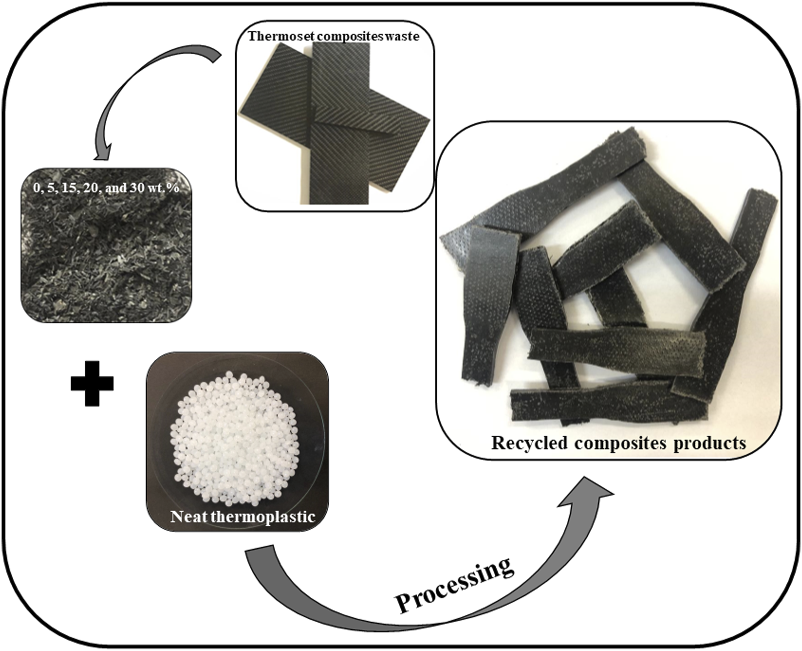
The correct destination of this post-used of carbon fiber (CF) reinforced epoxy composites, is considered noble since their manufacturing process involves high costs and advanced technologies. This work aimed to study the feasibility of mechanical recycling of CF/epoxy composites for nobler applications, such as non-structural internal components, antistatic packaging, or electronics housings. The CF/epoxy residues (CFRPres.) were collected from parts of the aerospace industry, selected, and ground, followed by granulometric separation. Then, the CFRPres. particles were incorporated as filler and/or partial reinforcement in a polypropylene (PP) matrix to obtain a new thermoplastic composite using double-screw extrusion processing, followed by hot compression molding to obtain standardized specimens. The quality of the composites obtained was evaluated through mechanical tests (tensile test, Izod impact strength, and Shore D hardness), thermal (differential scanning calorimetry), electric (impedance spectroscopy, electromagnetic), and morphological characterization (scanning electron microscopy). The addition of 30 wt% of CFRPres. in the PP matrix increases the electrical conductivity by seven orders of magnitude and exhibits semiconductor behavior, and increases 168% in the elastic modulus. As for the electromagnetic properties, increasing the content of residues in the composites also occurs a substantial increase in the relative permittivity. In addition, the development of composites from the incorporation of residues from the aerospace sector proved viable in applications where the impact strength, rigidity, and hardness are crucial, even for the high content of residues aggregate.
Introduction
Carbon fiber reinforced polymer composites (CFRP) have already been used for several decades in aerospace, defense, and high-performance automobile sectors, but in recent years, mass application in market products, such as in high volume in the automotive industry. 1 Thermosetting composites reinforced with CF have proved to be interesting for use in the automotive sector due to their excellent mechanical properties and rigidity, associated with a low density compared to traditional alternatives, in addition to good chemical resistance to solvents, good thermal and dimensional stability even in the presence of moisture.2,3
Therefore, the high employability of these composites means that significant amounts of residues (tailings or scrap) are generated during the manufacture of parts, and they end up being discarded. Among the leading and most used destinations are incineration and sanitary landfills; however, they have a negatively impact the environment, entailing additional costs for producers and suppliers, that is, because it is necessary to pay to dispose of them in these places, the waste is rendered useless forever, generating persistence and accumulation in the environment.4–6 Furthermore, these thermosetting composites reinforced with CF tailings have high added value due to the high technology used in their development, which justifies, even more, the need to develop a methodology for reusing and recycling these thermoset tailings.7–9 According to the study by Geyer, Jambeck, e Law, 10 it is estimated that the production of resins, including thermoplastics and thermosets, and synthetic fibers, since the beginning of their commercialization, in the last 65 years, been approximately 7,800 million metric tons. About half of this amount (3,900 million) was generated in the last 15 years.
However, according to research carried out by Snudden, Ward, e Potter, the increase in the volume of these residues may be allied to the low effort in research on recycling methods for these composites, as they are heterogeneous materials and difficult to recycle. This problem involves not only the aerospace industry but also the automotive industry, which has increasingly used composites in vehicle production. Nonetheless, according to the authors, due to the increasing consumption of composite materials, the introduction of legislation that limits the amount of use of non-recycled materials in new motor vehicles has been created and imposed, as well as the application of higher taxes on the residue that are destined incineration and landfills. These actions are intended to encourage and force industries generated from this type of residue to look for environmentally correct and profitable ways to dispose of their residues.
According to this problem, there is an urgent need to find a suitable and profitable final destination to dispose of these thermoset residues. 11 There are three main methods of recycling thermosets, but they have a high cost in execution; thus, they end up being economically unfeasible to be recycled. 12 The first methodology consists of the incineration process, aiming to recover energy from the heat generated during combustion partially. The second methodology is thermal and chemical recycling, such as solvolysis, pyrolysis, and similar thermal decomposition processes that make it possible to partially recover the reinforcing fibers that can be reused in thermoset composites. 13 And the third existing methodology, more economically viable, is mechanical recycling, which involves grinding the composite to reduce its size, resulting in fibrous materials or powder, which can be incorporated as reinforcement or filler in new composite materials.14–16
Kismet, Dogan, e Wagner 17 used milled residues as a powder from three different electrostatic coatings with a thermoset structure to develop low-density polyethylene (LDPE) thermoplastic composites. The authors added 10, 20, and 30 wt% of these powdered thermoplastic residues to the LDPE matrix using a single screw extruder. The specimens for the mechanical tests were obtained by injection molding. The authors observed a decrease in the tensile strength of the composites compared to the neat LDPE. On the other hand, an increase in the Izod impact strength and the flexural modulus was observed for the composites. Therefore, according to the authors, this study demonstrated that thermoplastic residue could be used as a toughening agent for LDPE.
Another work developed by Kismet and Wagner 18 presents the study of the incorporation of hydrolyzed powder coating from epoxy/polyester, epoxy and polyurethane residues as reinforced in polystyrene (PS) matrix using an extruder and injection molding. According to the authors, the three types of residues decrease the tensile and impact strength with the filler content in the PS matrix increased; this fact may be due to the inhomogeneity of the filler distribution in the matrix, weak interaction of the particles with the matrix, and consequently caused the presence of voids.
Zhang, Liang, e Chen 19 developed a flame-retardant panel by hot pressing from ground thermoset phenolic foam residue and natural wood fibers. From the study results, the authors observed that the final panel showed good physical mechanical and flame-retardant properties and can be applied in fields such as multifunctional furniture, construction, and domestic utensils, among others. Another interesting application using residue from thermoset composites was the study developed by Ribeiro, M.C.S. et al. 20 The authors used fiberglass composite residue (55 wt%), calcium carbonate (16 wt%), and unsaturated polyester (29 wt%) for the development of this recycled polymer-concrete composite. Based on the developed study, the authors verified the cost-benefit potential for application for these thermoset residues, thus aiming at a good application for a high-value residue.
Because of the current situation, with the advancement of research and technology, many thermoset composites have been gradually replaced by thermoplastic composites, as they have presented better advantages, mainly due to the possibility of faster mass production and greater ease of production of recycling. Thermoplastic composites, such as polyamide (PA), poly(phenylene sulfide) (PPS), poly(ether-ether-ketone) (PEEK), polypropylene (PP), have numerous advantages over thermosets, such as more excellent mechanical resistance and damage tolerance, higher service temperatures, possibility and ease of welding, that is, better repair facilities, and less complex processing/preparation.1,21–23
Therefore, with a growing awareness of environmental issues and the subsequent desire to save natural resources, the present research aimed to convert the expensive disposal of thermoset composites residues, which are economically unfeasible to be recycled, into an excellent reusable material, such as thermoplastic composites, which may be used again in the aerospace or automotive industry, but in non-structural applications, for the fabrication of antistatic packaging, or electronics housings. There is a limited number of works related to the mechanical recycling of carbon fiber-reinforced thermoset waste available in the literature. Therefore, this research project aims to present and show the feasibility of incorporating CF-reinforced thermoset composite residues in the form of powder in a polypropylene (PP) matrix to improve the mechanical, electrical, and electromagnetic properties allied to reducing costs in the final product.
Experimental
Materials
Polypropylene (PP), ES 540 specification that corresponds to a heterophasic copolymer of propylene and ethylene, supplied by Braskem (Brazil), with a melt flow index of 42 g/10 min (230 °C/2.16 kg) and a density of 0.9 g/cm³.
The filler was prepared using laminates in plate forms of carbon fiber-reinforced thermoset composites residues (CFRPres: carbon fiber/epoxy matrix 60/40 wt%) that are donated by companies in the aerospace sector of the city of São José dos Campos, SP, Brazil. Laminates are generated during the cuts of structural parts for this sector.
Mechanical recycling of CFRP residue
The CFRP post-use was acquired in plate form (Figure 1(a)). The first part of the process took place with the size reduction of the CFRPres with a grinder with a diamond cutting disc of 115 mm in diameter (Black&Decker); in this way, the length of the CFRPres strips was reduced from 10 cm to approximately 2–7 cm (Figure 1(b)). Subsequently, these pieces were introduced into a knife mill (Rone S-200) in the upper part and comminuted by the knife system, passing through a 6 mm diameter sieve and being deposited in the container attached to the mill at the bottom (Figure 1(c)). CFRP residue size reduction process: CFRP residue as received (a), size reduction using a grinder with a diamond disc (b), and grinding using a knife mill (c).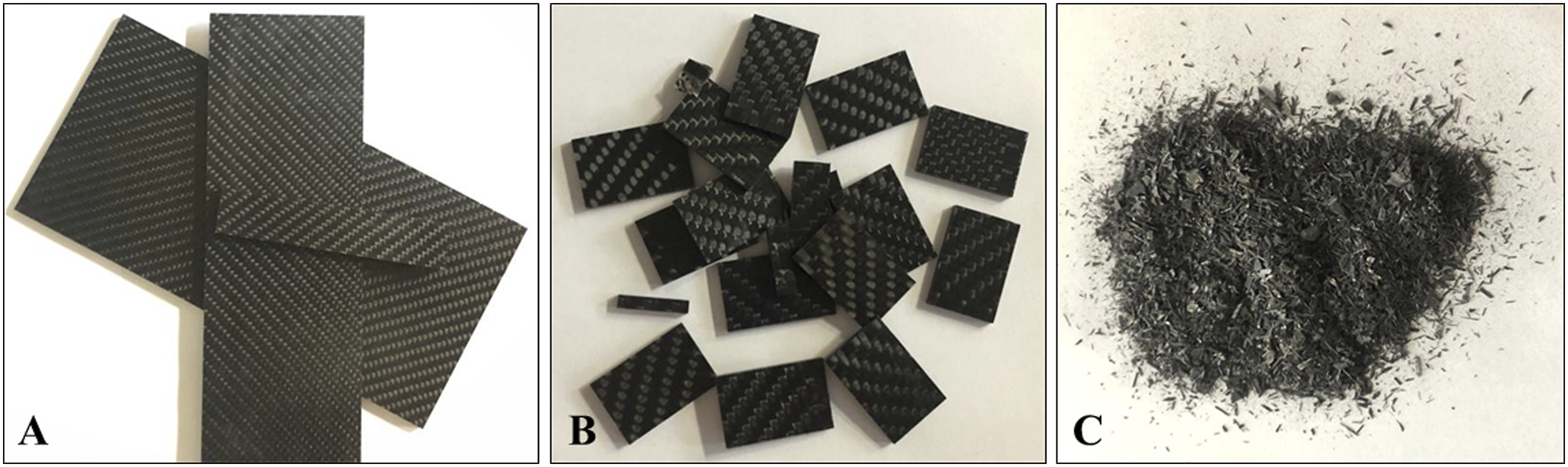
The efficiency of the process was evaluated by analyzing the material weight loss according to equation 1. Efficiency (%) is the percentage of total weight loss by milling, Winitial is the initial weight of composite residue, and Wfinal is the final milled composite weight.

The microscopic analysis of the ground composite was performed using an Optical Microscope (MP-150), with the collection of images with different contrasts and standardization of the scale for the dimensions of the inspected material.
From thermoset composite comminution, the analysis of the granulometric distribution of the ground composite (sizes of the composite granules) was performed through images obtained by the benchtop optical microscope (MP-150) using public domain software Image J®.
Scanning electron microscopy (SEM) was also performed using FEI (Inspect S50 FEI Company® microscope), operated at 20 keV, of the ground granules and the fracture surface of the ground composite, identifying the fiber/resin interface and how this can influence the processing with the new matrix.
Processing of PP/CFRPres composites
The incorporation of CFRPres (0, 5, 10, 15, 20, and 30 wt%) in the PP matrix was carried out by the extrusion process using an AX Plásticos (model AX16:40DR) with a co-rotational twin-screw extruder with processing parameters temperature profile set 200/220/220/230/230°C (from feed zone to die), screw speed of 20 r/min, and the feed hopers-screw speed of 100 r/min. After the extrusion process, the composites were granulated (Figure 2(a)) and dried in an oven at 70°C for 30 min. The nomenclature of the PP/CFRPres composites is related to the amount of residue added, for example, the composition PP/5res corresponds to the composite with 95 wt% of PP and 5 wt% of residues, and PPreproc. correspond to the neat PP that was reprocessed without a load (CFRP residues). Composite processing steps: pellets obtained by extrusion process (a), tensile test specimens (b), and impact test specimens (c) of PP/5res., PP/10res., PP/15res., PP/20res., and PP/30res.composites.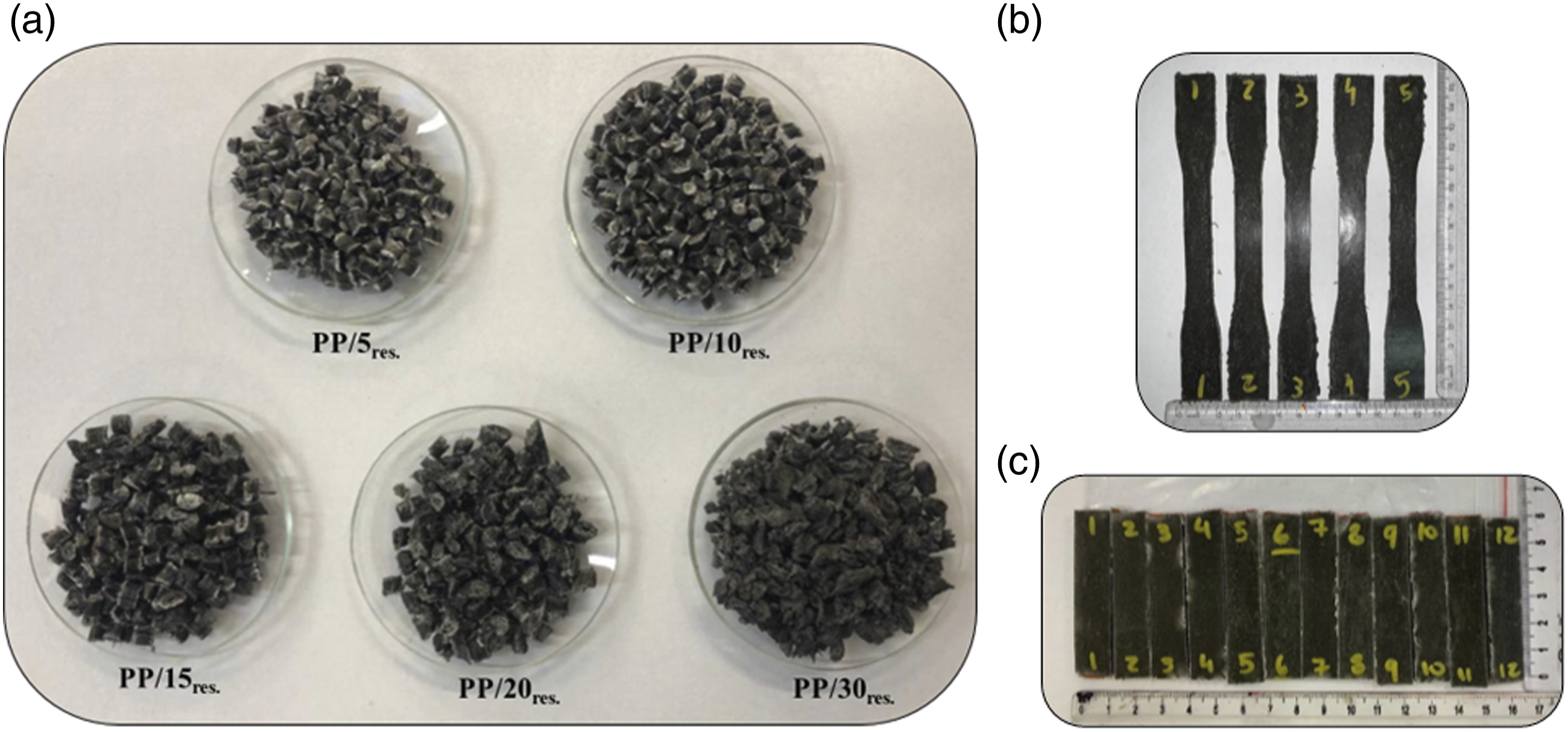
Standardized specimens were molded into 3.2 mm thick plates in a hydropneumatic press (MH Equipamentos, Guarulhos, Brazil, model PR8H) at 230°C with low pressure (minimum pressure, 2 bars) for 5 min, then at maximum pressure (8 bar) for 5 min and cooling down at 2 bar pressure during 3 min. Standardized specimens for the tensile (Figure 2(b)) and impact (Figure 2(c)) tests were prepared using a pneumatic hollow die punch machine (CEAST/Instron).
Characterizations of the PP/CFRPres composites
Thermal characterization
The neat PP and the PP/

The enthalpy of fusion (∆Hm) was directly obtained by DSC in single heating, the melting enthalpy of the 100% crystalline PP (∆Hm°) was taken as 207 J/g, 24 Øres is the weight fraction of the CFRP residue in the polymer. The melting temperature (Tm), ∆Hm, and Xc were obtained for all compositions during the first heating scans.
Mechanical characterization
Izod impact test and tensile tests test was used to determine the mechanical properties of the neat PP and the PP/
Physical characterization
The specimens (length 63.5 mm; width 12.7 mm; 3.28 mm thickness) were submitted to the Shore D hardness test using a digital Shore D hardness tester (Instrutherm, Model DP-400), according to ASTM D2240-15. 27 Measurements were performed on the surface of the samples at distant points.
For statistical analysis, a minimum of five and nine specimens were tested for Izod impact (five tested samples), tensile test (five tested samples), and Shore D hardness (nine tested samples) for each composition. Results were analyzed using one-way analysis of variance (ANOVA) and Tukey’s multiple comparisons test on GraphPad Prism 6 (GraphPad Prism 6 Software® Inc. USA).
Morphological characterization
For the morphological analysis, the PP/CFRPres composites were cryofractured inside a bath of liquid nitrogen for 15 min; then, the fracture was performed. Subsequently, the samples were fixed in aluminum stubs with carbon tape and metalized with a thin layer of a gold-palladium alloy. The metalized samples were analyzed in a scanning electron microscope (SEM) (Inspect S50 FEI Company® microscope), operating at 15 kV with magnifications of ×2000.
Electrical characterization
The AC electrical behavior of the PP/CFRPres composites was analyzed using Impedance spectroscopy and discussed in terms of the total AC electrical conductivity and complex permittivity (or permittivity modulus, or Relative permittivity - εr). The analyses were performed in a Solartron SI 1260 impedance analyzer at room temperature (∼25°C), in a frequency range from 1 to 106 Hz with a tension amplitude of 0.5 V. For the electrical contact and the electrical field application, metallic circular electrodes with a radius of 3.26 mm were deposited by sputtering symmetrically in parallel faces of the samples with a thickness of 3.0 mm. From the measurements, the real impedance component (Z′) and imaginary impedance component (Z″) were obtained and then utilized to calculate the AC volumetric conductivity and the εr.28,29
Electromagnetic characterization
The electromagnetic behavior was evaluated in the X-band (8.2–12.4 GHz) with a vector network analyzer (VNA, Agilent Technologies, model PNA-L N5235 A) coupled with a waveguide (model WR-90). The dielectric constants (relative permittivity (εr) and relative permeability (μr)) with their real and imaginary parts were calculated from the complex scattering parameters using Nicolson–Ross–Weir (NRW) method.
Results and Discussion
Filler characterization after mechanical recycling
Figure 3 shows the images obtained by optical microscopy of the CFRP after mechanical recycling, i.e. after grinding. The images were performed in an optical bench microscope to verify the morphology and distribution of the ground material. It is possible to observe different sizes and shapes of granules; the morphology is irregular with varying lengths, in addition to tangled carbon fiber (highlighted in yellow). Optical microscope image of the CFRP after grinding.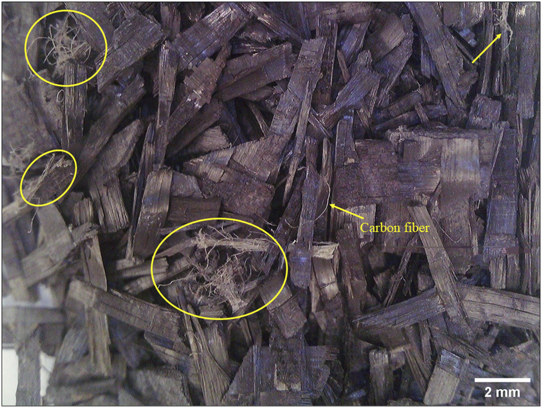
The initial weight of CFRP before the process of griding was 267.9 g, varying in size from 2 to 7 cm. After the mechanical recycling using the knife mill, the final mass was 249.8 g; which corresponds to a weight loss of 6.8% and an efficiency of 93.2%. This value could be considered low, but it can be reduced by sealing the equipment because, during the grinding, the amount of resin powder spread throughout the grinding room and in the equipment during the 10 min of grinding.
CFRP particle size distribution was based on the images obtained by the benchtop microscope, the scale was calibrated, and measurements were taken on 121 composite granules ground by the Image J® software. Figure 4 shows the curve of the total amount percentage of granules by length. The smallest granule measured at 0.697 mm, and the largest at 6.544 mm. It was possible to notice that the most significant granule sizes are distributed between 2.5 mm and 3.5 mm. This could result in an excellent size to process the new thermoplastic matrix composite using the extrusion process and can result in a material with homogeneous reinforcement. CFRP particle size distribution: granule sizes accumulative total by length.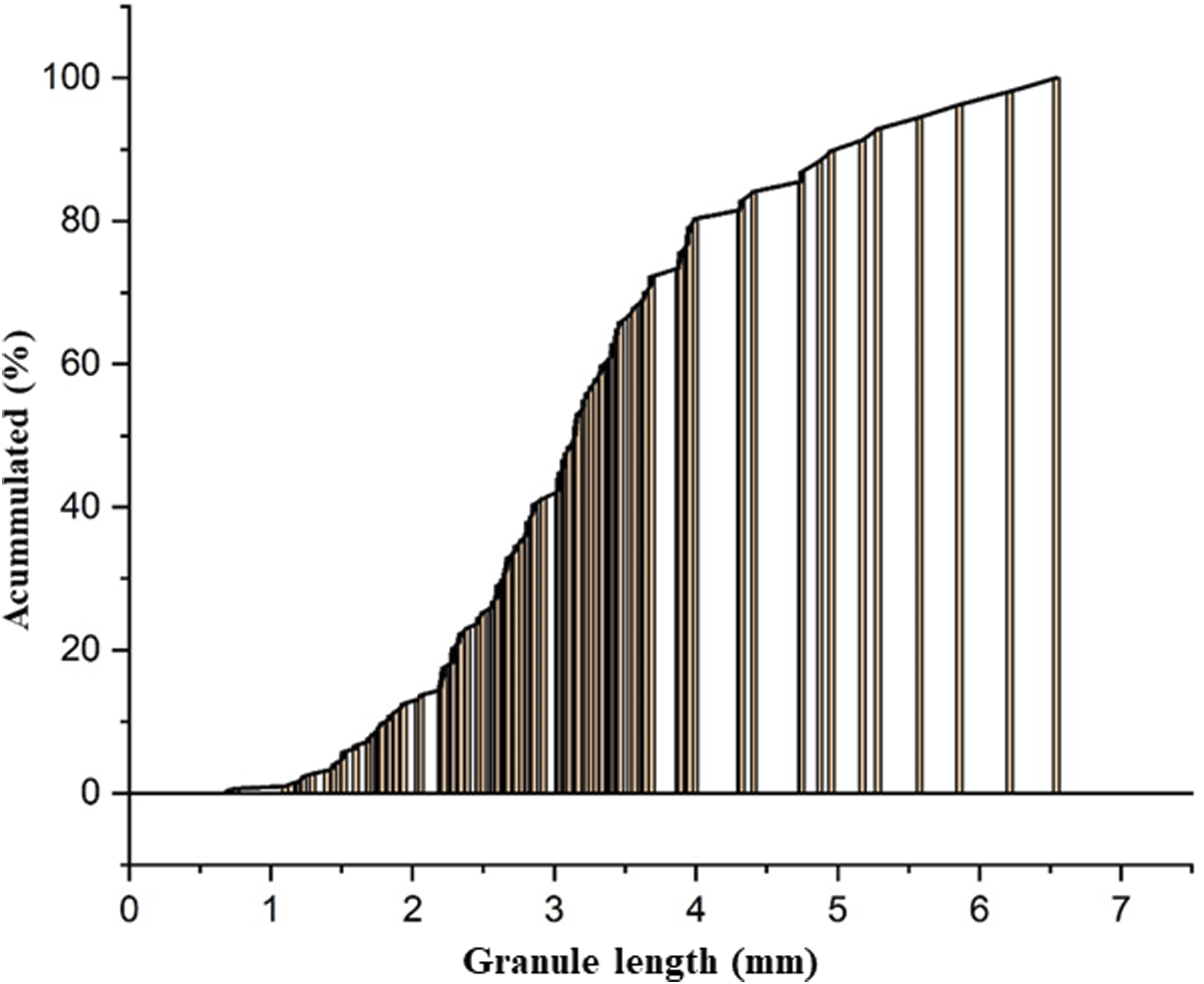
Therefore, a more detailed analysis of the CFRP after the mechanical recycling was carried out using SEM microscope. Figure 5 shows the SEM images of the CFRP after grinding. It is possible to observe a fractured surface after the mechanical recycling using the knife mill, and exposure the carbon fibers present in the CFRP residues. As well as regions with small points covering the sample (highlighted in yellow in Figure 5), probably the epoxy resin powder resulting from the grinding process. It was also possible to verify that the initial CFRP had a good interface between the fiber and the epoxy resin. The ground irregularity could be favorable to prepare a new composite since it allows the new matrix (PP) to adhere to the filler. SEM imagens of ground CFRP: ×200 (a) and (b), ×1000 (c), and ×2000 (d).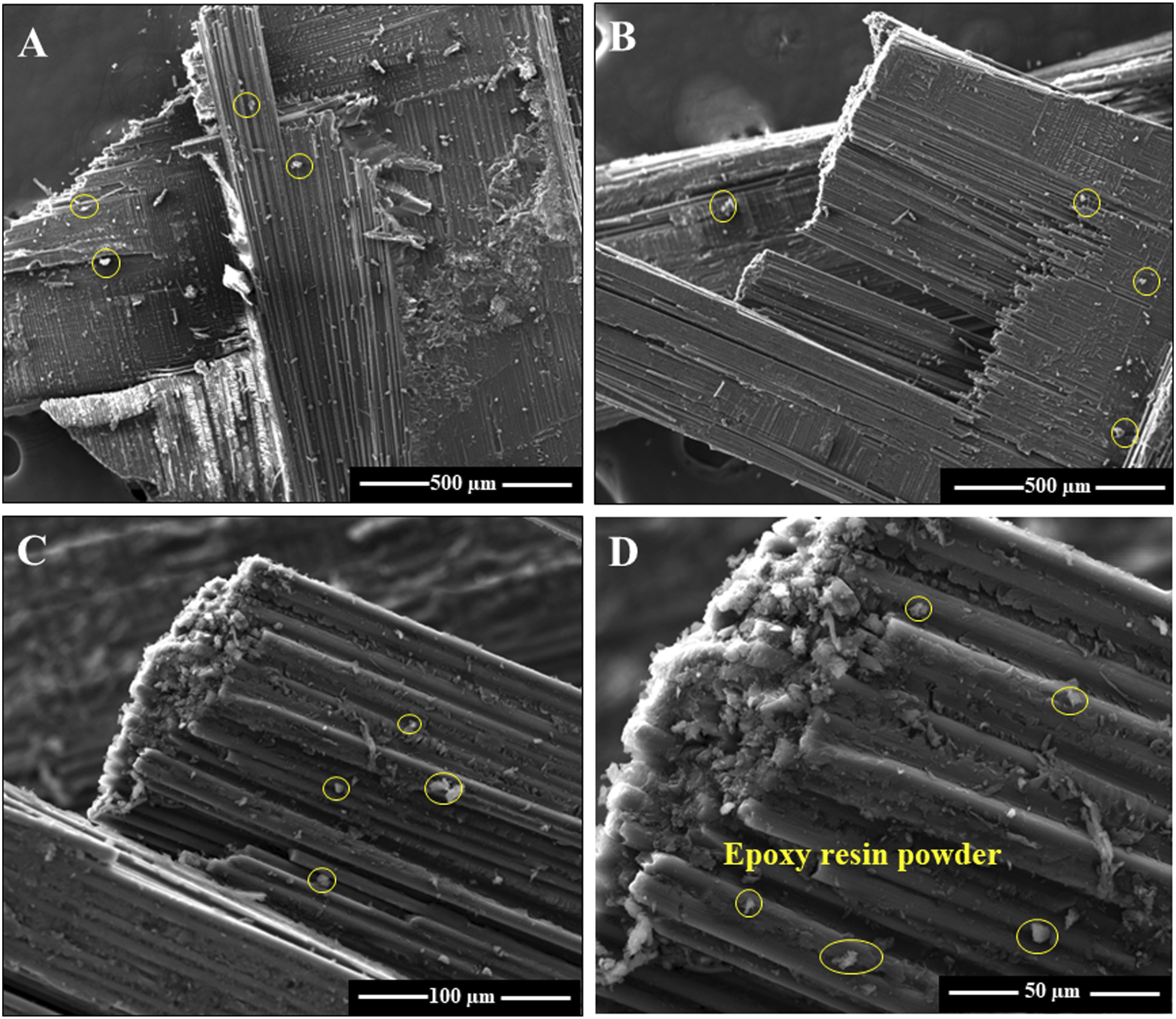
Characterization of the PP/CFRPres composites
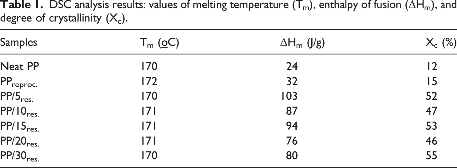
DSC analysis results: values of melting temperature (Tm), enthalpy of fusion (ΔHm), and degree of crystallinity (Xc).
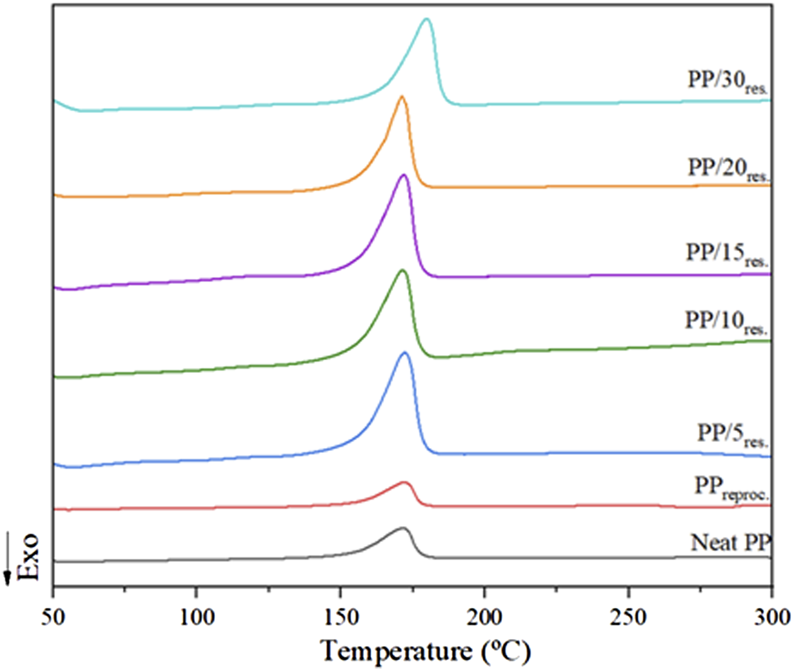
DSC thermograms of neat PP and the PP/CFRPres composites with different contents of filler.
Regarding the composites, no significant changes were observed in the Tm values, indicating good thermal stability of the developed composites. However, a considerable increase in Xc values was observed, showing an increase of 247%, 213%, 253%, 207%, and 267% for PP/5res., PP/10res., PP/15res., PP/20res., and PP/30res. composites, respectively, compared to PPreproc. This increase may be related to the presence of CFRP residues that may have acted as heterogeneous nucleating agents, collaborating with the increase in the Xc values of PP. Similar behavior was observed by Pires, Maia, and Paiva 30 who added 10, 14, and 20 wt% of thermosetting residue particles from the manufacture of high-pressure laminate (HPL) to a recycled PP matrix. The authors observed that as the particle content of thermoset residues added to the PP matrix increased, the Xc values increased, suggesting that the presence of the filler acted as a nucleating agent.
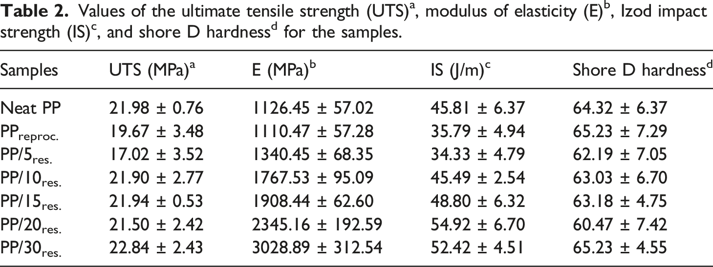
Values of the ultimate tensile strength (UTS)a, modulus of elasticity (E)b, Izod impact strength (IS)c, and shore D hardnessd for the samples.
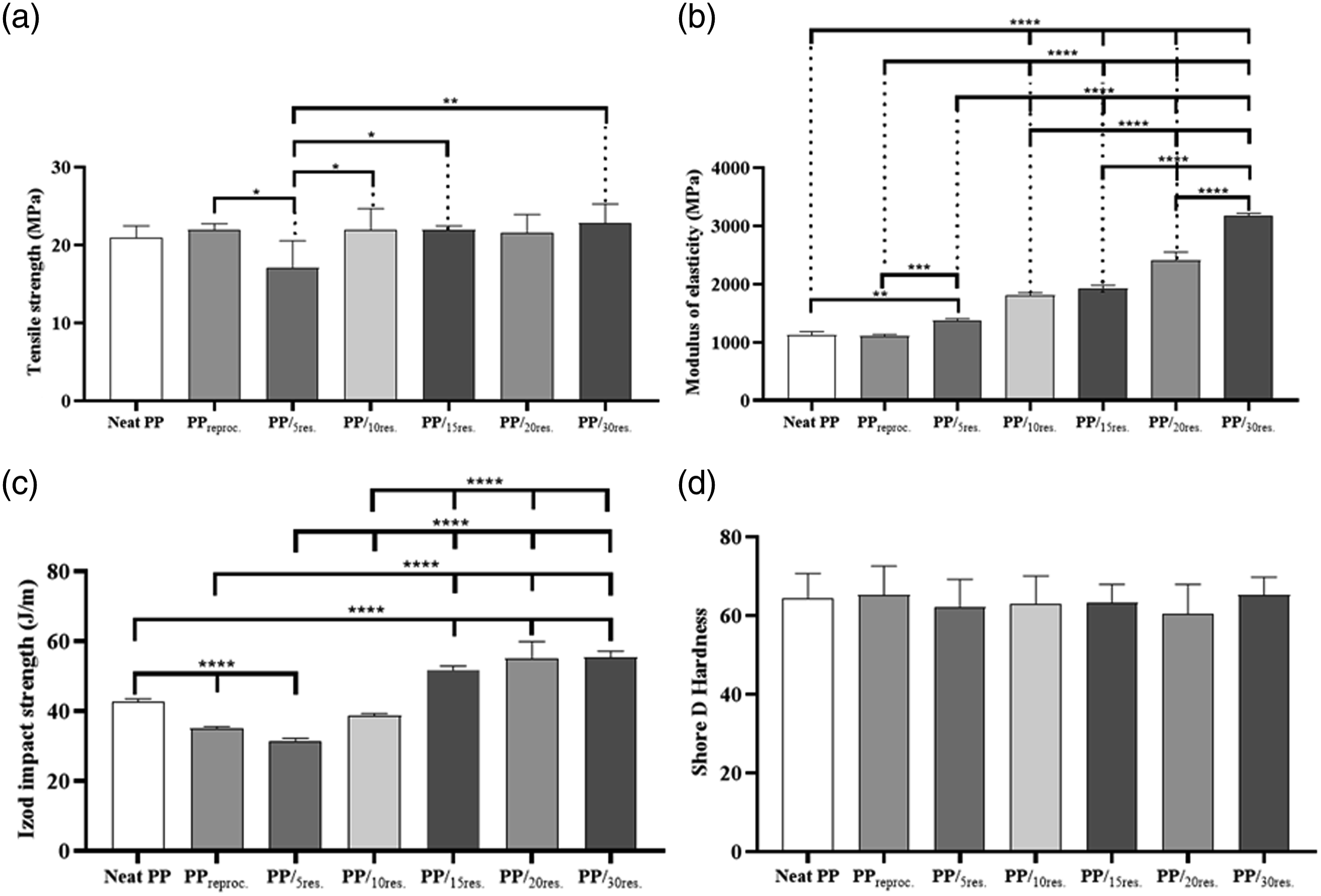
Graphs with the statistic values of the tensile strength (a), elastic modulus (b), Izod impact strength (IS) (c), and Shore D hardness (d) for all the samples. Results are given as mean ± SD (n = 5, n = 5, n = 5, n = 9, respectively). Asterisks indicate statistical significance: *p < 0.1, **p < 0.01, ***p < 0.001, and ****p < 0.0001 (ANOVA/Tukey’s multiple comparison).
PPreproc. and the PP/5res. the composite showed a decrease of 10% and 22%, respectively, in UTS values, being statistically significant compared with neat PP (Figure 7(a)). As the filler contents in the PP matrix increased, the UTS values were less expressive. It can be considered that the tensile strength of the other composites (PP/10res., PP/15res., PP/20res., and PP/30res.) developed remained close to neat PP (Figure 7(a)), indicating a good transfer of stresses from the matrix to the reinforcement, since it is known that the tensile strength of polymer composites vary according to the content, aspect ratio, and hardness of the filler particle used, tending to reduce the tensile strength of polymers with the increase of the filler, mainly for values greater than 30 wt% of filler that can generate the formation of large agglomerates. Thus, Kismet, Dogan, and Wagner 15 studied the influence of three different electrostatic powder coating wastes of thermoset structure on the LDPE matrix. The authors observed a decrease in the tensile strength of the LDPE composites with the different fillers, being less pronounced in the samples filled with epoxy powder residues, as they are harder than the other two fillers (epoxy/polyester and polyurethane). According to the authors, this behavior may have led to a more homogeneous mixing between the LDPE and the epoxy filler and a decrease in the air spaces between the particles and the matrix, thus improving the physical bonding mechanism between the filler and the epoxy filler.
Regarding the elastic modulus results, a statistically significant increase was observed for all composites compared to neat PP (Figure 7(b)), showing an increase in the stiffness of the developed composites. This fact may be related to the increase in the percentage of particles added to the PP matrix, which may have restricted the mobility of the PP chains, and thus, reflected in the increase in the values of E, that is, the presence of fillers in the matrix of PP reinforced the rigidity of the materials.
In the IS results, it was observed that the PPreproc. showed a decrease of 22% in IS values when compared to neat PP. However, when adding 5 wt% of filler in the PP matrix, the IS value practically remained; however, the increase of filler content in the PP matrix caused a strong improvement in impact resistance up to the limit of the addition of 20 wt% (PP/20res.), because with the addition of the highest filler content, 30 wt% (PP/30res.), a decrease of 4.5% was observed when compared to the PP/20res. composite (Figure 7(c)).
Shore D hardness values of neat PP, PPreproc., and the composites do not differ from a statistical point of view (Figure 7(d)). Since this is a surface measurement, the surface of polymeric composites is naturally richer in the matrix than the average added filler.
Figure 8 shows SEM micrographs of the cryofractureted surfaces of neat PP, PPreproc., PP/5res., PP/10res., PP/15res., PP/20res., and PP/30res. composites. In Figure 8(a) and (b) it is possible to verify the morphological surface of the neat PP and PPreproc. samples, respectively. In both images, it is possible to observe a heterophasic material. Since this PP is a copolymer formed from propylene and ethylene, probably synthesized as a block. These blocks segregate in the matrix as they are immiscible, resulting in a softer second phase, observed as cavities (highlighted in red in Figure 8(a)–(e)). This strategy seeks a toughening of the PP copolymer about the PP homopolymer directly in the synthesis of the material. SEM micrographs of the cryogenic fracture: neat PP (a), PPreproc., (b), PP/5res. (c), PP/10res. (d), PP/15res. (e), PP/20res. (f), and PP/30res. (g).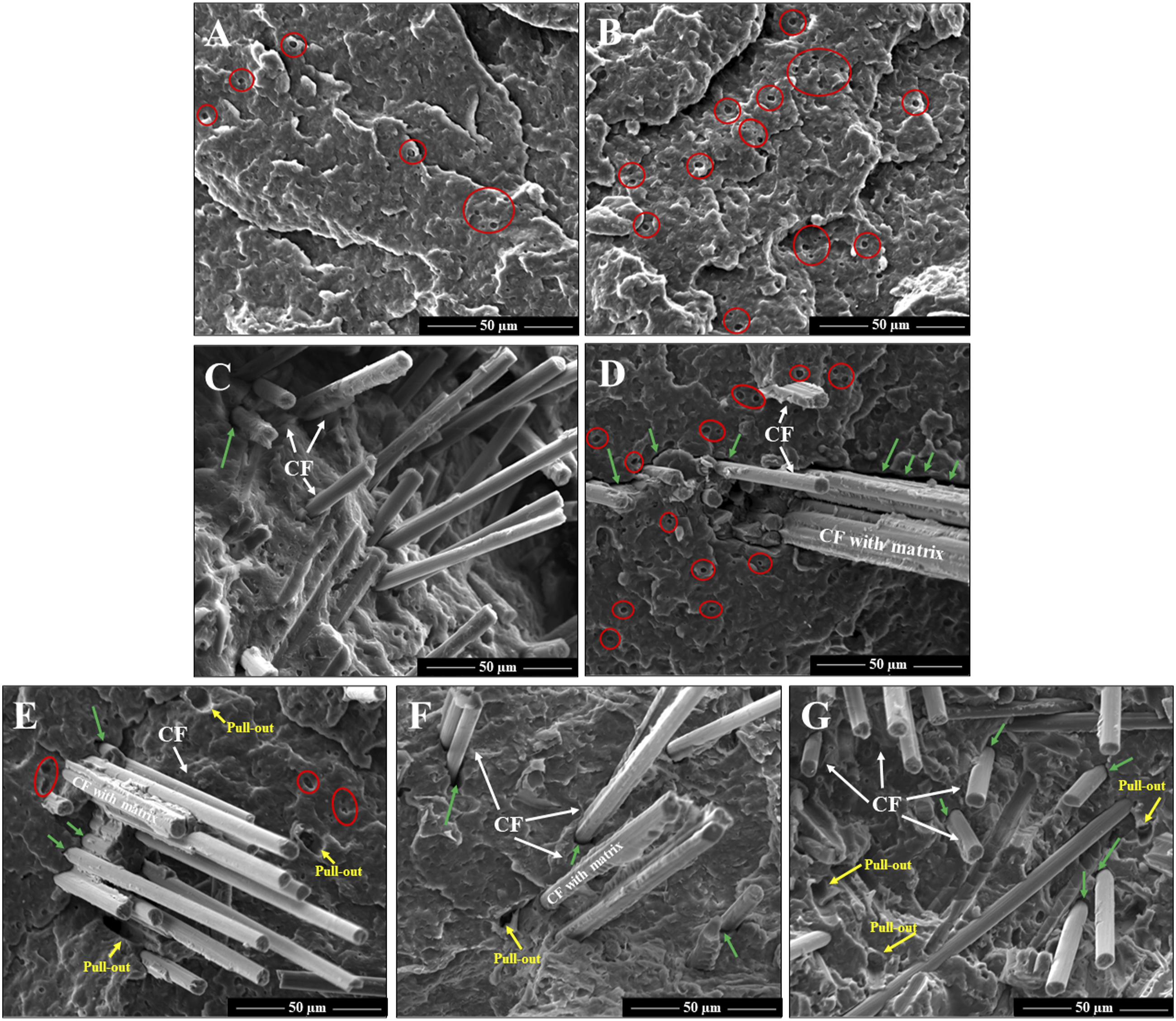
Regarding the morphological surface of the PP/CFRPres composites (Figure 8(c)–(g)), it is possible to observe the extent of the cryogenic fracture surface analyzed the presence of some gaps (holes) between the particles and the PP matrix (highlighted in green in Figure 8(c)–(g)) from their detachment, which may be due to the low interfacial adhesion and low wettability of the particles inside the PP matrix. This behavior was already expected since no compatibilizer agent was used. However, in some regions on the analyzed surface, it is possible to verify that there was a good load transfer to the reinforcement through the presence of a matrix adhered to the CF surface, which corroborates the values obtained for the mechanical properties (Table 2 and Figure 7). In addition, in the micrographs of Figure 8(e)–(g) it is possible to observe the presence of pulled-out indicating that the CF was removed from the PP matrix (highlighted in yellow in the micrographs). The presence of several regions with pull-out may be related to a large number of short fibers, resulting from the milling process since ground particles were added. These particles are CF-reinforced epoxy composites, which after milling, resulted in particulate composites composed of very small CF, and which consequently do not have strong adhesion with the polymeric matrix, being easily pulled out or detached resulting in pull-out. A large number of voids is indeed the result of the homogenization process of thermosetting composite waste with the PP matrix.
Furthermore, as the proportion of CF/epoxy particles was added to the PP matrix, consequently, their concentration in the matrix increased, causing this filler to be very close to each other, reflecting the improvement in the mechanical properties as well as can contribute to the formation of a conductive path, which can lead to improvements in electrical properties.
The AC electrical behavior obtained by impedance spectroscopy is presented in Figure 9, in terms of the electrical conductivity and the relative permittivity. For the PP/CFRPres composites, on the one hand, the PP matrix presented a high insulative behavior with a low electrical conductivity which was frequency dependent, which was observed for the neat PP and PPreproc.
31
On the other hand, the CFRP possesses a semiconductive behavior due to a combination of the high electrical conductivity of the carbon fibers and the insulative behavior of the epoxy resin matrix.32,33 As a result, the AC electrical conductivity increased proportionally for most of the composites, with a curve shifting up to 20 wt% of CFRP residue. For the higher CFRP content, PP/30res. composite, the electrical behavior drastically changed to a semiconductive behavior with constant AC conductivity values around (10−3 S/cm). That behavior indicates that PP/30res. might have many electrical paths of CF formatted, being above the electrical percolation threshold, observations that corroborate with the morphological analysis. Electrical conductive PP composites, such as PP/30res., may be interesting for antistatic packing applications.
34
Impedance spectroscopy results: AC total volumetric conductivity (a) and relative electrical permittivity (εr) (b).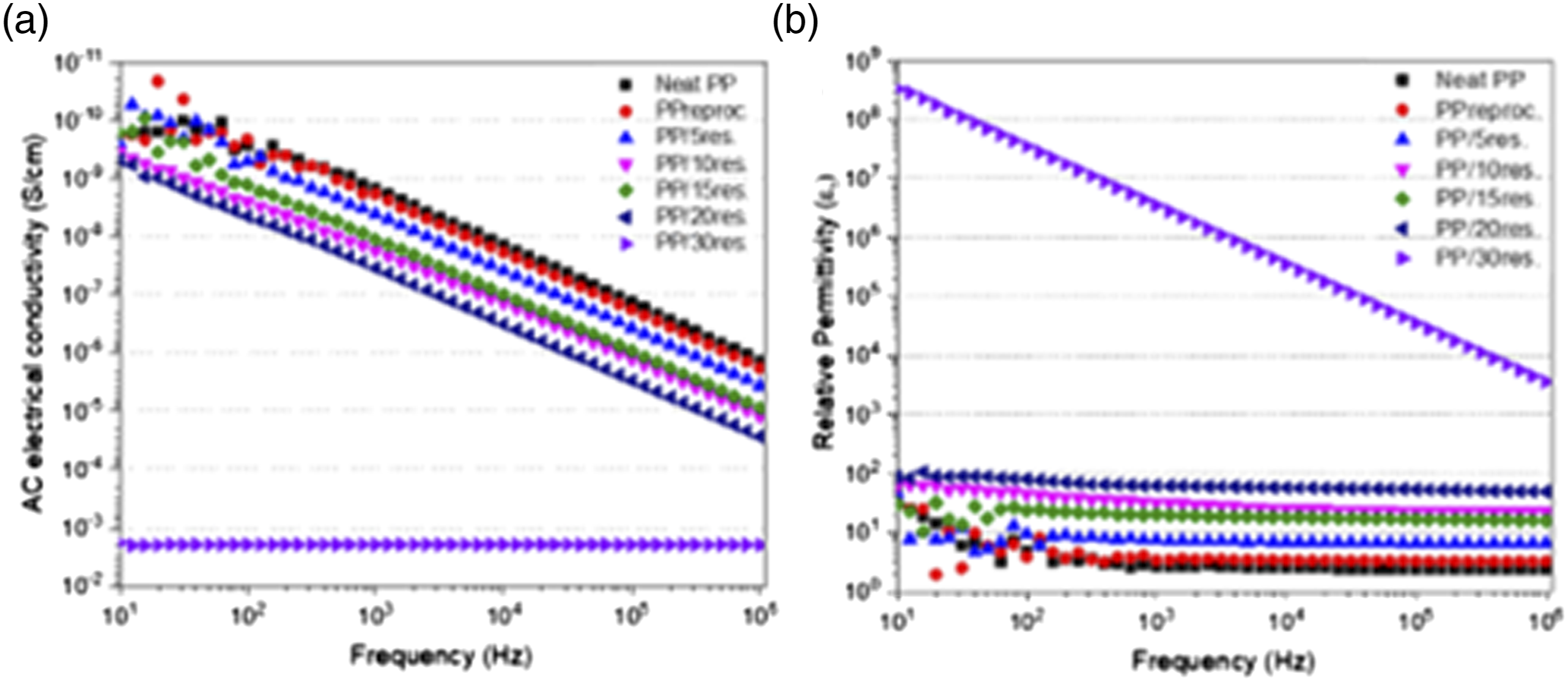
An analogous behavior of the AC conductivity was observed for the relative permittivity (εr) values, which had also increased with CFRP content. However, insulative samples have almost linear permittivity for those values, while highly conductive samples had a frequency-dependent behavior. The εr of material could be related to the interactions of the material with the electric field applied through diverse phenomena, such as interfacial polarization, dipolar polarization, omics losses, etc. 35 The reason for the weak frequency dependencies of the complex permittivity of composites is their insulating nature, whereas the strong frequency dependencies originate from the significant enhancements in the electrical conductivity exhibited by the composite. 36 All those phenomena might be potentialized for higher CFRP residue content via highly conductive filler addition. Therefore, the elevated εr values observed are desirable for materials applied to electromagnetic shielding (EMI) applications.
Figure 10 shows the relative permeability (μr), relative (εr), real (ε′), and imaginary (ε'') permittivity for all the samples under study. Knowing the permittivity and permeability values are extremely important for developing absorber materials, which can be used for the production of electronics housings, and in the automotive sector for wire and cable protection. Values of μr (a), εr (b), ε' (c), and ε'' (d) as a function of frequency for the neat PP and PP/CFRPres composites.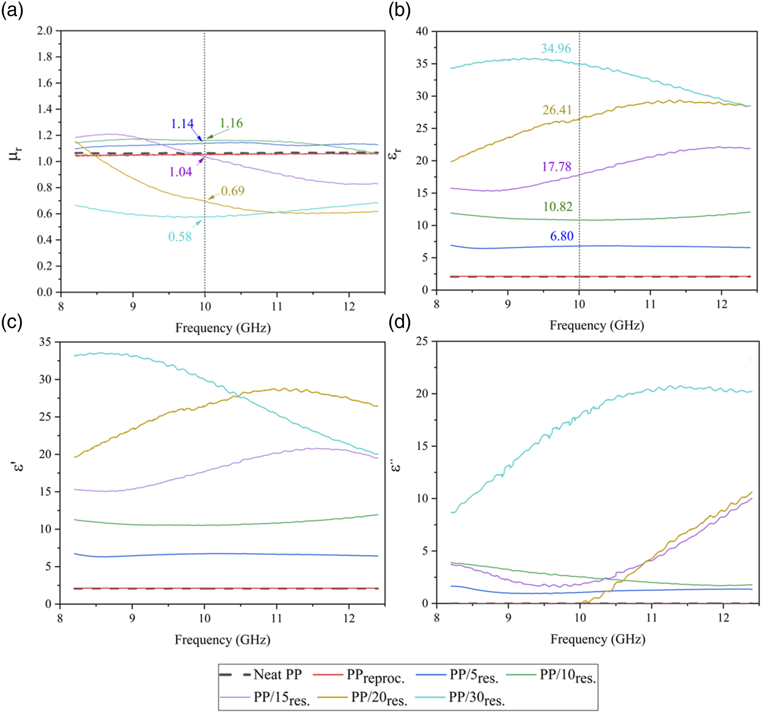
As shown in Figure 10(a) and (b), the neat PP, and PPreproc. samples showed similar results for μr and εr, around 1 and 2.4, respectively; these values of the complex parameters indicate that the materials are insulators. With this, the values μr and εr are constant in the entire frequency range of the X-band. This means that the reprocessing did not interfere with the electrical and magnetic properties of the material, these properties being permittivity and permeability, respectively. It is important to emphasize that the real part is associated with the stored energy, and the imaginary part represents the energy losses.
Figure 10(c) and (d) shows that the real and imaginary permittivity values of the samples with higher CFRP content (PP/15res., PP/20res., PP/30res.) varied with frequency. However, the samples did not behave analogously, the ε′ of PP/30res. decreases with frequency, the opposite occurs for PP/15res., PP/20res. where ε′ increases with frequency. Furthermore, the εr gradually increased with CFRP addition in PP, resulting in 6.80, 10.82, 17.78, 26.41, and 34.96 for PP/5res., PP/10res., PP/15res., PP/20res., and PP/30res., respectively, at the 10 GHz frequency. It was expected because the permittivity is influenced by the electrical conductivity. 37 This result corroborates the impedance spectroscopy (Figure 9). On the other hand, the μr decreased with CFRP content, showing values of 1.14, 1.16, 1.04, 0.69, and 0.58 for PP/5res., PP/10res., PP/15res., PP/20res., and PP/30res., respectively, in 10 GHz.
The εr values were significantly higher when compared to μr, indicating that the absorption phenomenon occurs through dielectric losses. The results showed that these materials are suitable for EMI applications.
According to the literature, many researchers have studied the application of carbon fiber in polymer composite, showing promising results for electromagnetic shielding. Ameli et al., 38 studied solid and foamed CF/PP composites with various CF contents, the EMI shielding effectiveness of the CF/PP composites increased with increasing CF. Hwang 39 produced solid and foamed poly butylene terephthalate/carbon fiber composites; electrical conductivity increased when the fiber content increased . Liu et al., 40 produced CF/PP composites, with 20% FC by mass, obtained excellent EMI SE results of 30.8 dB . Furthermore, it showed that carbon fiber less than 13 wt% has no EMI effectiveness. The disadvantage of CF is the high cost, being an alternative to recycle CF. However, it has few studies and as shown in this study, this area seems to be very promising.
Conclusions
This work aimed to reuse thermoset composite residue from the aerospace sector as an alternative raw material for developing new products that can return to the industrial production process of various sectors as a substitute material for thermoplastic matrices, increasing their mechanical and electrical properties, aiming at cost reduction combined with sustainable development.
The methodology used in this project, from the collection, separation, grinding of the composite wastes, granulometric separation, processing and homogenization with neat PP, and obtaining standardized test specimens, proved to be satisfactory.
The presence of residues in particles form did not change the thermal stability of the composites since the melting temperature of the PP/CFRPres composites was not changed significantly with the increase of particle content; however, these particles acted with nucleating agents in the PP matrix, resulting in an increase in the crystallinity degree as the CFRP residue particles content in the polymer matrix increased.
SEM micrographs of cryofractured surfaces revealed the presence of some gaps (holes) between the CFRPres particles and the PP matrix due to poor interfacial adhesion, due to the absence of the use of compatibilizing agents, and low wettability of the particles inside the PP matrix. However, in some analyzed regions it is possible to verify that there was a good load transfer to the matrix, corroborating the values obtained for the mechanical properties.
Electrical conductivity measurements showed that the PP/CFRPres composite with the addition of 30 wt% of CFRPres. increases the electrical conductivity by seven orders of magnitude compared to neat PP and exhibits semiconductor behavior. As for the electromagnetic properties, increasing the content of residues in the composites also occurs a substantial increase in the relative permittivity. The PP/30res.composite showed the best performance, resulting in a relative permittivity of 34.96 at 10 GHz in the X-band.
Thus, through these studies, it was possible to aim at sustainable development and protection of the environment, through the reuse of thermoset residue, with high added value that could return to the production process of the automotive sector, antistatic packing, or for the production of electronics housings, which are applications that demand specific mechanical, electrical, and electromagnetic properties with a residue that would be destined for incineration and/or the landfill. These results are very promising for the development of future components, and they can return to the life cycle with high added value, in addition to contributing to sustainable development and preservation of the environment and renewable resources.
Footnotes
Acknowledgements
The authors would like to thank Prof. Dra. Mirabel Cerqueira Rezende from the Federal University of São Paulo (UNIFESP) and Sergio Mayer for the donation of CF/epoxy composites that were used in this work. The authors are grateful to FAPESP (Fundação de Amparo à Pesquisa do Estado de São Paulo, process 2020/12501-8) and CNPq (Conselho Nacional de Desenvolvimento Científico e Tecnológico, processes 440132/2021-3 and 307933/2021-0) for financial support.
Declaration of conflicting interests
The author(s) declared no potential conflicts of interest with respect to the research, authorship, and/or publication of this article.
Funding
The author(s) received no financial support for the research, authorship, and/or publication of this article.