
Abstract
This paper discusses and analyses a compliant centrifugal clutch with different materials. Compliant centrifugal clutch specimens required for investigation are prepared by an injection moulding process. Experiments are conducted based on the experiments designed as per Taguchi’s Design of Experiment (DoE); an L27 Orthogonal Array (OA) is formulated and a multi-response optimisation approach Technique of Order Preference Similarity to the Ideal Solution (TOPSIS) is adopted for optimising torque carrying capacity, wear rate and, contact temperature. Experiments are conducted for three different polymer materials viz., polypropylene (PP), Delrin (DE) and polyurethane (PU) with three different profiles, circular (CR), elliptical (EL) and square fillet (SF), along with varying rotating speeds. The outcome shows that by changing the clutch material and flexure profiles, a substantial variation in torque carrying capacity, wear rate and contact temperature is observed.
Keywords
Introduction
A compliant mechanism transmits motion and force through the deformation of an elastic body using a flexible link; these structures may be monolithic (made of a single component) or have no joints. Backpack latches, nail clippers, and paper clips are examples of everyday gadgets that use compliant mechanisms. 1 A compliant link has a single or combination of various segments, including rigid ones. Fully compliant mechanisms are flexible without rigid links that can only move when their flexible components are deflected. Partially compliant mechanisms are those in which some movements are made possible by the joints of stiff bodies. 2 Compliant mechanisms exhibit advantages such as reduced assembly time and cost, monolithic or lower part numbers, reduced/no lubrication requirements, enhanced mechanical accuracy and dependability, manufacturability and ergonomics, less wear, lash, shock and noise and parts miniaturisation.
Furthermore, considerable deflections are involved with compliant mechanisms.
3
These deflections are highly nonlinear and complicate design and analysis efforts. Additionally, electronics made of polymers frequently exhibit reduced fatigue and creep resistance. Centrifugal clutches work on the principle of centrifugal force. The benefits of centrifugal clutches include simple design and working, engaging automatically at a predetermined speed, dampening shock loads and reducing startup loads on internal combustion engines and A.C. motors.
4
The acceleration of a rotating body about a centre has two components: normal or centripetal and tangential, as shown in Figure 1. A body revolving at a constant speed is seen in Figure 1(a). The motion equations are shown in Figure 1(b) using Newton’s second law in conventional form. The motion equations employing D’Alembert’s principle and centrifugal forces are displayed in Figure 1(c).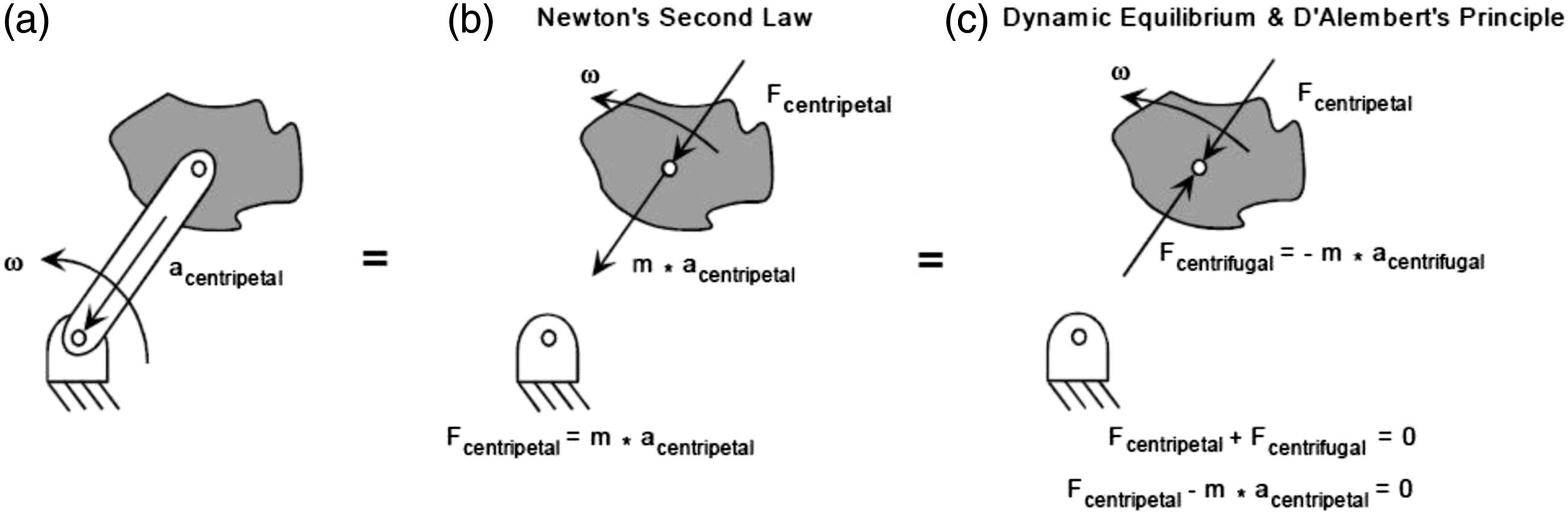
Crane et al. 7 investigated a floating-opposing-arm (FOA) centrifugal clutch with a configuration of contact surfaces that are non-aggressive and aggressive with the contact pairs. They found that the PRBM FOA centrifugal clutch had superior starting smoothness and stability than the previous one. Akano and Fakinlede 8 proposed a continuum damage mechanics (CDM) prototype for calculating the fatigue lifespan of compliant mechanisms from polymers considering varying stress cycles. Experimental and simulation results revealed that low-density polypropylene (PP) is suitable for compliant mechanisms within the compressive region. The observational results and numerical simulations correspond well with the conceptual forecasting formula’s statistical analysis. Abdullah and Schlattmann 9 used the finite element approach to analyse the contact analysis of a dry friction clutch system during their engagement. The diaphragm spring’s contact pressure and the centrifugal force were used as the load conditions. According to the results, contact pressure and penetration are at their highest and lowest points, correspondingly around the outer and inner disc radii.
Tran et al. 10 created a novel hybrid computational approach for solving Scott Russell-compliant mechanisms by combining the desirability function methodology, LAPO algorithm, fuzzy logic, and artificial neuro-fuzzy models. Results show that the suggested hybrid methodology’s prediction accuracy is better than conventional Taguchi-based fuzzy logic. Tran et al. 11 provided the compliant mechanism of 2-DoF fatigue life; A-36 and Al 6061-T6 materials were chosen for investigation. The outcomes from these two studies involving the materials steel A-36 and aluminium 6061-T6 indicated that the precision was extremely high, with a significance level ranging from 0.05 to 0.1. An adaptive neuro-fuzzy inference system (ANFIS) and differential evolution with subtractive clustering were used. Taking into account the binding among the materials, the capacity of the pivot to transmit the necessary loads with the stipulated degree(s) of freedom and adding process-specific needs throughout the design phase, Bejgerowski et al. 12 investigated a novel method for designing and fabricating small hinges in compliant mechanism made of multiple materials for an efficient and compact design of the micro-air vehicle drive mechanism where multi-material compliant mechanism resulted in a reduced number of parts in the drive assembly by eliminating several rigid bodies articulating joint. The correlation of interface temperature and the wear rate (WR) at the contact point between the specimen and tool was studied, and it reported that, as interface temperature increases, the rate of wear tends to increase. 13
Gouker et al. 14 have introduced multi-material moulding that describes many kinds of functional articulations in compliant mechanisms. Compliant joints can be utilised to decrease the number of parts and do away with assembly processes, according to the investigation. More complicated structures can be created at lower costs by using multi-material moulding. Howell and Midha 15 provided an approach to help design compliant mechanisms with short flexible pivots compared with moderately stiff sections. The technique used a large-deflection finite element type approach and a pseudo-rigid body model. The design methodology developed and described in this inquiry worked well for designing compliant mechanisms and offered an alternative to the industry-standard trial-and-error techniques. A compliant segment motion generation method with a flexible segment coupler was first presented by Saggere and Kota. 16 They provided a methodical process for synthesising single-loop compliant mechanisms without moving stiff connections to generate compliant segment motion. A loop-closure equation was employed to create rigid linkages connecting the flexible segments, which was then combined with the elastic equilibrium equation in an optimisation technique.
A thorough examination of the tribological action of polymeric composites, as impacted by distance of sliding, velocity, temperature and pressure applied was carried out. The impact of fibre content, shape, and alignment on tribological performance was also discussed. The most common causes of failure include debonding of fibers from matrix, delamination, erosive, corrosive, and abrasive wear. 17 The poly-ether-ether ketone (PEEK)-MWCNTs performance during wear studies, manufactured using the melt mixing approach was investigated, and it was discovered that the specific rate of wear falls under severe dry sliding circumstances due to the creation of a transfer coating on the steel disc. In comparison to PEEK, the introduction of MWCNT to the PEEK matrix yielded better wear resilience. The majority of the worn samples’ substrates had plastic deformation and micro-abrasion. MWCNTs reduced the COF and increased resistance towards wear. 18 Taguchi’s orthogonal layout and grey assessment were used to optimise turning PEEK-30% carbon fibres with TiN-coated tools for simultaneous decrease of forces generated and roughness produced. The feed rate was the largest relevant parameter studied, closely by depth of cut, and the connection amongst the components also had an influence on the grey grade. Among the levels analysed, multiobjective optimization strategies yield superior outcomes. 19
Zhang and Chen 20 offered a thorough approach to the problem of large deflection based on the elliptic integrals and found that PRBM is used to evaluate compliant mechanisms. A compliant connection is renovated with metallic inserts following the PRBM stress equations. The results of the experimental tests for stress relaxation, creep and fatigue are shown, demonstrating the performance improvement offered by metallic inserts. Lobontiu et al. 21 developed mathematical compliance models for flexible hinges made from conic-section (parabolic, elliptic, circular, and hyperbolic). The findings evaluated the rotational correctness of a specific conic flexure pivot and projected the region of deformation/displacement under different loads. Conclusions supported the theoretical formulation data and the finite element simulation results. The considered conic flexural pivots are better compliant than a circular for a higher length ratio to thickness. Henning et al. 22 considered a nonlinear method of modelling different notch pivots considering rotation in in-plane position and executed a design procedure that employs theory for significant deflections of rod-like structures. Elliptical, power function, corner-filleted, and circular pivot profiles were the four selected and included in the design tool. Without the requirement for repeated and time-devouring simulations, the given design tool helped to accelerate a quasi-static investigation of the elastic-kinematic characteristics of notch flexure hinges. Senthilkumar and Tamizharasan 23 considered different geometries of the tool and identified the correlation between the wear of the tool and the measured interface temperature. An infrared thermometer gun measured the temperature at the interface; increasing contact temperature increases wear due to softening material at the interfaces.
From the literature, it was found that limited work was reported on pseudo-rigid bodies as centrifugal clutch performance evaluation using different polymeric clutch materials and clutch profiles. Contact temperature analysis between the clutch hub and centrifugal clutch measurement is essential, which decides the wear of clutch material and torque carrying capacity; works related to this are also very much limited. Based on the identified gap, objectives are derived and achieved. The novelty of the present study is the utilisation of three different polymeric materials, viz., polypropylene, Delrin and polyurethane and considering three different profiles, cylindrical, elliptical and square profiles as pseudo-rigid body centrifugal clutch. Also, analytical and experimental contact temperature and torque carrying capacity are compared. Experiments are designed based on Taguchi’s design. The outputs are optimised using a multi-objective optimisation approach to identify the ideal material with the best flexure profile for a compliant centrifugal clutch. The manuscript consists of an introduction section dealing with the introduction of the pseudo-rigid body mechanism and related studies by previous researchers. Materials and methods comprises the materials for the centrifugal clutch and the experimental methodology. The results and discussion about the obtained outputs are detailed in section 3, and the conclusion is derived in section 4.
Materials and methods
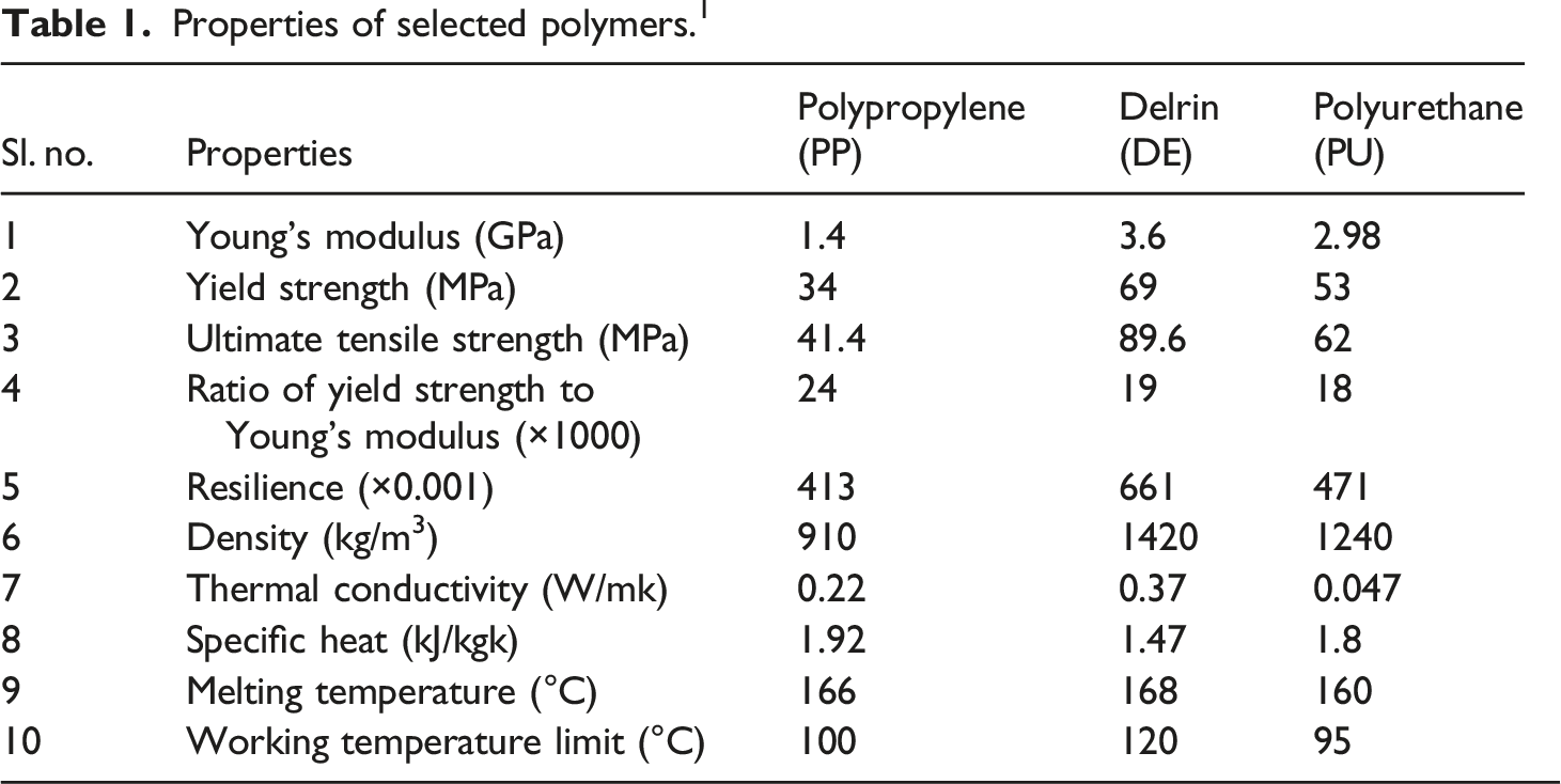
Properties of selected polymers. 1
Polypropylene
Because of its greater yield strength to Young’s modulus ratio, polypropylene is an excellent material for making compliant mechanisms. The advantages of polypropylene are: inexpensive and readily obtainable. Because of its semi-crystalline structure, it has excellent flexural strength, resistance to moisture absorption, good chemical resistance, fatigue resistance, impact toughness strength and electrical insulator. 27 The limitations of polypropylene are it cannot be used in high-temperature applications owing to its higher thermal expansion coefficient and is highly inflammable and vulnerable to oxidation and UV degradation. Numerous packaging applications employ it because of its high strength, excellent surface finish, and affordable price. Toys, furniture, home goods, and other consumer goods are among the items that employ it. Due to its better mechanical properties, it is used in automotive parts like bumpers, battery cases and interior trim. Its high chemical and bacterial resistance it is primarily used in medical applications. 28
Delrin
Delrin is a good choice for compliant segments and compliant mechanisms. Delrin possesses high yield strength and rigidity, high impact toughness strength, better resistance to creep and resilience, outstanding resistance to natural chemicals, solvents, moisture and gasoline, excellent dimensional stability, suitable self-lubricating property and high electrical resistance. Delrin is primarily used in automotive applications, seatbelt, control switches, loudspeaker grills, and windows. 29 Many industrial types of equipment are made of Delrin, gas meters, pumps and beverage valves, farm machinery, hose couplings, spur and helical gears, bevel and worm gears, and pump impellers. Most consumer goods and appliances are made of Delrin, including clips, toys, knife handles, rollers and chair coaters, zippers, a variety of pen components, garage door openers etc. 30
Polyurethane
Polyurethane has more flexibility. Compliant links and compliant mechanisms are made of polyurethane with metallic inserts. Polyurethane possesses high tensile strength, good abrasion and oil resistance, good chemical resistance, and better processability and toughness. 31 The products made of polyurethane are oil seals, forklift truck tires, and shoe heels.
Pseudo-rigid-body model
Pseudo-Rigid-Body Model (PRBM) is an approach for distinguishing compliant mechanisms by estimating individual member deflections by Howell in 2001. By substituting the compliant segment with a rigid body analogue and establishing a pivot point, referred to as a typical pivot, within the two-rigid links, the PRBM technique can be utilised to simulate the tip deflection of the compliant segment. 32 The length of the rigid segments added together equals the primitive compliant link length, and the position of the distinctive pivot calculates the length equivalent to the individual link. Selection of material, synthesis and analysis kinematically are challenging aspects of designing compliant mechanisms because of their nonlinear nature. The PRBM are a method for analysing significant deflection issues. 33 Previous researchers created the PRBM concept to help construct the compliant mechanism. By substituting the compliant segment with a kinematic similarity created by identifying a hinge (pivot) point, mentioned as a characteristic hinge (pivot), inside the two rigid links, the PRBM technique is utilised to simulate the compliant segment’s tip deflection. The characteristic hinge (pivot) is located by superimposing two rigid links, and the length of the original compliant link is calculated by adding two rigid link segments. 34
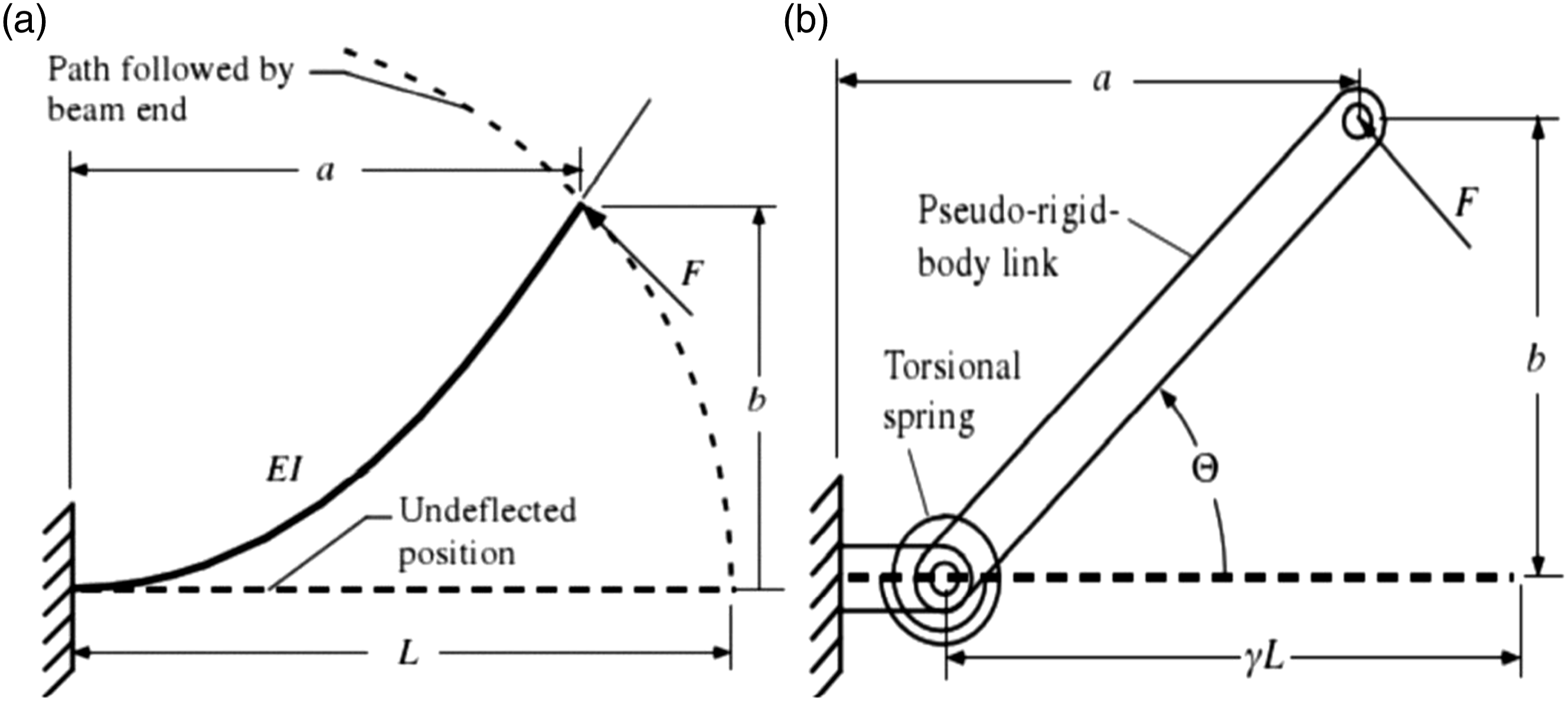
Figure 2(a) depicts a fixed free beam with force at one end. According to this model, the beam’s curvature is least at the free end and most significant at the fixed end. Figure 2(b) illustrates how a PRBM can simulate the motion of the beam by substituting a rigid link pinned to a fixed link for the flexible beam. The fixed link’s length is set between 0.15 L and 0.17 L, and the pseudo-rigid link’s length is set between 0.83 L and 0.85 L while the pseudo-rigid beam is under load and rotates through an angle of ‘ʘ’. (a) Compliant beam fixed free with free end force (b) Equivalent PRBM.
14
The following steps are involved in synthesising the compliant centrifugal clutch, 1. Rigid body connected centrifugal shoe clutch as shown in Figure 3(a) is identified for rigid body replacement synthesis, in which there are 13 parts with optional spring locations. 2. Flexure hinges in the connected shoe centrifugal clutch replace the springs. The flexure hinges accurately capture the function of the spring. 3. The connected shoe centrifugal clutch is converted into a monolithic (single piece) compliant centrifugal clutch with different profiles, which are shown in Figure 3(b)–(d). 4. A compliant centrifugal clutch with different profiles is developed, and the dimensions are shown in Table 2. Rigid body centrifugal clutches. Compliant centrifugal clutch parameters.
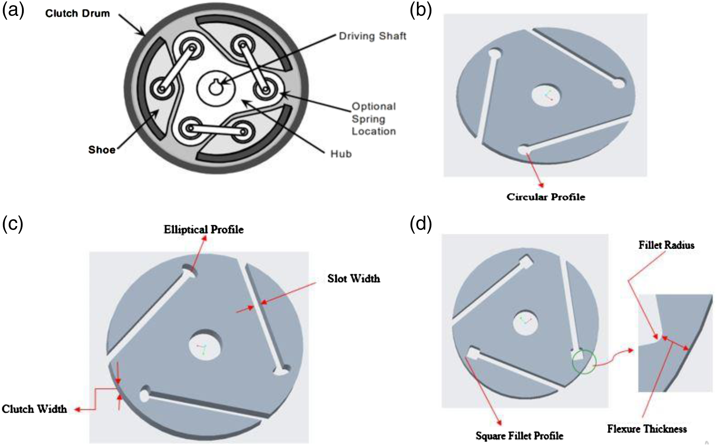
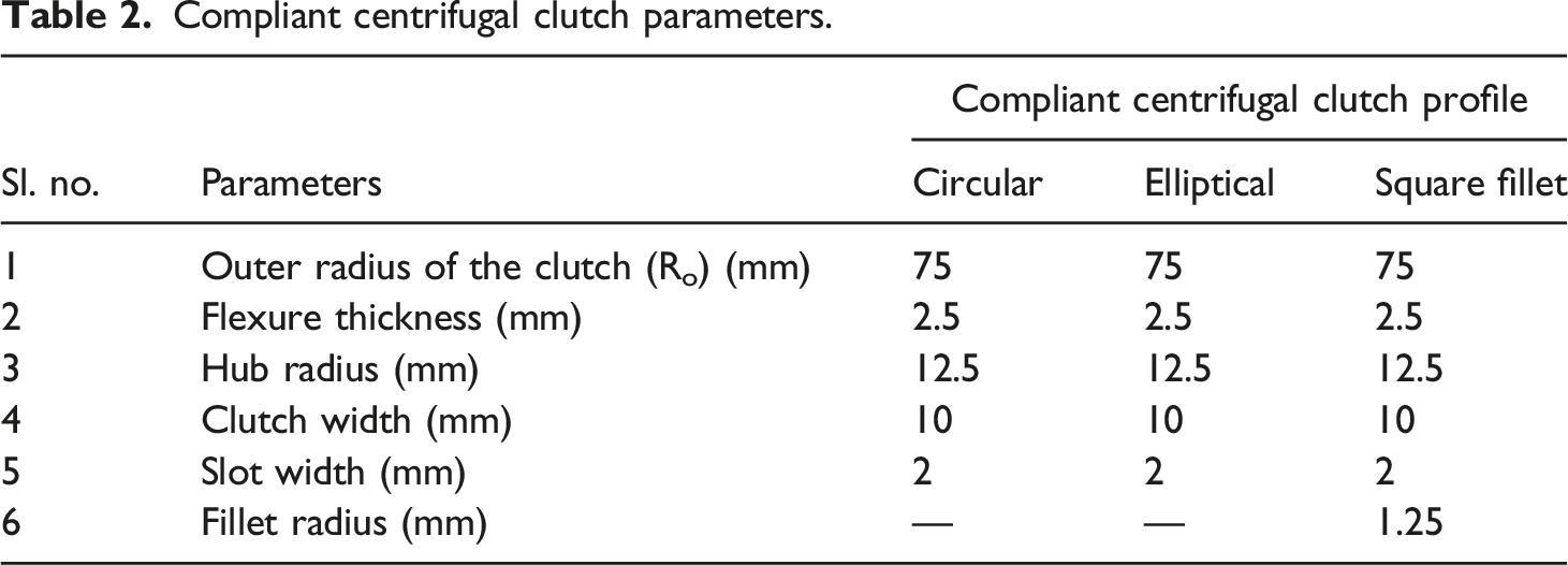
Figure 3(a) presents the rigid kinematic body connected centrifugal shoe clutch with 13 parts, Figure 3(b) presents a single-piece compliant centrifugal clutch with a circular profile, Figure 3(c) presents a single-piece compliant centrifugal clutch with a circular profile, and Figure 3(d) presents a single piece compliant centrifugal clutch with square fillet (SF) profile.
After selecting appropriate materials, a compliant centrifugal clutch is fabricated per the required dimensions and geometry and tested to meet the requirement. The main objective of this research is to develop cost-effective compliant centrifugal clutches without compromising performance and a novel compliant double wishbone suspension system. Centrifugal clutches are utilized in lawn and garden trimmers and power hacksaws. Higher clutch diameter and thickness will be an ideal choice for higher torque requirements.
Taguchi’s experimental design

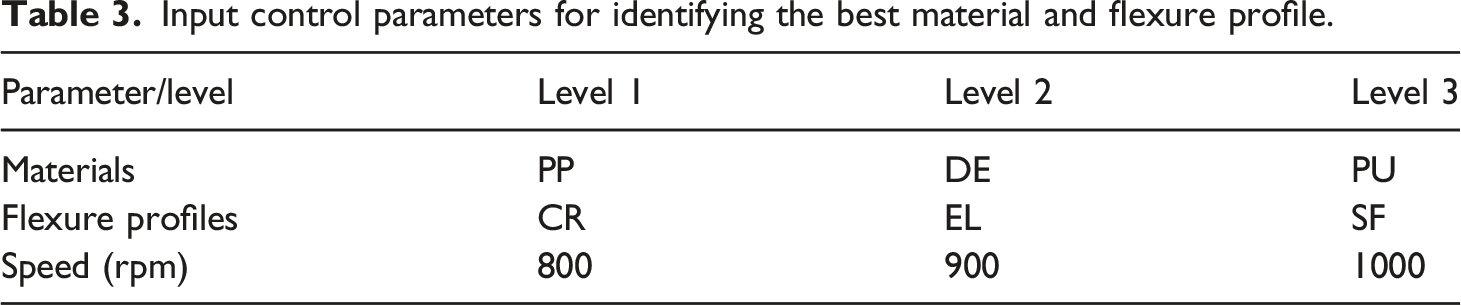
Input control parameters for identifying the best material and flexure profile.
Technique for order of preference by similarity to ideal solution
The Technique for Order of Preference by Similarity to Ideal Solution (TOPSIS) approach was created on the premise that the ideal alternative should be the furthest away from a matching negative-ideal solution while still being the closest to the ideal solution.
41
Both hypothetical positive and negative answers are calculated using the technique. The TOPSIS method was improved due to the concept of relative closeness determination. Finding the “ideal” solution, which is made up of better attribute values achievable, and the “negative-ideal” solution, which is made up of worst possible attribute values, is simple when it is assumed that individual attribute decreases or increases monotonically utility.
42
One strategy is to choose an option that, geometrically speaking, is closest to the ideal solution by the (weighted) minimum Euclidean distance.
43
The decision matrix, which has ‘m’ choices and ‘n’ attributes, is evaluated using the TOPSIS method (or criteria). The procedures used to put TOPSIS’ methodology into practice are as follows: a. The TOPSIS technique evaluates a decision matrix with ‘m’ choices linked to ‘n’ attributes (or criteria) as follows: b. Create a decision matrix normalized by converting different attribute dimensions into non-dimensional values for comparison. c. To produce the weighted normalized evaluation matrix, multiply every matrix column by the appropriate weight. d. Select the ideal and negative-ideal solutions, with A* and A−denoting the ideal and negative-ideal solutions, respectively, as the most and least preferable options. e. Determine the n-dimensional Euclidean distance used to measure the distance between each choice. f. Determine the Relative Closeness Coefficient (RCC) to the ideal solution; an alternate solution Ai is near A* as RCCi* becomes closer to 1. g. Sort the preferences following the descending order of RCCi*.
Fabrication of compliant centrifugal clutch
Using computer-aided design software Creo Parametric, 3D models of the compliant centrifugal clutch with ‘different profiles are developed, is shown in Figure 3(b)–(d). After modeling, a high-carbon steel mould is prepared using a CNC milling machine, which is used for fabricating the compliant centrifugal clutch prototypes. The injection temperature and injection pressure in injection moulding is maintained at 180°C and 80 bar for Polypropylene (PP) and 200°C and 100 bar for Delrin (DE), whereas for Polyurethane (PU), the injection temperature and injection pressure maintained is 120°C and 80 bar respectively. The injection speed and filling time in injection moulding are maintained at 20 g/sec and 5 seconds for polypropylene and 8 g/sec and 10 seconds for Delrin, whereas for polyurethane, the injection speed and filling time maintained is 15 g/sec and 8 sec., respectively.
Experimental setup for testing
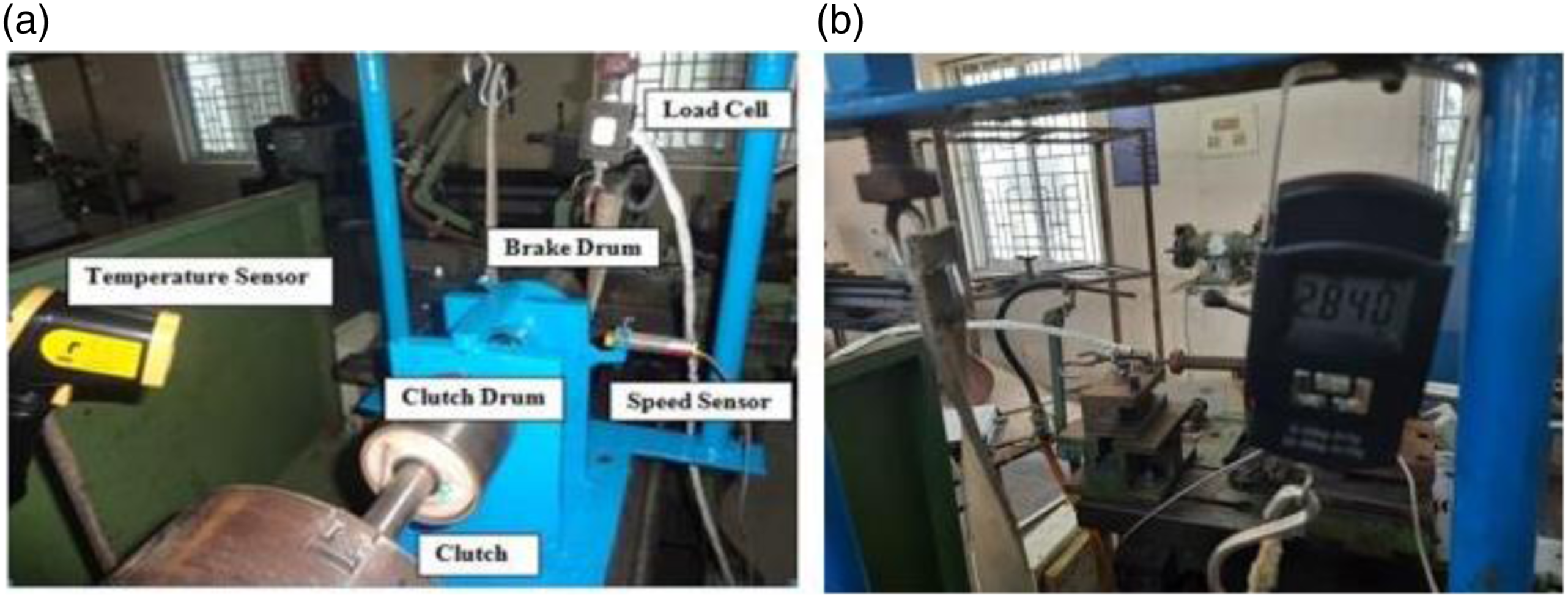
An experimental test rig is built to measure the torque-carrying capacity and contact temperature of the compliant centrifugal clutch mechanism (Figure 4). The experimental setup consists of an Infra-Red thermometer, S - type load cell and brake drum for loading with a torque data logger, compliant centrifugal clutch attachment with steel drum (for transmitting motion), input–output shaft, and speed sensor as shown in Figure 5. The steel drum is chosen, for the purpose of dissipating the heat developed during the engagement of a compliant clutch mechanism due to friction, effectively. The clearance between the clutch drum and the compliant centrifugal clutch is maintained at 3 mm. Upon speeding up, the clutch engages with the drum and transmits torque to the end shaft. The operator can vary the load using an adjusting valve. The input speed varied in the lathe, and the speed sensor was kept active for the output shaft. The transferred TQs are captured in the computer data acquisition. Clutch test setup with computer data acquisition system and torque data logger. (a) Magnified view of clutch test setup (b) Loading diagram.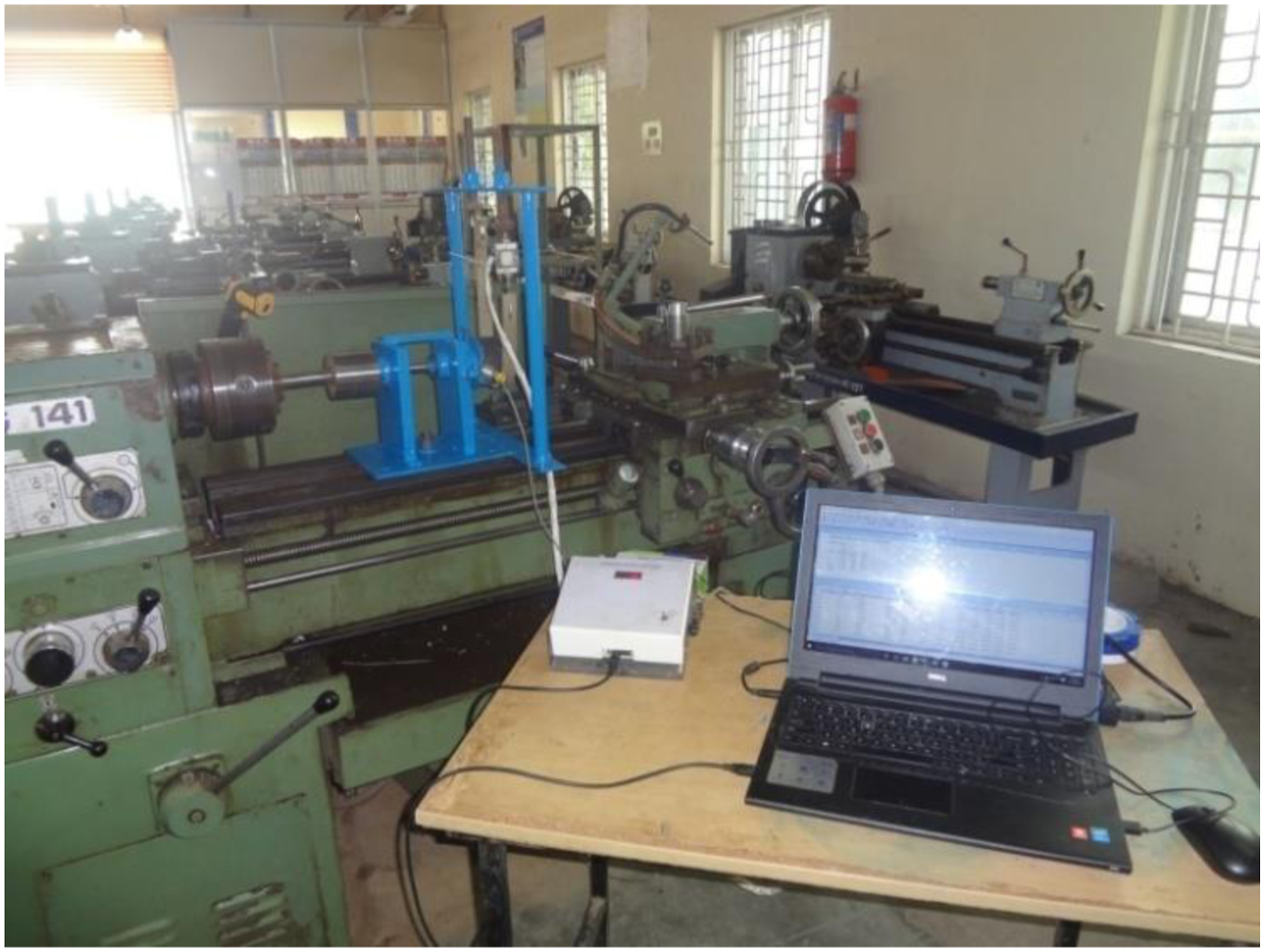
Evaluation criteria of compliant centrifugal clutches
Centrifugal clutches are transmitted torque utilizing frictional force (FF) developed between the clutch and clutch drum. Due to FF, the heat will be generated between the clutch and clutch drum, which should be dissipated. If more heat is produced at the contact interface, the polymers employed as clutch material may begin to soften and alter form. They are susceptible to temperature. Hence the speed of the clutch is limited to a maximum of 1000 rpm, and co-efficient friction (CoF) is assumed to be constant. Due to their low melting point, the polymer clutches cannot be used for heavy duty and automobile applications.
44
In this research work, the output responses torque (TQ), wear rate (WR), and contact temperature (CT) are measured and analyzed for maximum TQ and minimum WR and CT. The torque-carrying capacity of the compliant centrifugal clutch is measured through the following steps: 1. Start the computer-aided torque data logger. 2. Set the speed to 800 rpm in the lathe. 3. Check whether the input speed matches with output speeds. 4. Once the speeds are the same, gradually increase the load until the compliant centrifugal clutch slips (The point where the input and output speeds are different). 5. Final data are accurately captured in the computer. 6. The experiments are repeated for L27 orthogonal array, and the data are tabulated. 7. The torque is calculated using equation (2).


Temperature distribution on compliant centrifugal clutch
In this research work, the maximum contact temperature is measured at the outer surface of the compliant centrifugal clutch, and the temperature before the test is measured at the hub of the clutch (room temperature). From the measured temperatures, the temperature over some time is calculated by applying the following analytical equations 46 :
Fourier number is calculated by
Biot number is calculated by
The temperature (T
o
) at any time is calculated by
The temperature (T
r
) at any radius is calculated by
Results and discussion
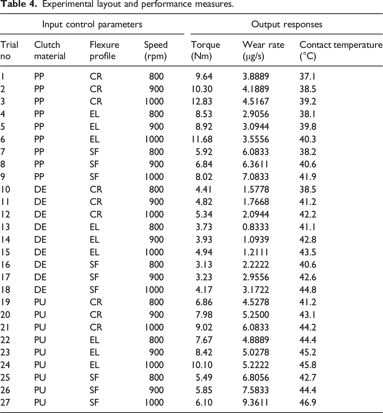
Figure 6 shows the 27 fabricated compliant centrifugal clutch assemblies made of different materials with different profiles for experimental analysis. Table 4 shows the measured responses obtained from different experimental runs. Fabricated compliant centrifugal clutch of (a) PP (b) DE and (c) PU with CR EL and SF profiles. Experimental layout and performance measures.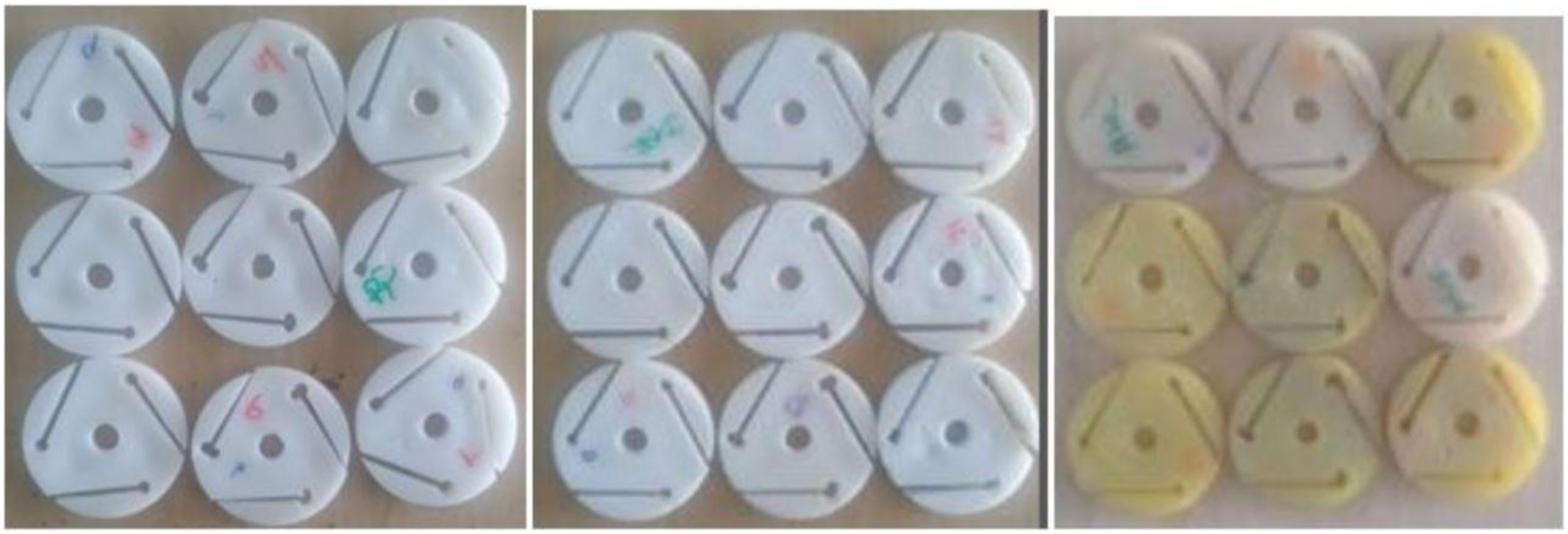
From the experimental runs, it is observed that when the material changes from DE to PP, the torque carrying capacity increases by 119.34%, the wear rate increases by 146.28% and the temperature slightly decreases by 6.25%. When the material changes from PU to PP, the increase in torque is 22.52%, wear rate and contact temperature decrease by 23.89% and 11.11%, respectively. The torque increases due to higher yield strength to young’s modulus ratio of PP.
47
When the flexure profiles changed from EL to CR, the torque and wear rate increased by 4.61% and 17.90%, respectively, and the contact temperature decreased by 3.79%. It is observed that a wear rate and temperature decrease by 52.31% and 4.57% respectively but the torque increases by 31.53% if the profile changes from SF to CR. If the speed increases, torque carrying capacity also increases.
48
When speed increases from 800 rpm to 900 rpm, torque increases by 8.86%, and 900 rpm–1000 rpm increases by 19.77%. The correlation between dependent and independent factors is presented as contours in Figure 7. Relationship between the inputs and outputs.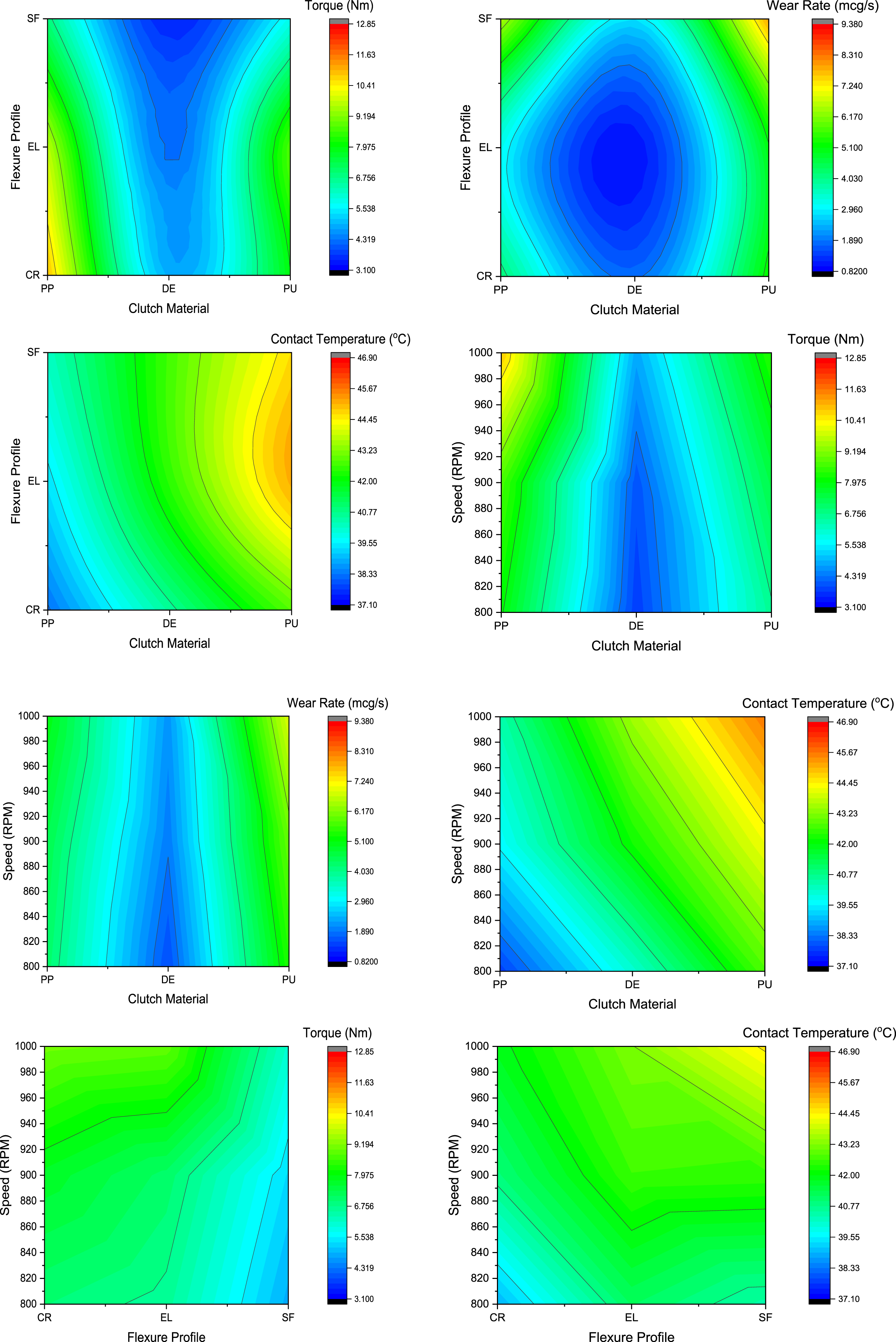
The torque carrying capacity is determined analytically for each clutch (27 trials) based on equation (5.2). Figure 8 shows the experimental and analytical torque data for all trials. It is visualized that the data obtained from experiments showed satisfactory agreement with those obtained from the analytical method. The centrifugal clutch’s TQ-carrying capacity increases with rotational speed. PP produces a higher torque-carrying capacity out of the three polymers due to the higher temperature-withstanding capability. The circular profile is the best of the three, producing higher torque-carrying capacity. Comparison of experimental and analytical torque for different materials, flexure profiles and speeds.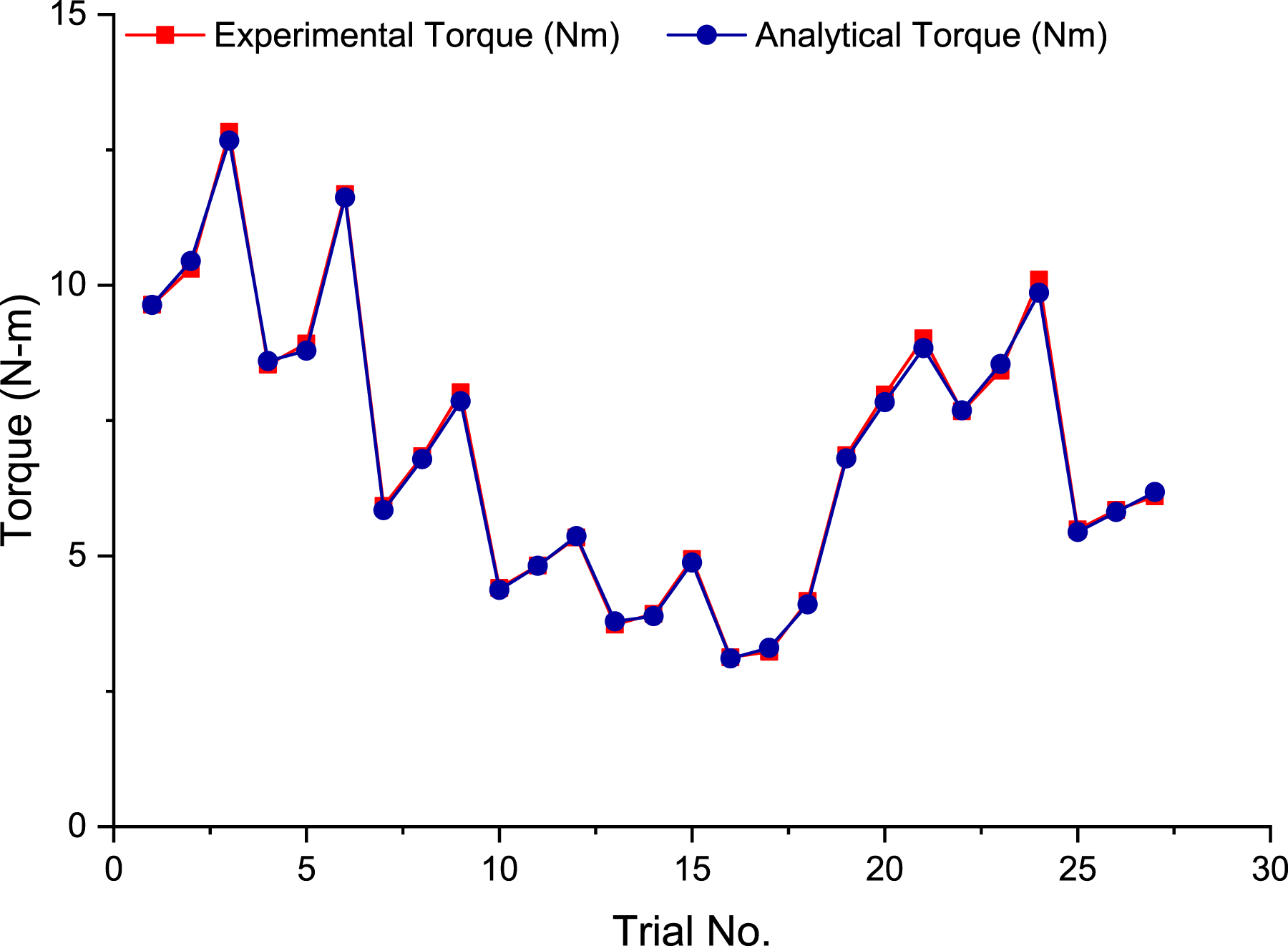
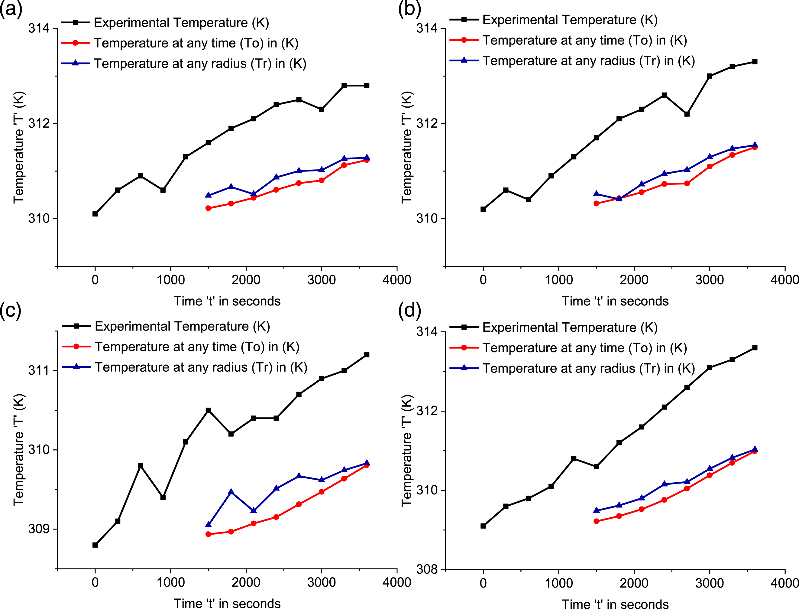
Similarly, the measured temperature data for an hour is compared with analytically calculated values based on equations (4)–(7). From Figures 9 and 10, it can be decided that the measured and calculated temperatures are in good agreement. It is observed that the % deviation in all the cases is minimum. It reveals that the performance of the clutch is worthy within the limit. In this work, 27 experimental trials were conducted for different materials, flexure profiles, and speeds. The simulated results of the entire set of experimental trials are examined. The outcomes of the experiment show that the contact temperature tends to increase with an increase in the operational time. Friction between the steel hub and polymer material is the reason for the increased interface temperature. But no drastic change or rise in interface temperature is sensed due to the lower coefficient of friction of polymer materials which produces less friction and thereby increases the performance of the centrifugal clutch.49,50 Comparison of experimental and analytical contact temperature (a) PP, CR and 800 rpm, (b) PP, CR and 900 rpm, (c) PP, CR and 1000 rpm, (d) PP, EL and 800 rpm. Comparison of experimental and analytical contact temperature (a) PP, EL and 900 rpm, (b) PP, EL and 1000 rpm, (c) PP, SF and 800 rpm, (h) PP, SF and 900 rpm.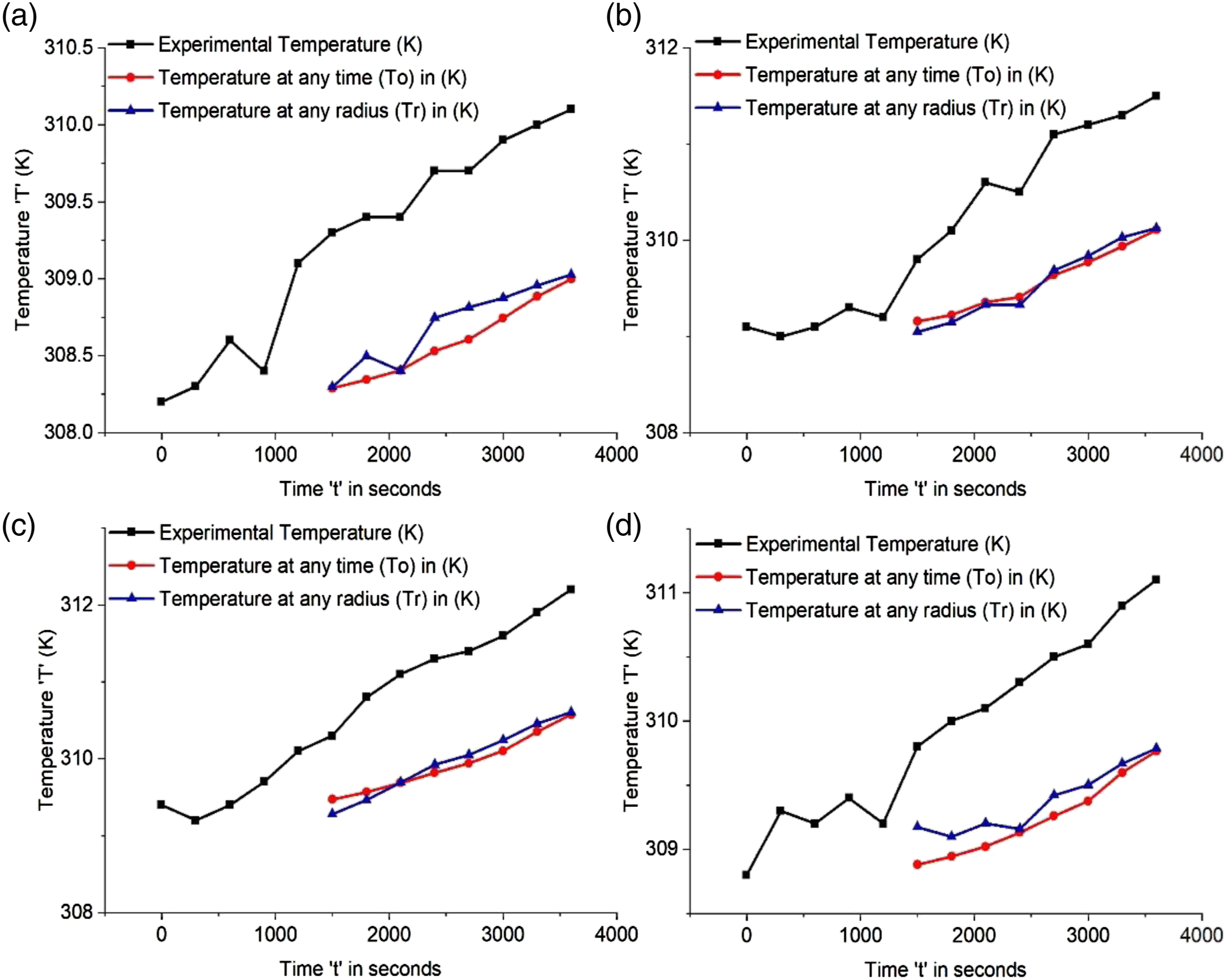
Normalized and weighted normalized matrix in TOPSIS for different clutch materials, flexure profiles, and speed.
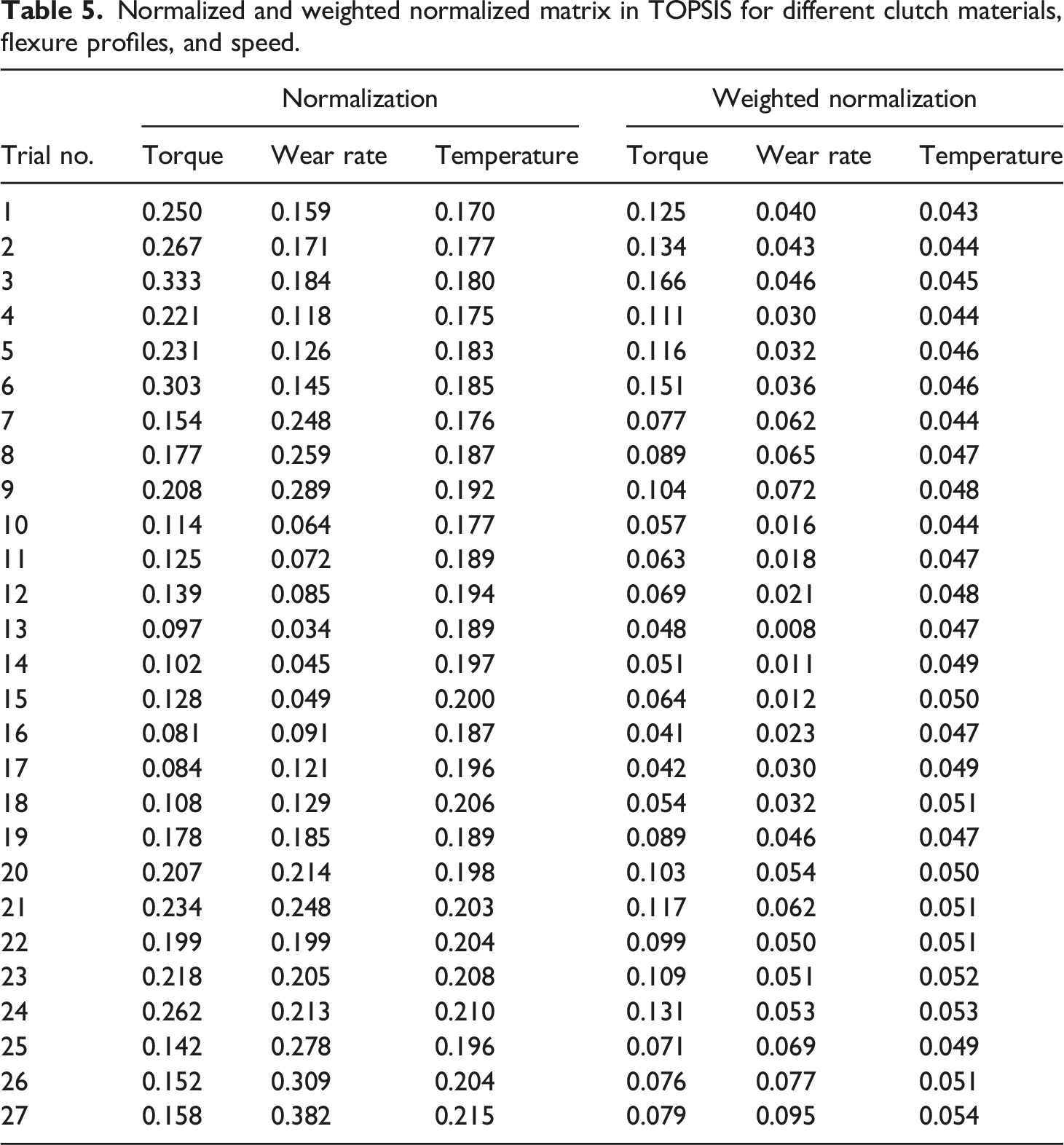
The most important function of the clutch is to transmit torque which is the intended usage of a clutch and the second important parameters are the contact temperature between the hub and clutch material and the wear rate of polymer centrifugal clutch material. Hence more weightage is given to torque (WTQ = 0.5), and equal weightage is given to contact temperature (WCT = 0.25) and wear rate (WWR = 0.25). The weighted normalised value W27 × 3 is calculated, which is also presented in Table 5.
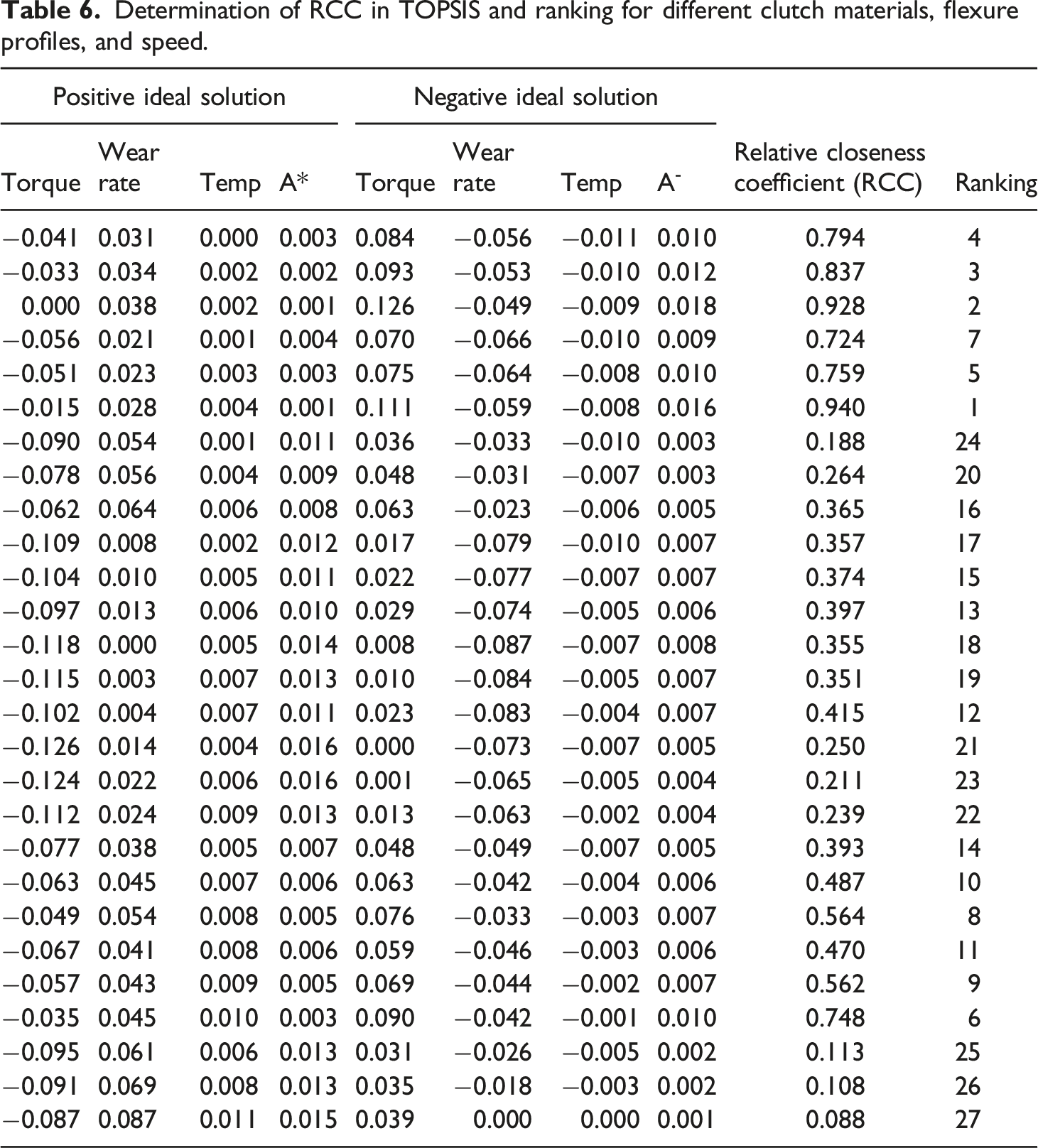
Determination of RCC in TOPSIS and ranking for different clutch materials, flexure profiles, and speed.
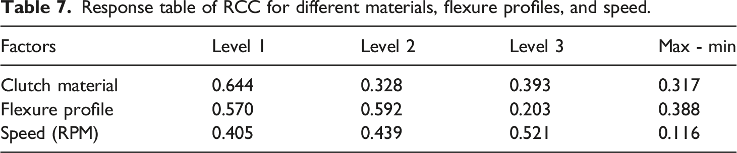
Response table of RCC for different materials, flexure profiles, and speed.
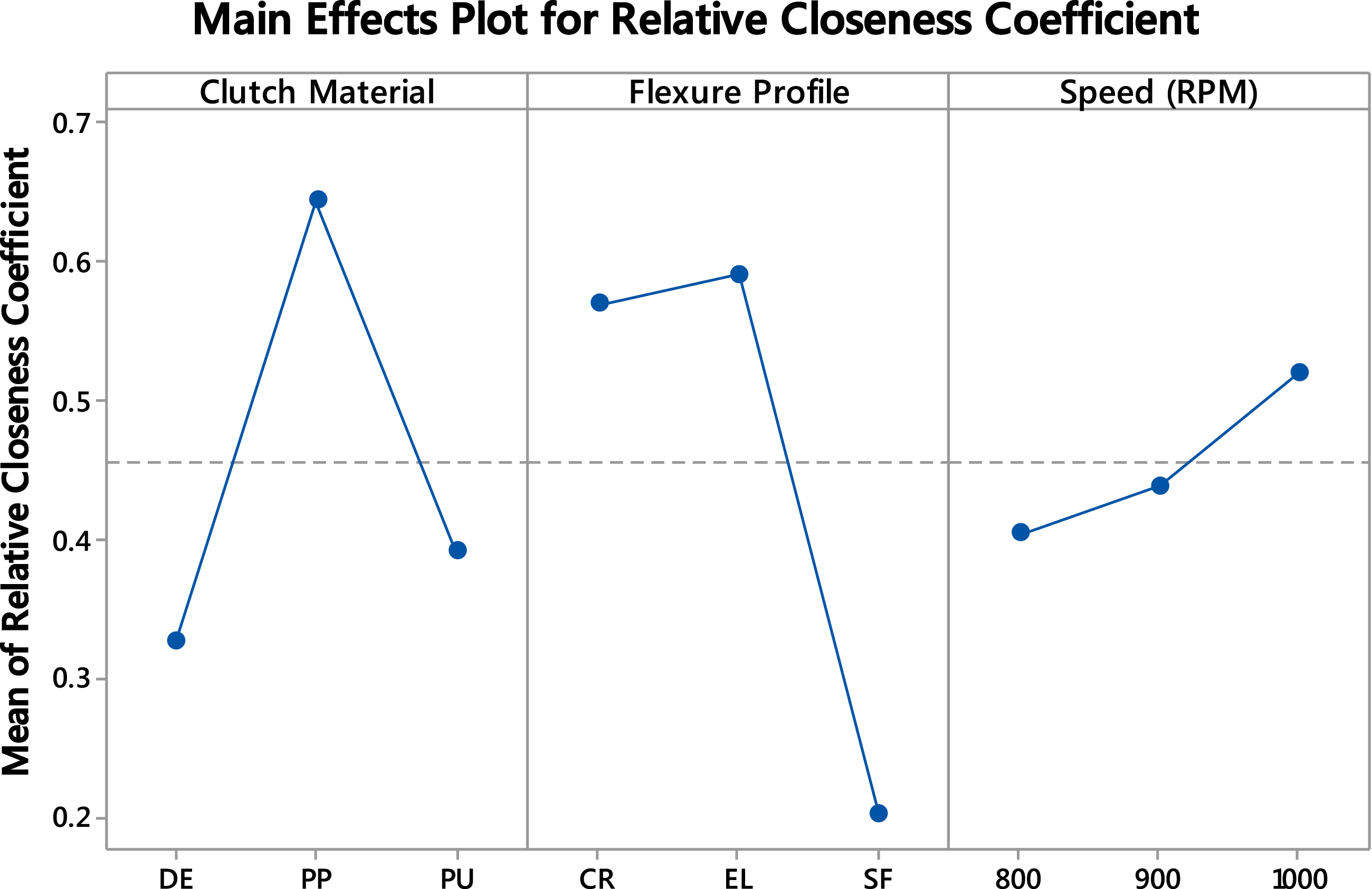
Main effects plot for RCC for different materials, flexure profiles, and speed.
An interaction plot analyzes the significant parameter effects over the output. The interaction plot of the influenced parameters on the RCC is shown in Figure 12. When the plots appear as parallel lines without any crossings, there is no interaction between the two inputs. When there are non-parallel lines, it specifies the unique relationship between the corresponding inputs. In this study, since parallel lines show their relationship, it is understandable that no appreciable interaction is seen among the inputs under consideration. Interaction plot of RCC for different materials, flexure profiles, and speed.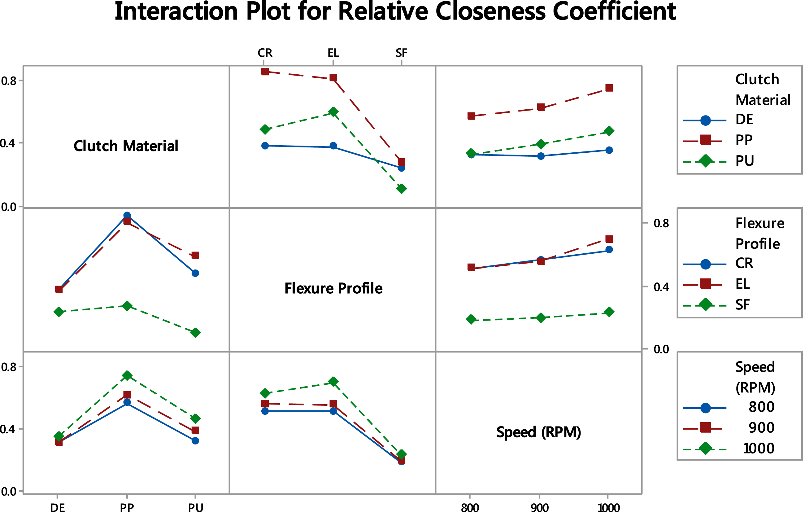
ANOVA table for RCC for different materials, flexure profiles, and speed.
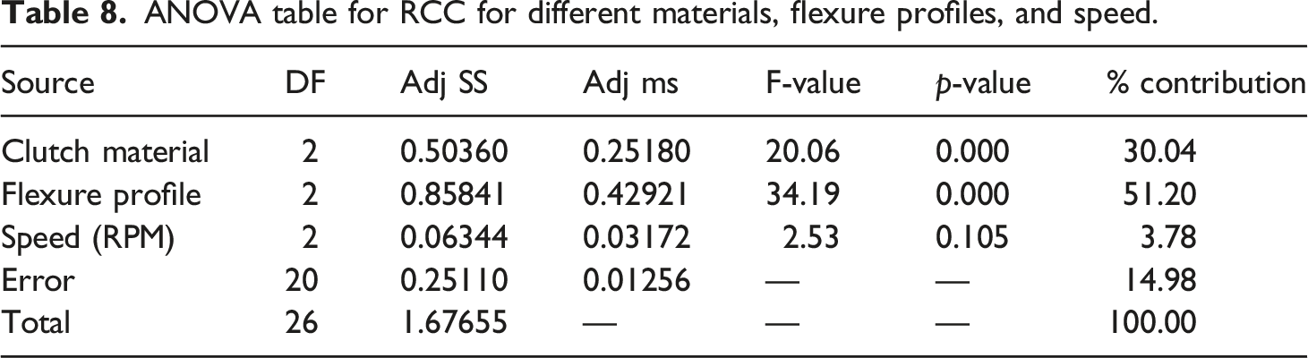
From ANOVA results of S = 0.11,198, R2 value = 85.04%, and R2 (Adj.) = 80.56%, it is evident that the model developed is good, and also R2 and R2 (Adj.) values are significantly closer to the ideal value of 100%. About 51.20% contribution by the flexural profile of compliant centrifugal clutch makes it the most influential parameter; the material considered for a clutch for about 30.04%, and the contribution of the rotating speed is 3.78% which is negligible, the occurred error is 14.98%. The graphical illustration is shown in Figure 13. ANOVA % contribution of input parameters.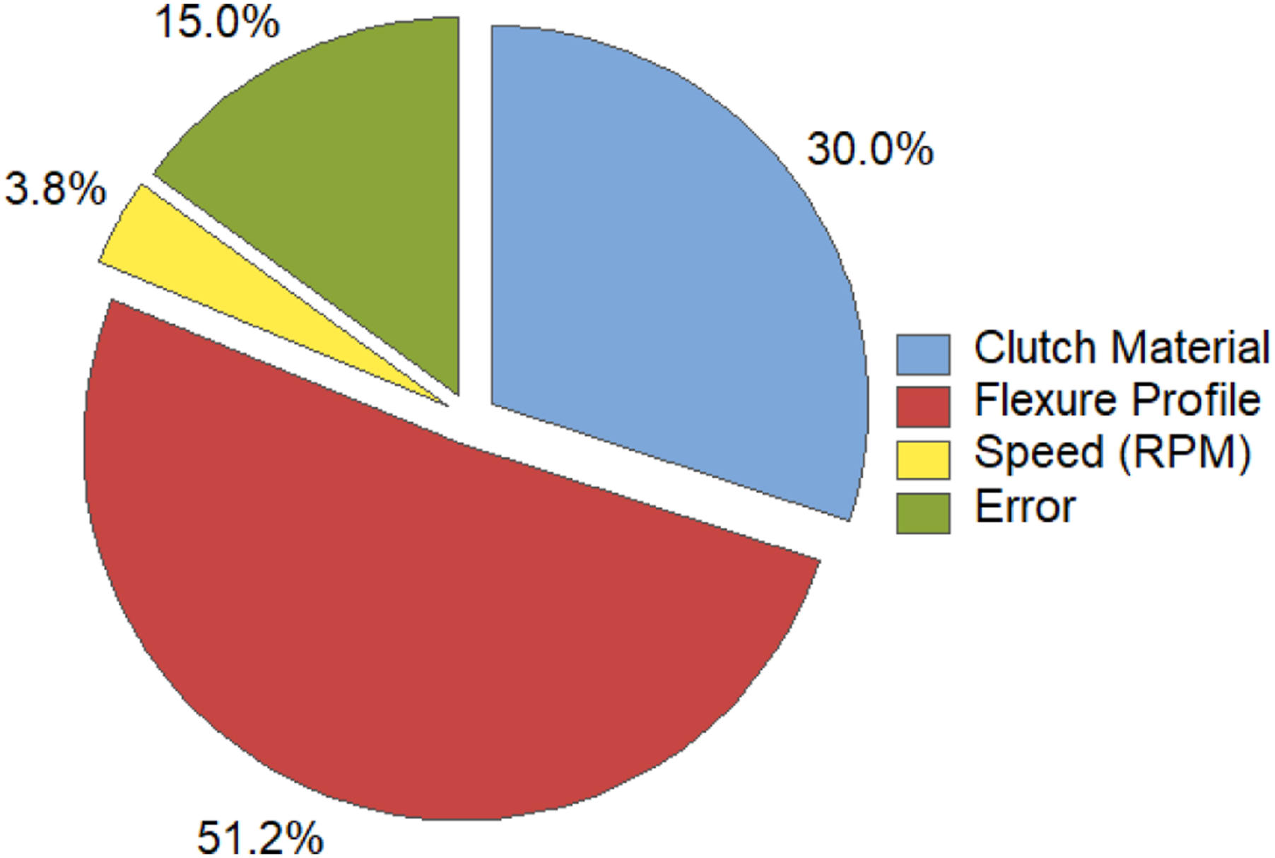
Uncertainty analysis
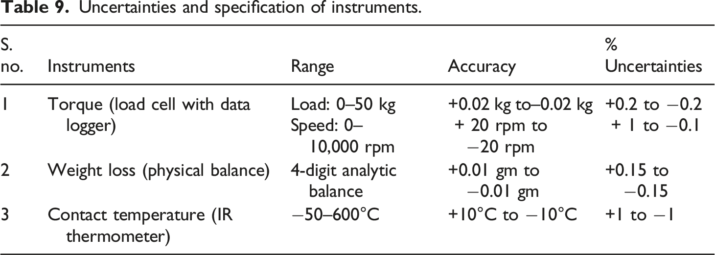
Uncertainties and specification of instruments.
Conclusion
The investigations on a compliant centrifugal clutch and a novel compliant double wishbone suspension system have been studied and presented. The experiments are conducted to find the suitable material, flexure profile, and geometrical parameters for the developed compliant centrifugal clutch. The conclusion arrived from the present work is presented in the following sections: • By changing the compliant centrifugal clutch material from DE to PP, the torque carrying capacity increases by 119.34%, the wear rate increases by 146.28%, and the temperature decreases by 6.25%. When the material changes from PU to PP, the increase in torque is 22.52%, and wear rate and contact temperature decrease by 23.89% and 11.11%, respectively. • When the flexure profiles changed from EL to CR, the torque and wear rate increased by 4.61% and 17.90%, respectively, and contact temperature decreased by 3.79%. It is observed that a decrease in wear rate and temperature by 52.31% and 4.57%, respectively, but the torque increases by 31.53% if the profile changes from SF to CR. • As rotational speed increases, torque carrying capacity also increases. For example, from 800 to 900 rpm, torque increases by 8.86%, and from 900 to 1000 rpm, it increases by 19.77%. • In the TOPSIS method, the optimal condition achieved is polypropylene as compliant centrifugal clutch material having an elliptical flexure profile running at 1000 rpm. The interaction plot does not show any inter-relationship among the considered parameters in both TOPSIS and DEAR method.
The future scope of work involves fatigue testing, material selection, and metal inserts with polymers to avoid stress relaxation. Generally compliant centrifugal clutch involves more considerable deflections. The highly nonlinear deflections complicate the analysis and design approaches. Also, the components manufactured from polymers often reveal lower creep life and fatigue life, which are all the limitations of this study.
Footnotes
Declaration of conflicting interests
The author(s) declared no potential conflicts of interest with respect to the research, authorship, and/or publication of this article.
Funding
The author(s) received no financial support for the research, authorship, and/or publication of this article.