
Abstract
Drilling polyetherimide composite is difficult due to the anisotropic and inhomogeneous structure of fiber and matrix. Drilling of fiber-reinforced composites is a thermo-mechanical friction procedure required in various aerospace and automotive applications. The major reason for component rejection during manufacturing processes is due to thermal damage and temperature elevation defects such as delamination and fiber pullout caused during drilling. This work aims to propose a rotary ultrasonic-assisted drilling technique for composite materials to reduce thermal damage using diamond-impregnated tools. The influence of drilling parameters such as rotational speed, feed rate, abrasive grit size, and ultrasonic power was monitored on temperature elevations. The temperature was monitored using thermocouples located at different distances of 1.0, 2.0, and 3.0 mm from the main drilled hole. The response surface methodology was used for the design of experiments during the drilling of composite material and optimization of process parameters was carried out using analysis of variance. Rotational speed and abrasive grit size were observed to have the highest contribution of 42% and 37% for temperature elevations respectively. It was witnessed that temperature increases with an increase in rotational speed, feedrate, and abrasive grit size. Increasing the ultrasonic power during drilling temperature can be minimized. The temperature elevations at the tool-composite interface can be reduced by leveraging the application of rotary ultrasonic-assisted drilling.
Keywords
Introduction
The composite materials are broadly used in various industries such as automobiles, aviation, aerospace, architecture, sports equipment, marine, turbomachinery, and electronic shielding.1–4 Polyetherimide composite has been widely utilized due to their cost-effectiveness and unique properties.5–7 The excellent mechanical properties of polyetherimide composites ensure easy machining, high dimensional rigidity, and high strength.8–10 High temperatures during composite drilling influence micro and macro geometrical damages such as delamination, hole quality, microcracks, fiber pullout, and surface morphology damage.11–13 Various methods were used in the literature to monitor temperature change during drilling processes such as thermocouples, photographic images, infrared pyrometers, and thermal cameras.14–16 During drilling, thermocouples are mostly used for adequate measurement of temperature elevations. Composite drilling involves converting mechanical energy into thermal energy, causing a temperature rise of the composite and drill tool continuously. During the composite drilling, direct contact at the tool-composite interface results in significant amounts of friction, temperature generation and heat accumulation due to the removal of material. Temperature increases near the drilling site can result in thermal degradation, delamination, fiber pullout, microcracks and surface topology defects resulting to weakens the strength and rejection of composite material.
There are various methods of drilling in the literature to reduce the thermal damage at the drill site of composite material.17–24 One of the most used machining methods for composites drilling is ultrasonic drilling (UD). Ultrasonic drilling has proved its effectiveness in drilling brittle materials that are also hard independent of their electrical properties. The material removal mechanism is through abrasion by slurry suspended with abrasive particles, which is introduced at the rotary tool and workpiece interface. 25 Rotary ultrasonic drilling (RUD) is an advanced hybrid non-traditional machining process that utilizes the synergetic effect of conventional machining and diamond grinding by employing a tool impregnated with diamond abrasives.26–29 Cong et al. 30 studied the influence of temperature during RUD of carbon fiber-reinforced polyetherimide (CFRP) using two different temperature measurement techniques, fiber optic sensors and thermocouples. The dynamic relationship between the process parameters and temperature has also been determined. It was observed that temperature increases with increasing the spindle speed of tool. Wang et al. 31 studied the effect of temperature on the quality and properties of machined CFRP composite.
Zou et al. 32 observed the temperature rise during RUD of composite material. It was observed that ultrasonic power has an important impact on cutting temperature. The authors ascertained cutting temperatures at four different ultrasonic powers (0, 20, 40 and 60%). Lotfi et al. 33 used rotary ultrasonic-assisted milling of CFRP and titanium to improve the surface morphology at drill site. Kumaran et al. 34 attempted RUD of CFRP composite. It was observed that RUD in a cryogenic domain delivered a reduced burr region and surface roughness. Chen et al 35 studied the influence of drilling parameters on temperature elevations and delamination. It was observed that the cutting temperature decreases with decreasing feedrate during drilling. Gupta et al. 36 employed RUD of porcine bones to monitor temperature elevations. The influence of drilling parameters such as spindle speed, feedrate, drill diameter and amplitude on temperature rise during RUD was studied. It was concluded that temperature increases with an increase in tool speed, drill diameter and feedrate. Agarwal et al. 37 observed a decreasing trend of temperature rise with an increase in vibrational amplitude during RUD. Gupta et al. 38 compared the drilling of bones with conventional and ultrasonic drilling using hollow drill tools. It was observed that drilling with ultrasonic-assisted drilling using a hollow tool resulting lower temperature rise.
Polyetherimide composites have various attractive properties in automotive and aerospace applications. But the temperature elevations and thermal damage during the conventional drilling of composite influence the surface morphology, defects, damage, and mechanical properties of the polyetherimide composites. Hence, there is a need for an efficient drilling process to minimize temperature rise during drilling to avoid thermal damage and drill-induced defects. The key focus of this study is to minimize heat generation during the drilling of composite material leveraging rotary ultrasonic-assisted drilling using a diamond-impregnated hollow drill tool. The influence of various drilling parameters such as rotational speed, feed rate, abrasive grit size, and ultrasonic power was observed on temperature rise. The temperature was monitored using thermocouples. Response surface methodology was used for the design of experiment for drilling. The in-situ monitoring of temperature elevations and optimization of drilling parameters during rotary ultrasonic drilling of composite material is the key contribution of the present work.
Material and methodology
Workpiece details
The workpiece used for the present study is polyetherimide composites (PEC) which were fabricated using carbon fibers of polyetherimide and a solution of dichloromethane. During the fabrication of the composite, the solution was prepared and cutting of carbon fabric was done. The direction of cutting of fabrics strongly impacted the wear function of the workpiece. After cutting the fibers, the solution was poured over the carbon fiber to dip uniformly. Fabrics were taken out of the solution and dried under pressure. During the last step, the compression of fabric was achieved by using a moulding machine. The detailed steps of fabrication were discussed in our previously published article. 39 The density of composite was 1.28 g/cm3, a glass transition temperature of 217°C, 40 a process temperature ranging from 330°C to 390°C, 41 and a degradation temperature of 400°C. 42
Experimental setup
For the drilling investigation of composite material, a hollow drill tool was designed and manufactured. For the drill tool, the shank diameter was fixed at 6.5 mm. The hollow tools had an inner diameter of 2.8 mm and an outer diameter of 4.5 mm. Experiments were conducted with a diamond-impregnated tool with varying the grit size of abrasives. Diamond abrasive particles were electroplated on an EN-31 steel hollow shank. The diamond-impregnated tool was fixed in the ultrasonic transducer to act as an ultrasonic horn during drilling as illustrated in Figure 1(a). The experimental study was carried out on a CNC milling machine with the attached assembly of the ultrasonic horn as shown in Figure 1(b). The mild steel vertical angle rod was connected to the spindle head. Carbon brushes along with tool holders were installed on these steel rods. The carbon brushes were connected to the slip rings that provide voltage signals to the ultrasonic horn to perform rotary ultrasonic-assisted drilling of the composite. (a) Schematic of ultrasonic tool assembly, (b) experimental RUD setup.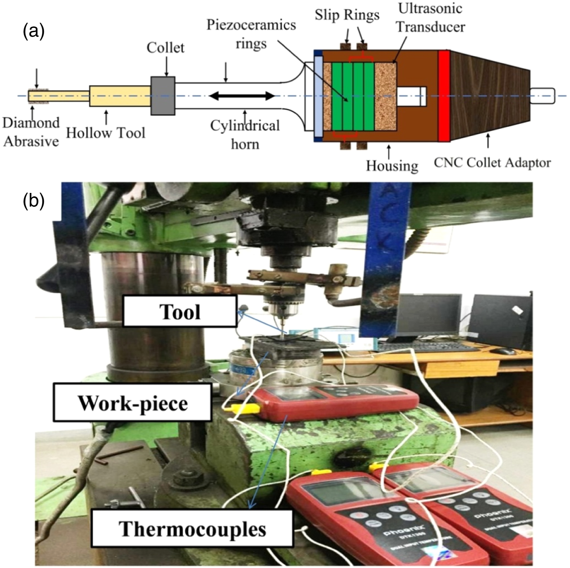
All experiments were conducted on the same drilling setup and the corresponding temperature was monitored using k-type thermocouples. Three different k-type digital thermocouples were placed in the predrilled craters in the polyetherimide composites at three different positions (1.0, 2.0 and 3.0 mm). The schematic diagram for thermocouples position from the main drilled hole is presented in Figure 2 k-type thermocouples with an accuracy of ±0.3%°C were used to record temperature elevations. Before recording the value of temperature, all digital thermocouples were calibrated carefully. The initial value (T
in
) and final value (T
fin
) of temperatures were noted with each digital thermocouple, and changes in the temperature (ΔT) were ascertained to obtain a set of optimal parameters for the generation of minimum temperature. The experiments were conducted at room temperature. (a) Location of thermocouples from the drilled crater, (b) Phoenix thermocouple (K type) with Al–Cu probe.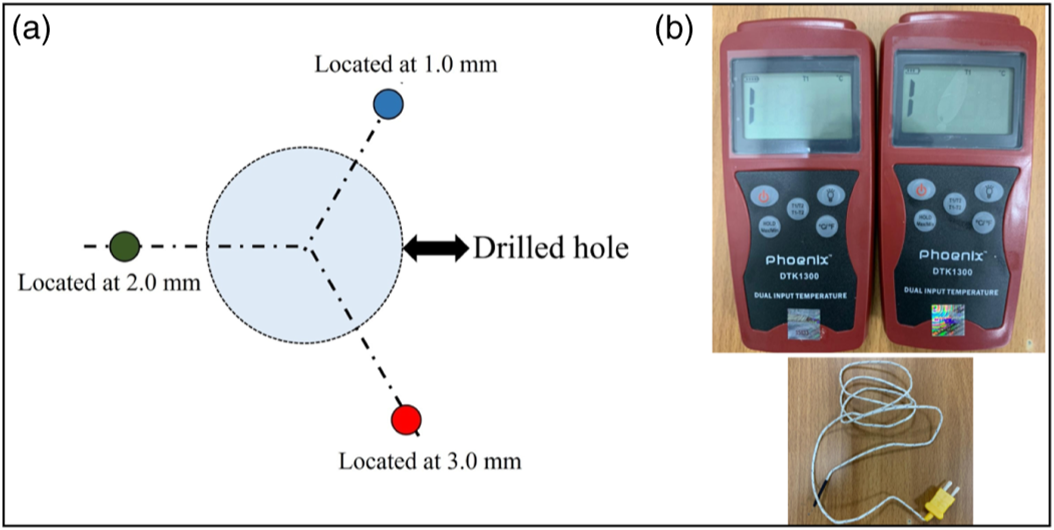
Process parameters and design of experiments
Input process parameters and their different levels.
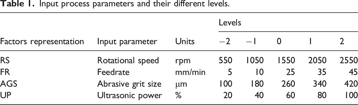
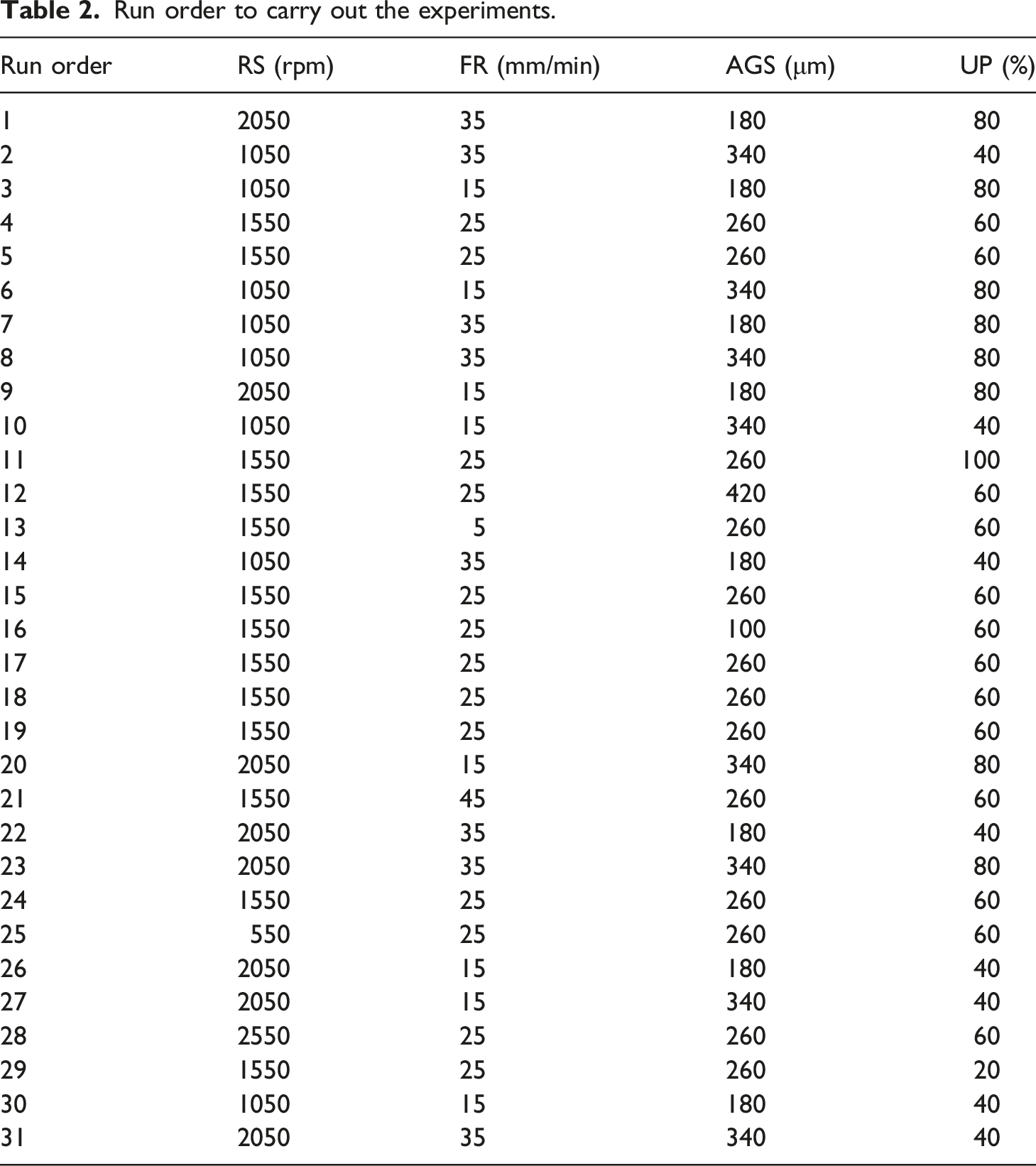
Based on the physical foundation of the developed RUM setup, the range of ultrasonic power was determined. This drilling setup was designed to support ultrasonic power at 100%. Hence, the ultrasonic power range was set from 20 to 100%. Using the central composite design, the drilling experimentation was conducted after selecting the range of input process parameters.
Experimentation in the current investigation was planned to ascertain the influence of control factors of RUD on temperature elevations. Design of experiments (DOE) is one of the essential steps in an exploratory study involving statistical analysis. Different design methodologies such as Taguchi methodology, orthogonal arrays, response surface methodology (RSM) etc. Are widely used in experimental research for the minimization of experiments and to draw valid conclusions from experimentation.
Run order to carry out the experiments.
Summarized data of temperature at different locations of thermocouples.
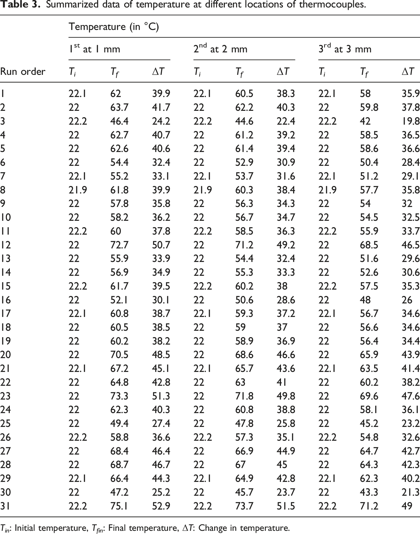
T in : Initial temperature, T fin : Final temperature, ΔT: Change in temperature.
Results and discussion
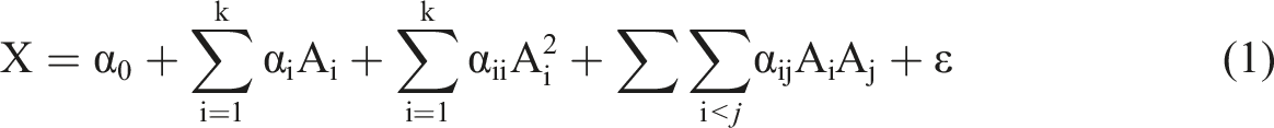
The data described in Table 3 were analysed using the standard procedure given by response surface techniques. Analysis of variance was performed to observe the influence of parameters on the temperature. The mathematical modelling and data examination have been discussed below.
Mathematical modelling of temperature
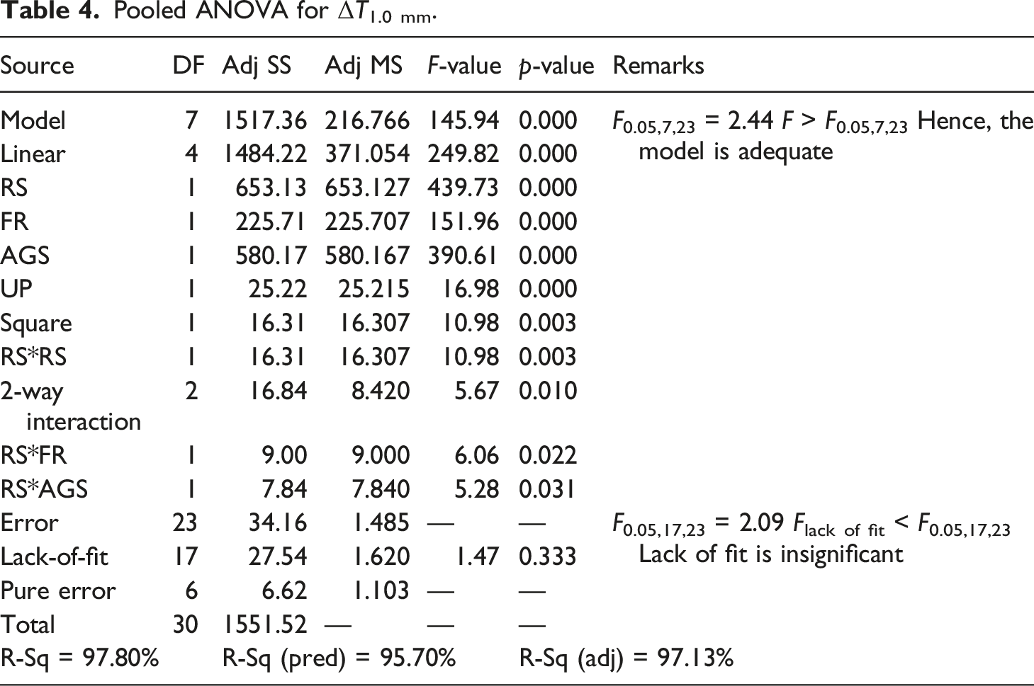
Pooled ANOVA for ΔT1.0 mm.
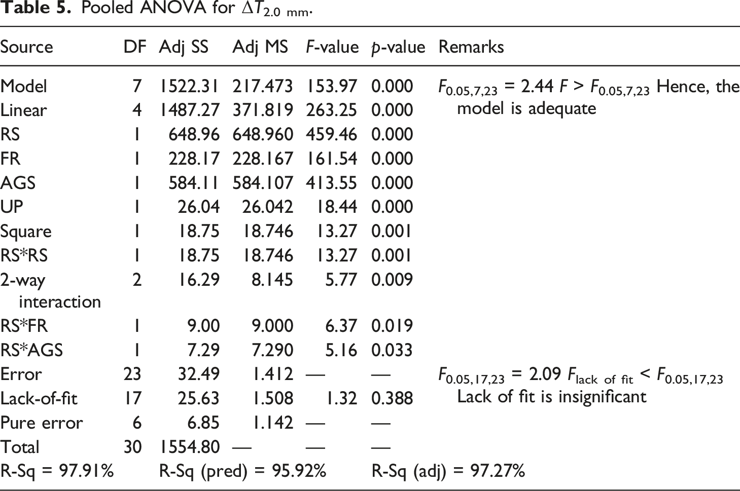
Pooled ANOVA for ΔT2.0 mm.
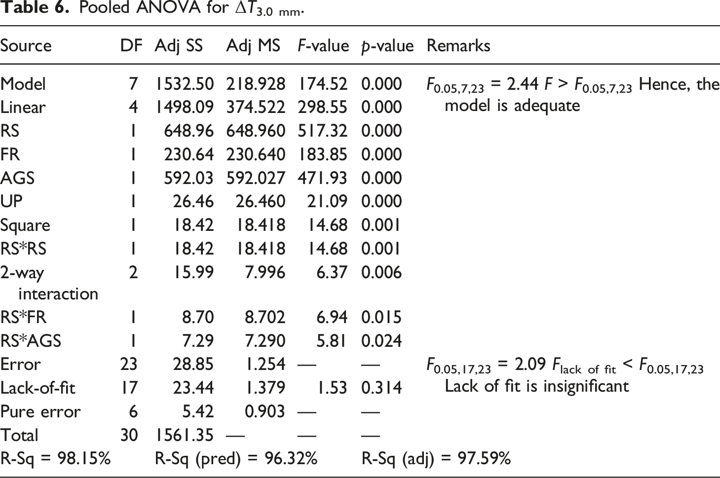
Pooled ANOVA for ΔT3.0 mm.
Adequacy of the developed temperature models
The adequacy and lack of fit of the proposed statistical models were checked and verified using the F-values from the ANOVA. F-values corresponding to the models are 145.94, 153.97 and 174.52, respectively, for cutting temperature at locations 1.0 mm, 2.0 mm and 3.0 mm from the centre of the crater. These measured F-values are greater than tabulated F- values given in the ANOVA Table corresponding to F0.05, 7, 23 = 2.44, which shows that models are adequate. Similarly, F- values for lack of fit of the proposed models are 1.47, 1.32 and 1.53 for cutting temperatures. The measured F-values are less than the tabulated F- values given in the ANOVA Table 4 corresponding to F0.05, 17, 23 = 2.09, which also shows that the lack of fit of proposed models is insignificant. Corresponding R2 values are also given in Table 5 for cutting temperature. Table 6 reveal that adjusted (R2) are reasonable and in agreement with (R2) predicted for all three cases. This authenticates the adequacy and reliability of the proposed regression models to predict temperatures. Thus, the proposed statistical equations can be used to predict the cutting temperature within the limit of parameter ranges as listed in Table 1.
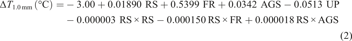
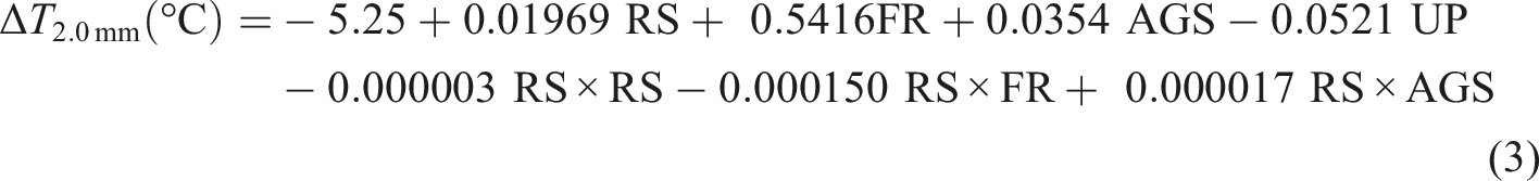
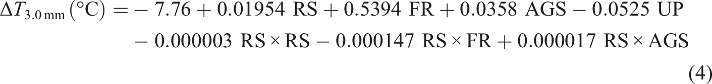
Precision of statistical models of temperature
A significant small irregular error is generated during experimental work and regression analysis. Therefore, it is necessary to check and validate the accuracy of the proposed models as represented by equations (2) to (4). The accuracy of these models is determined by equation (5).
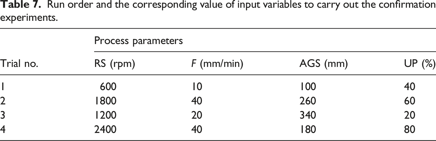
Run order and the corresponding value of input variables to carry out the confirmation experiments.
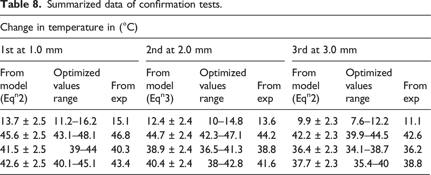
Summarized data of confirmation tests.
Influence of
RUD
control factors on temperature
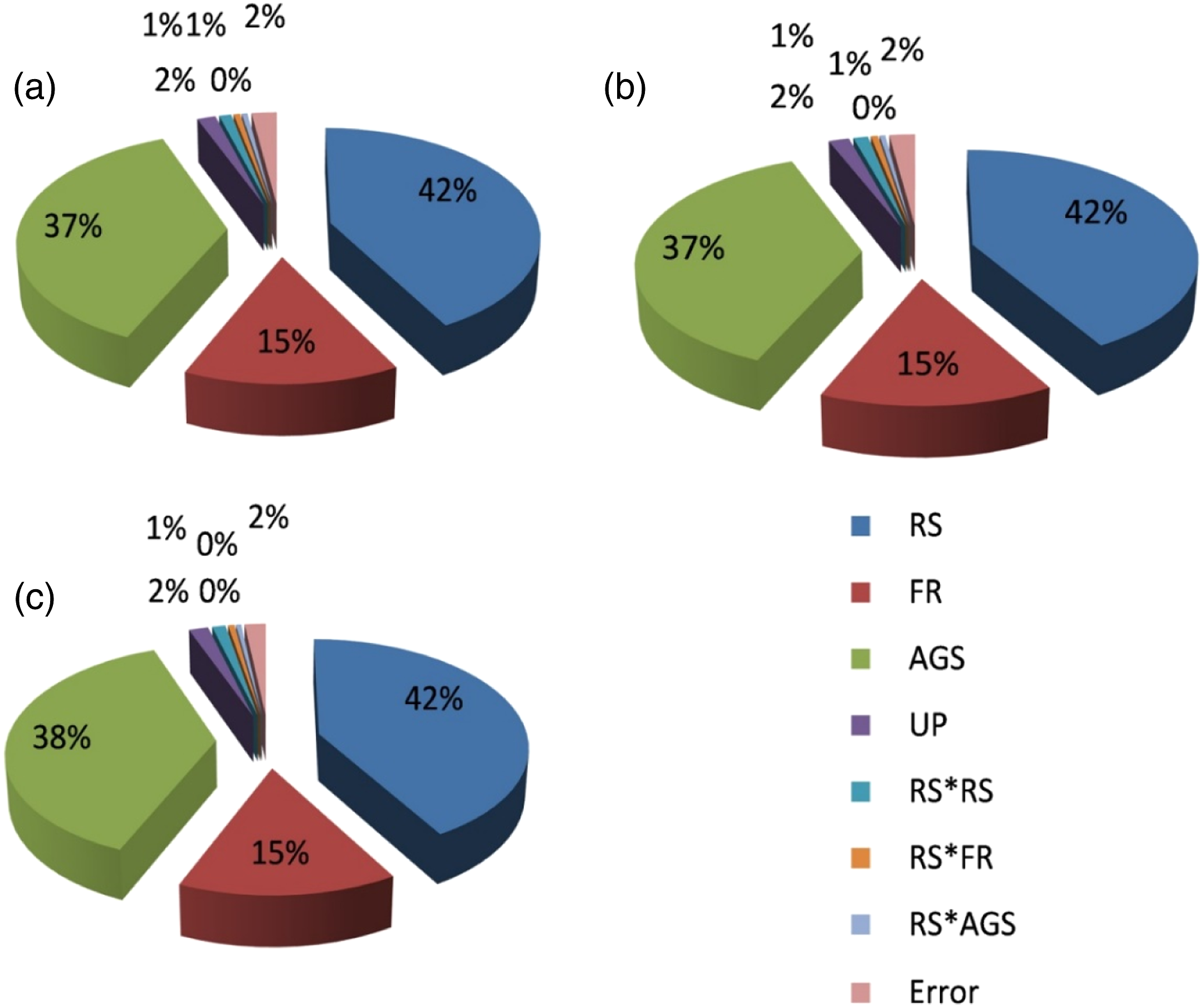
The effect of machining control factors on the temperature change of the workpiece is discussed in this section. Figure 3 demonstrates the main effect plots of the effects of drilling control factors on change in temperature at a fixed position of thermocouples: (a) at 1.0 mm, (b) at 2.0 mm, and (c) at 3.0 mm from the centre of the drilled crater. A similar trend of variation was seen for change in temperature of thermocouples located at three different places (Figures 3(a)–(c)) corresponding to various control factors. The percentage contribution of control factors on the cutting temperature regarding thermocouples located at different places has been demonstrated in Figure 4. Influence of drilling control factors on cutting temperature at a distance of (a) 1.0 mm, (b) 2.0 mm and (c) 3.0 mm. Percentage contribution of control factors on cutting temperature at a distance of (a) 1.0 mm, (b) 2.0 mm, and (c) 3.0 mm from the centre of the drilled hole.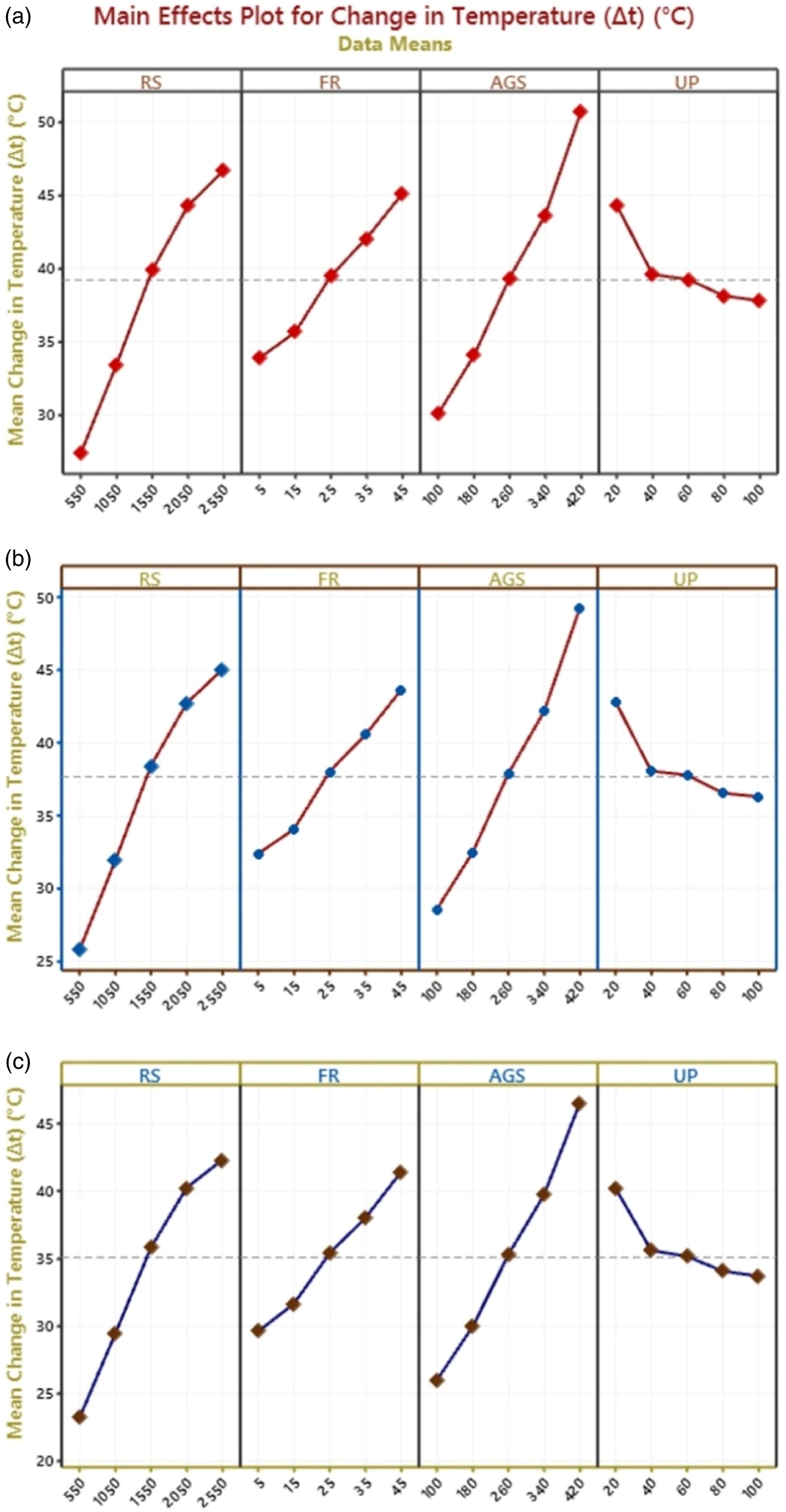
Rotational speed vs change in temperature
Figure 5 reveals that cutting temperature increased with the change in rotational speed from 550 r/min to 2550 r/min when other control factors are held constant. Because of friction and shear forces between the tool and the workpiece, cutting temperatures increase as spindle speed increases.
51
The analysis determined that the cutting temperature at a 1.0 mm distance from the thermocouple was 26.9°C at 550 r/min and 47.1°C at 2550 r/min. Figure 5 also demonstrated that temperature change attained near the boundary between the workpiece and tool, i.e. thermocouple, which was located at 1.0 mm, 2.0 mm, and 3.0 mm distance from the drilling crater surface. Gradually, the cutting temperature decreased as the distance between the thermocouple and the drilling crater surface increased. These effects match the results reported by previous studies of the RUD
30
and RUBD.36,38 Influence of rotational speed on change in temperature of thermocouples placed at three different positions from the drill hole. [FR = 25 mm/min, AGS = 260 μm and UP = 60%].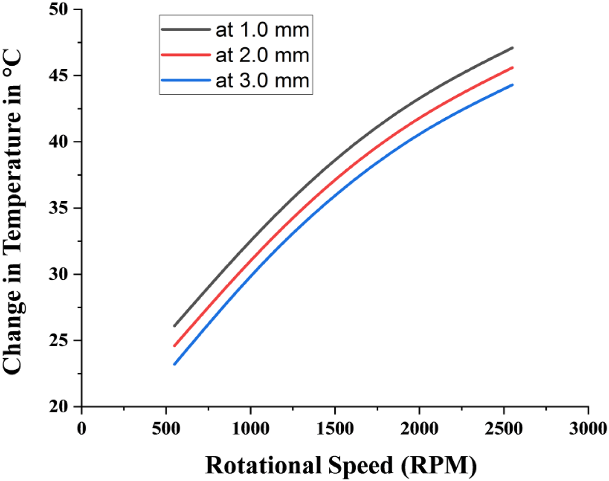
Feed rate vs change in temperature
Figure 6 reveals that cutting temperature is strongly affected by feed rate. Cutting temperature is increased linearly with an increase in feed rate from 5 mm/min–to 45 mm/min. An increase in feed rate presents worse material to the cutting tool per unit of time. More frictional forces exerted on the tool lead to more heat transfer to the workpiece, leading to higher temperatures on the drilled hole.
52
These effects match the outcomes presented in their investigational study on standard drilling and ultrasonic drilling.
53
Influence of feed rate on change in temperature of thermocouples placed at three different positions from the drill centre. [RS = 1550 r/min, AGS = 260 μm and UP = 60%].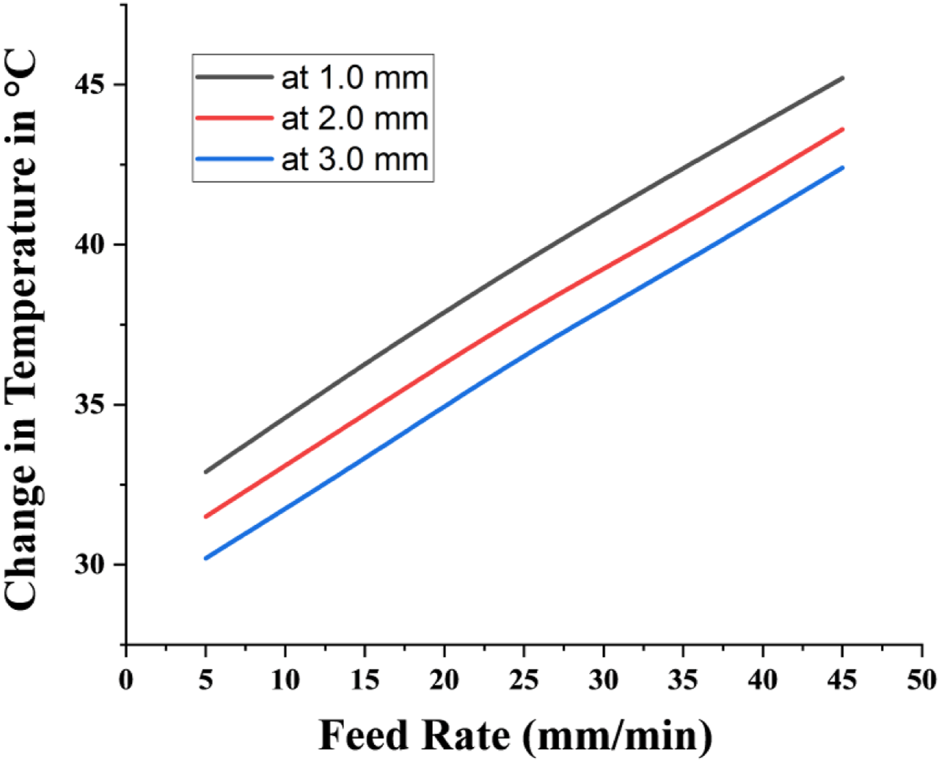
Abrasive grit size vs change in temperature
The influence of the grit size on cutting temperature is also examined for RUD. Figure 7 illustrates that the cutting temperature increased with the abrasive average grit size from 100 μm to 420 μm. This is attributed to an increase in the contact surface between the tool and workpiece by the rise in abrasive grit size. More frictional heat is generated, thereby increasing the temperature at the workpiece. Influence of abrasive average grit size on change in temperature of thermocouples placed at three different positions from the drill centre. [RS = 1550 r/min, FR = 25 mm/min and UP = 60%].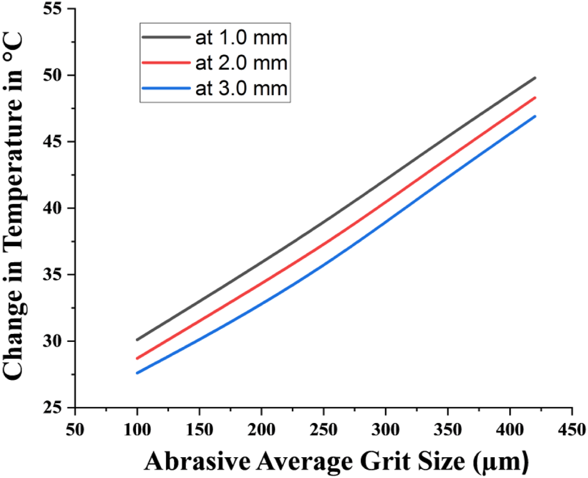
Ultrasonic power versus change in temperature
Figure 8 reveals that cutting temperature significantly decreases with an increase in ultrasonic power from 20% to 80%. This is because, in RUD, there is an irregular contact between the workpiece and the drill tool. The tool-workpiece contact ratio is reduced with an increase in ultrasonic vibrational power.
36
This effectively reduces the interaction of the drill with the workpiece per unit of time. So, less material is removed per unit of time from the workpiece, which lowers the heat. Influence of ultrasonic power on change in temperature of thermocouples placed at three different locations from the centre of dill. [RS = 1550 r/min, FR = 25 mm/min and AGS = 260 mm].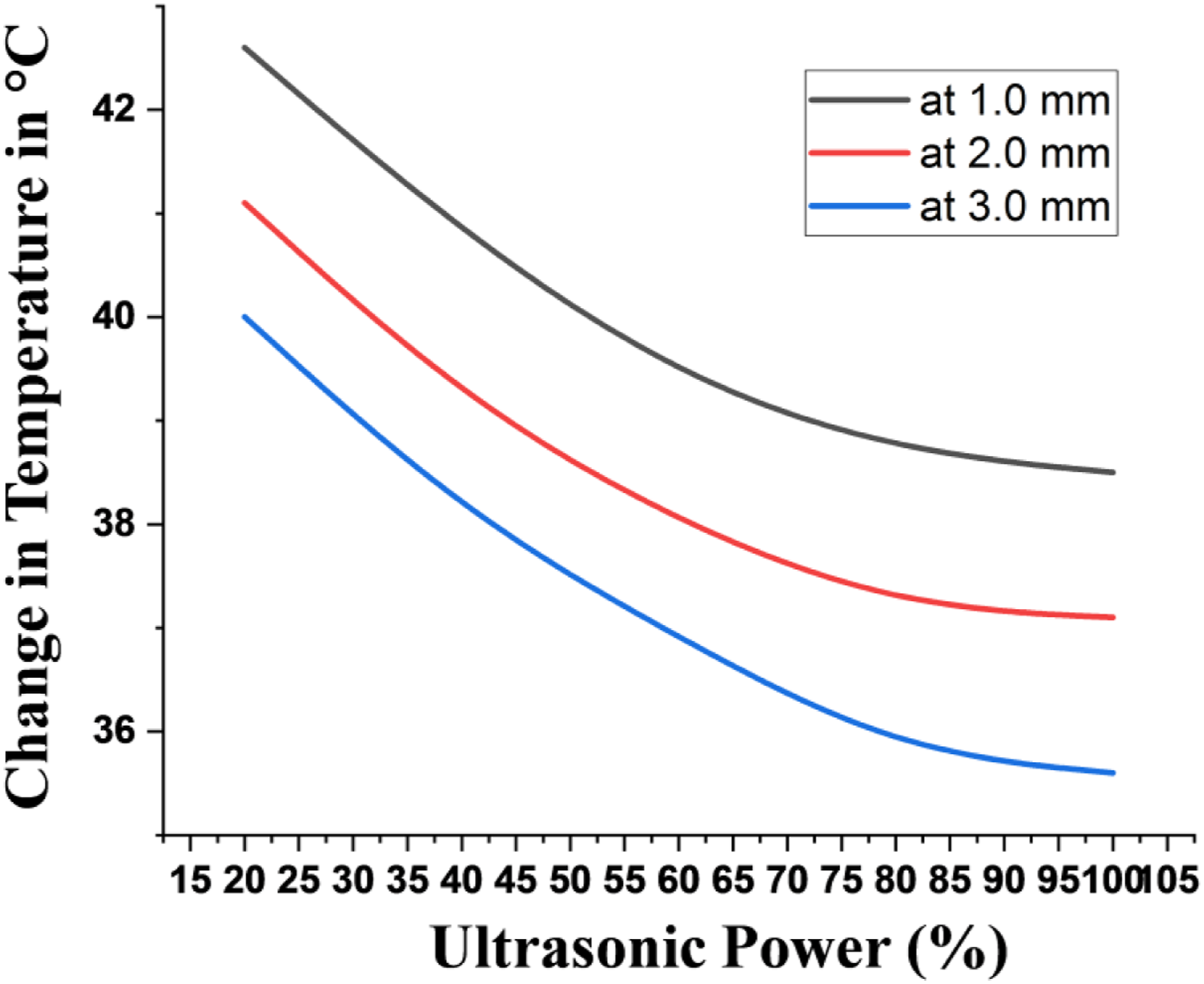
Interaction effects contributing to change in temperature
It was observed from equations (2) to (4) that significant interaction effects play an essential role in their impact on change in temperature. These interaction effects involve the interaction effect of RS and FR on temperature and the interaction effect of AGS and RS on temperature. These significant interactions of input factors on the cutting temperature of the thermocouple placed at a 1.0 mm distance have been plotted by using equation (2) and shown in Figures 9 and Figure 10. In line with the main effect plots, the trend of interaction plots of temperature readings at 2.0 mm and 3.0 mm from the centre of drilled hole exhibit the same trend as illustrated in Figures 9 and Figure 10. Interaction effect plot of RS and FR vs temperature (a) 3-D response surface plot (b) 2-D plot. [AGS = 260 μm and UP = 60%]. Interaction effect plot of RS and AGS vs temperature (a) 3-D response surface plot (b) 2-D plot. [FR = 25 mm/min and UP = 60%].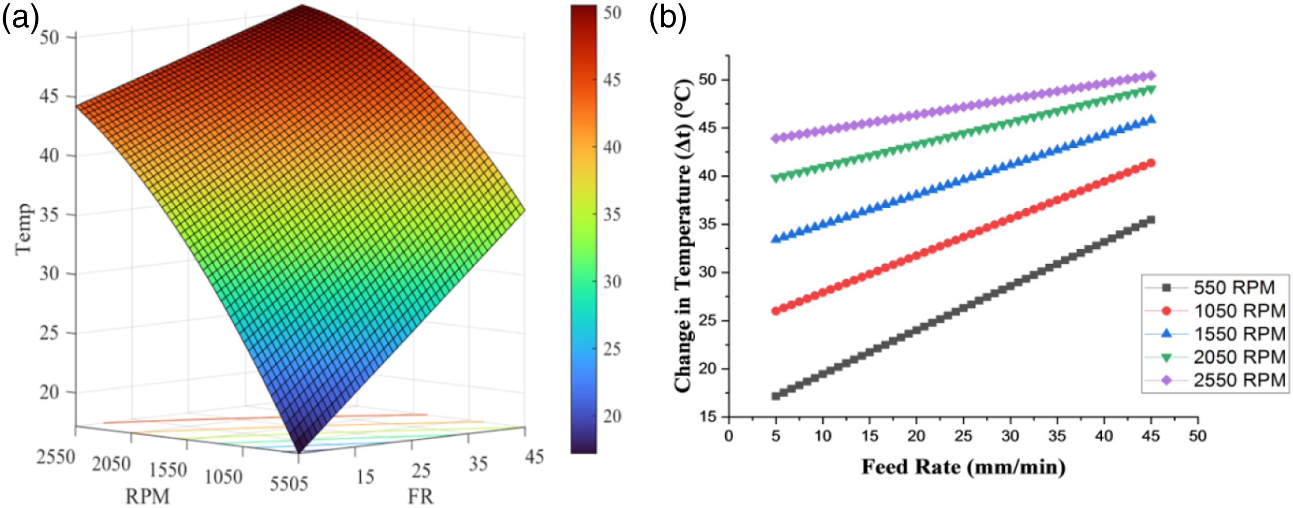
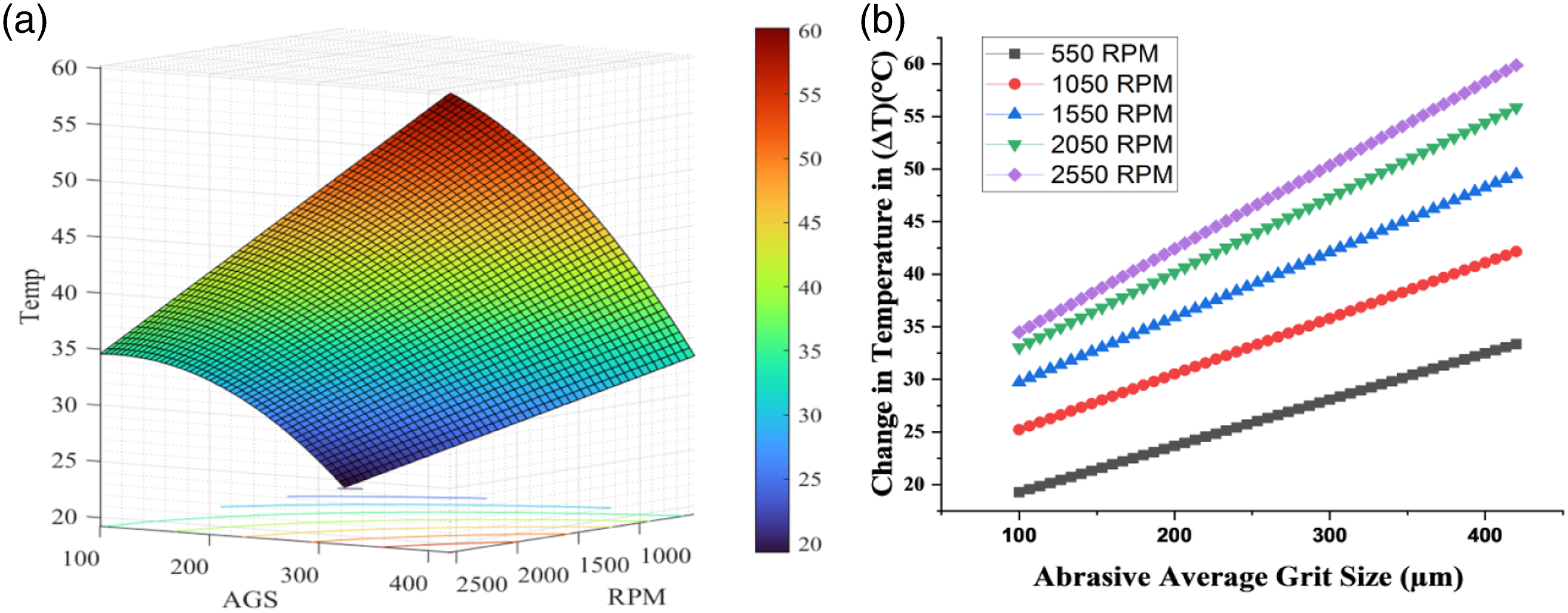
Figure 9 presents the interaction plot between the feed rate and rotational speed. It can be noted from Figure 9 that temperature increased with an increase in the feed rate and rotational speed. This is due to the rise in MRR coupled with the generation of more frictional forces at higher MRR.
The interaction plot between the abrasive average grit size and rotational speed is shown in Figure 10. It can be noted from Figure 10 that temperature increased with an increase in the grit size and rotational speed of the tool. An increase in grit size leads to an increase in the contact area between the tool and the workpiece. By this, more heat is generated due to an increase in frictional forces. Further, this effect becomes more pronounced at higher rpm because of more interaction between the tool and workpiece per unit of time.
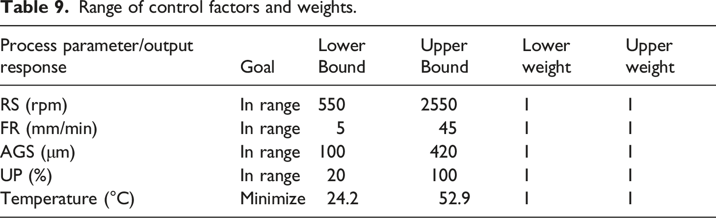
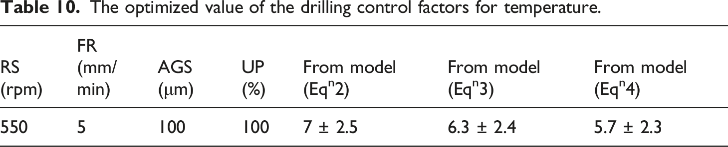
Optimization of input variables for change in temperature
Range of control factors and weights.
The optimized value of the drilling control factors for temperature.
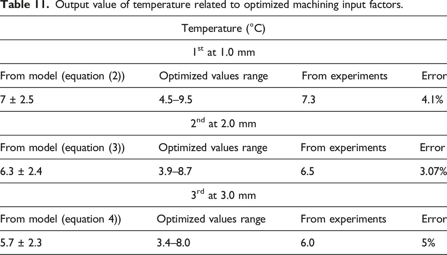
Output value of temperature related to optimized machining input factors.
Micromorphology at the drilled edge site
With the optimized drilling parameters presented in Table 10, conventional and rotary ultrasonic-assisted drilling of CFRP composite was performed to observe micromorphology at the drill site. During conventional drilling, no ultrasonic power with a conventional twisted drill bit was used. Scanning electron microscopy (SEM) is used to monitor the effect of various drilling methods on polyetherimide composite surfaces. Different micromorphology and heat-accumulated zones were observed at the drill edge site by drilling techniques as presented by SEM micrographs in Figure 11. With the conventional drilling of CFRP composite, a heat-accumulated zone or thermally damaged composite surface was observed as illustrated in Figure 11(a). With the microstructure of the drill edge site, fiber pullout with a delaminated zone was witnessed during the conventional drilling of composite material. This is due to continuous drilling that accumulates heat at the drill edge site which leads to damage to the drilled hole surface. The delamination and fiber pullout that occurs in polyetherimide composites may reject the application of composite material for aerospace and automotive application. Whereas with the rotary ultrasonic-assisted drilling of CFRP composite, no delamination and fiber pullout was witnessed as depicted in Figure 11(b). Due to non-continuous and intermittent contact between the tool and the workpiece surface, heat accumulation at the drill edge site can be minimized. With the ultrasonic vibrations provided during the drilling of composite, thermal damage and heat-affected zone can be mitigated to improve the surface morphology and microstructure of fiber-reinforced composite material. SEM micrographs at the drill edge site during (a) conventional drilling, and (b) rotary ultrasonic-assisted drilling of CFRP composite.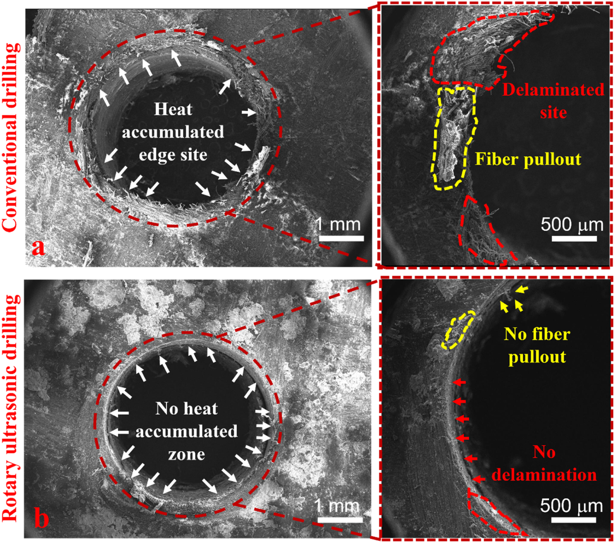
Conclusions
The present investigation is focused on reducing the thermal damage, heat-accumulated defects, temperature elevations and delamination during the drilling of carbon fiber-reinforced polyetherimide (CFRP) composite. The composite material was fabricated using the hand-laying technique and compacted with a power press. For reducing the temperature rise at the drill site, non-conventional advanced machining of rotary ultrasonic drilling (RUD) is leveraged. The influence of various drilling parameters such as rotational speed, feed rate, abrasive grit size, and ultrasonic power was observed on the temperature elevations. The diamond-impregnated hollow drill tool with a RUD setup provides intermittent contact between the composite material and the drilling tool that reduces the temperature elevation at the drill site. It was observed that temperature rises with an increase in rotational speed, feedrate, and grit size and reduces with an increase in ultrasonic power. Rotational speed was the most significant parameter with the highest contribution of 42% that affects the cutting temperature during the drilling of CFRP. The thermal damage, temperature elevations, defects, and delamination during the drilling of composite material can be reduced by leveraging the rotary ultrasonic-assisted drilling of fiber-reinforced composites.
Footnotes
Declaration of conflicting interests
The author(s) declared no potential conflicts of interest with respect to the research, authorship, and/or publication of this article.
Funding
The author(s) received no financial support for the research, authorship, and/or publication of this article.