
Abstract
Filament winding method is the most commonly used method to produce profiles with different cross sections as composite product manufacturing. In this method, fiber material is wound with resin at different angles on a mold that has a suitable cross section shape. As a winding strategy, angled and helical winding can be done. Motion planning for this process is done with geodesic and nongeodesic theories. Requirement to use mold in the filament winding method increases the cost. Also, there is an obligation to helical windings. In winding of different layers, 90° angle cannot be given between the layers. To overcome all these constraints, UV curing can be achieved using photopolymer resin and continuous fiber glass fiber with the help of robotic additive manufacturing technology. Toolpath strategies for production has a key role in this work. As a tool path strategy, nonplanar slicing can be done and manufactured composite elbow in angular layers without mold. Then, under favour of 6-axis mobility of the industrial robot arm, layers can be obtained at exactly 90° angle. In addition, in this method, unlike other winding methods, internal voids, i.e. a filling rate, can be given within the cylindrical encircled layers. In order to verify whether the elbows produced with this method meet the requirements of the desired applications in the industry in terms of mechanical properties, at different filling rates (50%, 75%, 100%), winding turns (0 and 1/8), and different fiber densities (45%, 55% and 65%) 90° curved composite elbows were produced and their internal pressure strength tests were tested. Afterwards, an optimization study was carried out with the Taguchi method for the production parameters that will maximize the internal pressure strength. According to the results of the optimization study, it is seen that it is appropriate to choose the printing parameters that will obtain the highest internal pressure strength values for production with this method, 100% fill rate, 65% fiber density and 0° winding angle. The products made of this process have the advantage of easy-shaping, reasonable ratio of axial strength and encircled strength, specification easy-unifying, stable product quality.
Keywords
Introduction
One of the most widely used structural elements are pipes and elbows elements. It is used in different tasks and industries as a structural support element, especially in transportation operations, works with pressurized fluids. 1 These elements are generally produced from different materials, with different properties and geometries, by different methods. Pipes and elbows made of plastic, metal and composite materials are widely used. Nowadays, developing composite pipes and elbows and their production methods. The most common production method for these composite pipes and elbows is the production by filament winding continuos fiber with resin on a mold.2,3
Various pressure vessels, from metal to composite tanks, have been developed over the last two decades primarily for weight savings and higher pressure strength values. Most advantageously, composite material pressure vessels can affect the weight savings of fuel gas tanks by up to 75% compared to metallic material vessels. As a result, the production of composite pipes and elbows with FW technology has increased. Many design and manufacturing challenges still need improvement in relation to the different process factors involved in winding technology. Therefore, when designing and manufacturing a product in the filament winding method, it is necessary to understand and find solutions to the different process parameters, their combined effects and the associated challenges. 4 To reveal the shortcomings and limitations of the original filament winding method, even for each minor revision, a separate mold is required, the difficulty of creating a winding trajectory for production, and the inability to adjust the winding direction symmetrically when the form to be produced is angled. There are movable axis constraints that will allow these rotational movements of the production machines. Removing the manufactured product from the mold becomes impossible when the product is complex.5–8
If the studies done to solve these constraints and boundaries are examined, this applied fiber winding strategy is commonly used in computer aided manufacturing programs to help produce a specialized toolpath. However, it has limited production parameters such as not fitting every geometry, mold requirement and winding angle. 9 There are special two or 3-axis winding machines developed for filament winding. 10 Due to the low efficiency and low production flexibility of the filament winding machine, a robot-based control systems that control the fiber winding motion trajectory for elbow and pipe elements are widely used today. Robot-based filament winding systems have many advantages such as flexibility, multiple degrees of freedom, and wide range of operations. 11 To demonstrate the advantages of multi-axis 3D printing systems, work has been done by integrating a 3D printing system into a six-degrees-of-freedom industrial robot. The robotic-assisted 3D printing system makes it possible to print on inclined planes, which cannot be achieved with a conventional 3D printer, and increases production quality. In addition, robotic coding is used instead of the Gcode strategy to reschedule the Gcode printing method, resulting in faster and smoother movement compared to traditional 3D printing. 12
Especially on the fiber winding method, many studies have been carried out to determine the motion planning methods and effective winding parameters for composite elbow winding. This is due to the curved structure of the elbow geometry. Motion planning methods are being developed for nonaxisymmetric structures emerging.13,14 If it is necessary to list the most important benefits of providing a 90° and 0° fiber winding angle in production, when the fiber winding direction is oriented in the load direction, it provides the strongest and most rigid mechanical properties. In pipes and elbows, it also contributes to flexural strength as a result of winding along the length of the pipe or elbow.15,16
In order to examine the mechanical properties of composite elbows under operating conditions, to examine their behavior under internal pressure strength test and bending moment. As a result of these examinations, the production method and the compatibility of the materials used with the operating conditions can be tested. However, it has been reported that approximately 300 MPa tensile strength and 450 MPa bending strength can be obtained in the study carried out to reveal the mechanical strength limits of the products produced by this method. 17
In a study on this subject, the behavior of fiber epoxy composite elbows under internal pressure and bending moment is discussed. Elbow samples were produced from woven glass fiber fabric and in epoxy matrix structure with 50% volume ratio. As a result of the tests, it is reported that the environmental stress for woven fiber composite pipe is almost (14%) higher than the axial stress. In the case of internal pressure alone, the maximum internal pressure was achieved almost (115%) higher than the internal pressure combined with the bending moment. 18
This research aims to examine the internal pressure behavior of composite elbows. For this aim, knitted preforms were used in the CMC-330-TC Flat knitting machine. Also, non-woven fibers were used. For the manufacture of composite elbows, the bladder molding technique was used. The produced products were subjected to internal pressure test. Experimental results reported that the integrated composite elbow is resistant to higher hydrostatic pressure. Thus, integral braided elbows were damaged at 12.5 bar pressure, while non-integrated elbows were damaged at 9.5 bar pressure. 19
This study reports the results of the experiments obtained from the internal pressure and bending tests of e-glass reinforced polyester composite elbows. Fibers to be produced as fiber glass chopped yarn and woven roving fabric were selected. Results show that the stiffening effect of glass fiber reinforced composite elbows occurs with sequential bending cycle loads and cyclic internal pressure application. 20
The purpose of this research is to examine the behavior of carbon epoxy composite elbows under internal pressure and bending moment. For the production of curved pipes, epoxy matrix material with 50% fiber mass ratio in woven roving (Matt) carbon fiber composite material was used. As the production method, vacuum infusion technique was used. It has been reported that circumferential stress and elongation are almost (13%) and (18%) greater than axial stress and elongation, respectively. In the case of internal pressure alone, the maximum internal pressure was measured almost (52%) higher than when the internal pressure and bending stress were combined. 21
In this research, the behavior of composite elbows under internal pressure is discussed. Two groups of materials are used in the manufacture of elbows. The first consists of woven roving (Matte) carbon fiber and epoxy matrix. The second one consists of woven roving (Matt) fiber glass and an epoxy composite matrix with a volume ratio of 50%. The production was made by vacuum infusion technique. It is disclosed that the circumferential stress for woven roving carbon composite elbows is almost (4.5) times greater than for woven roving fiber glass composite elbow. The internal pressure strength of woven roving carbon composite elbows has been reported to be almost (3) times greater than woven roving fiber glass composite elbows. 22
In all the studies examined, either manual production or semi-automatic composite elbow production was discussed. Automated production of composites is handled by filament winding method. However, mold need and production parameters and motion trajectory problems prevent the development of production with the method. To overcome these limitations, robotic 3D printing methods are developing composite production. Many inventors in this field have developed more than 250 patents in recent years.23–36
The most important thing that motivates the work is the use of robotic 3D printing method, which helps to provide a fully automatic moldless production. Here, with the advantage of robotic 3D printing, six axis toolpath strategy can be determined and production can be made in different layers as desired without geometric constraints. Another important issue is which printing parameters should be used in composites produced by robotic 3D printing method, which can be considered as a different method for products that are difficult to manufacture due to the nonaxisymetric geometry, and the composite elbows produced with this method should be able to provide the desired properties under operating conditions. In order to confirm the desired properties of the composite elbow, the internal pressure test was applied and the effective 3D printing parameters were investigated experimentally and statistically according to the data obtained from this test.
Material and Method
In this study, composite 90° elbow was produced by robotic 3D printing method. In order to achieve this, first of all, the selected materials and production method should be mentioned. Since similar mechanical properties are required with industrially produced equivalent composite elbows, first of all, the materials used should be the same. For these reasons, a composite material with a continuous glass fiber reinforced photopolymer resin matrix was chosen. For the 3D printing of this material, a combination of Fused Deposition Modeling (FDM) and Stereolithography (SLA) methods was preferred. Because only in this way, a product equivalent to other composites produced in the market can be obtained.
First, considering the production method, the liquid resin is positioned on the robot arm so that it flows under the influence of gravity. Then, a nozzle to carry out the production was added to the robot arm. In addition, continuous fiberglass spools are positioned on the robot arm and are moved to pass through the nozzle. Resin, which can flow with the effect of gravity, is connected to the nozzle before the exit of the nozzle. Thus, the resin and fiber are mixed without leaving the nozzle. As soon as it is deposited out of the nozzle, Ultra Violet (UV) curing light is given from four directions to the area where the photo-cured resin is poured. In this way, composite production can be realized with robotic 3D printing method.37–41 Finally, a motorized turntable was produced and fixed on the robot’s table, since 360° around the elbow were required in the production system. The elbow was produced on this turntable. Figure 1 shows the system arranged for robotic 3D printing composite. The system arranged for robotic 3D printing composite.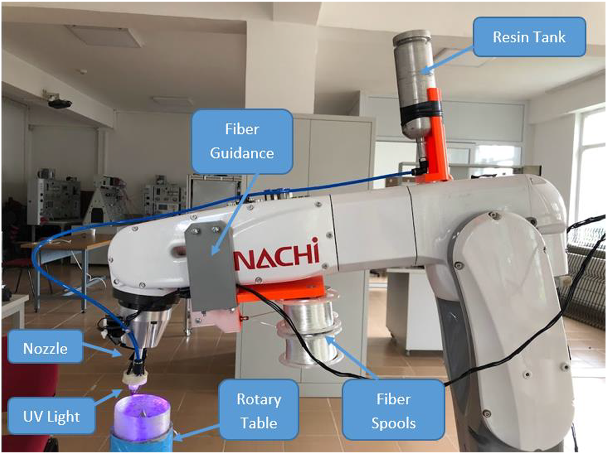
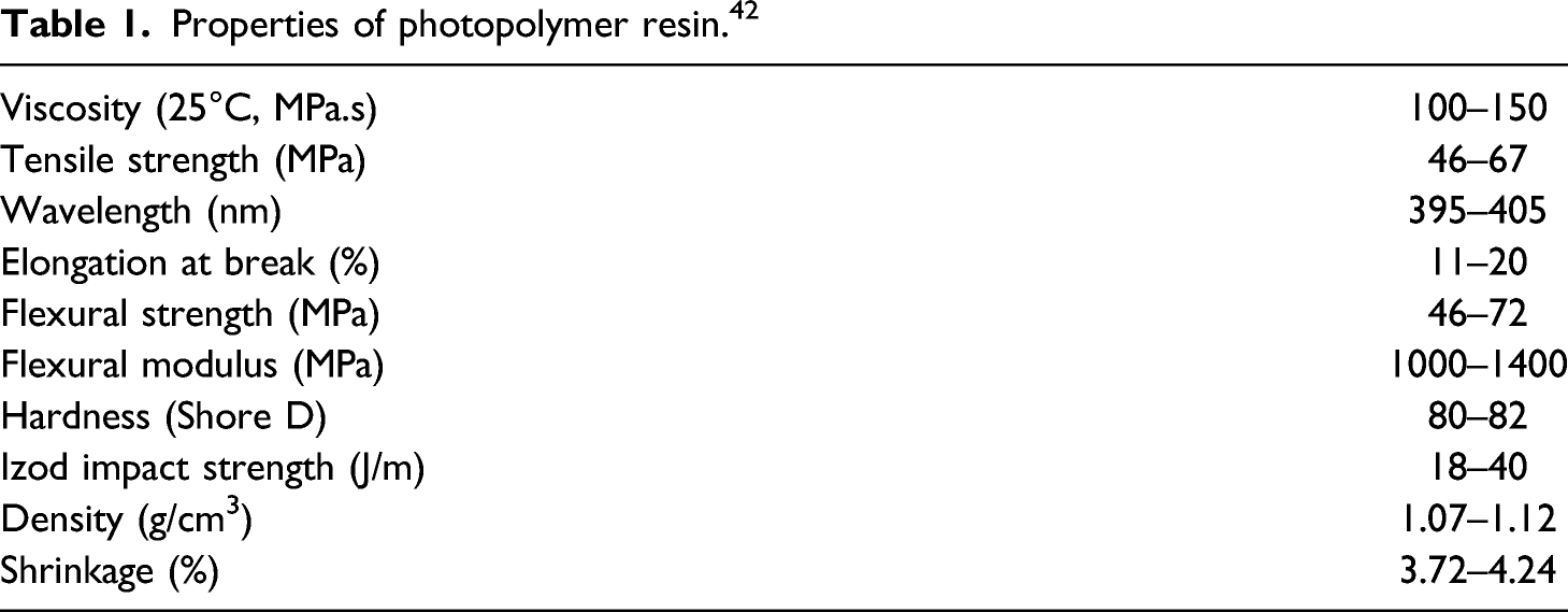
Properties of photopolymer resin. 42
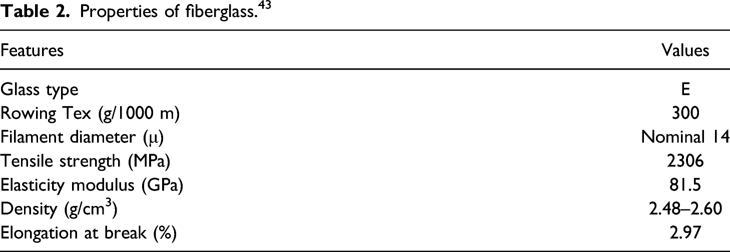
Properties of fiberglass. 43
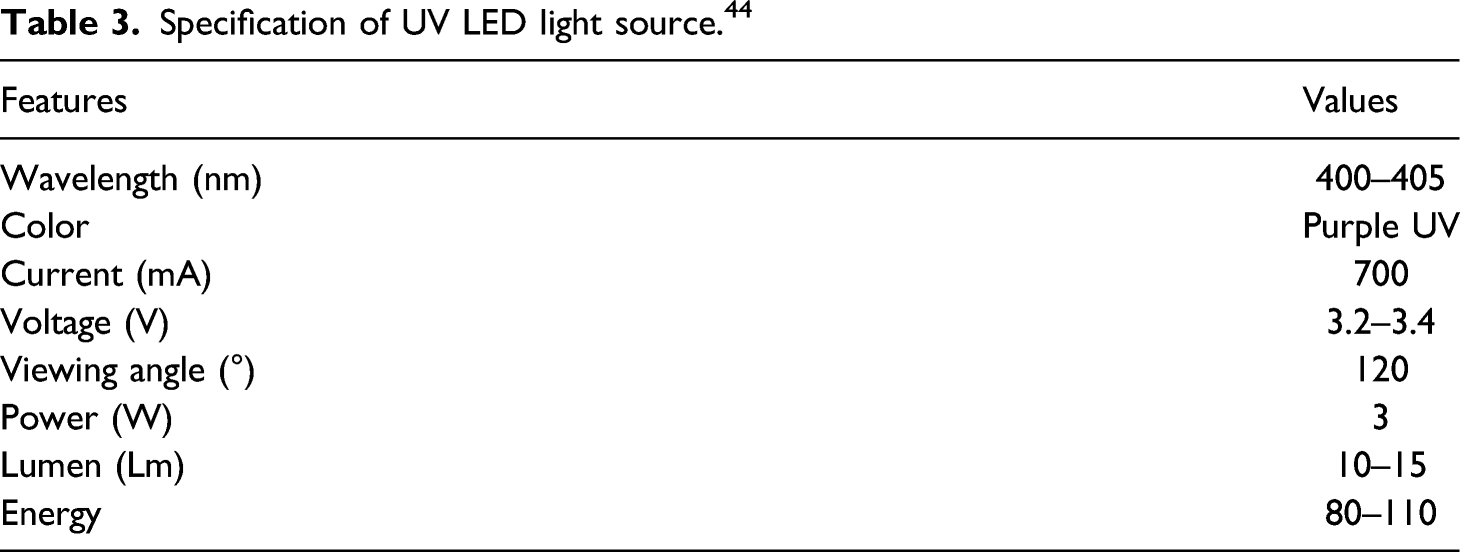
Specification of UV LED light source. 44
In the study, firstly, the dimensions should be determined for 90° composite elbows. When determining dimensions, EN 10253 and AWWA C950 composite pipe and elbow standards were examined and the commonly used inner diameter of 63.5 mm (2.5 inches) and a radius of curvature of 95.25 mm (3.75 inches) were determined.
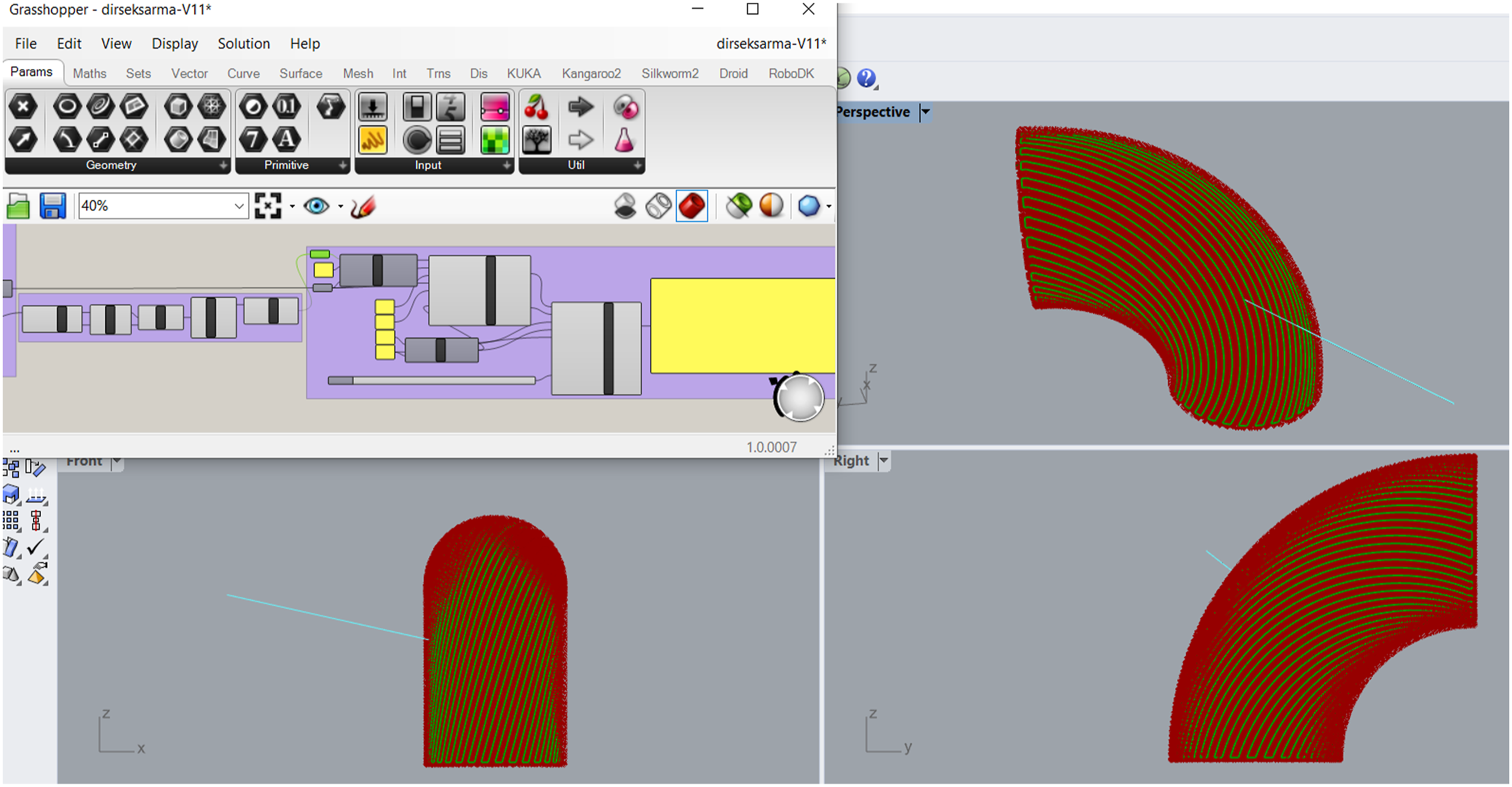
The toolpath for robotic additive manufacturing required for production was created with the help of Rhinoceros 3D drawing program and Grasshopper parametric design plugin. This created toolpath can be handled in three groups. 90° composite elbow will consist of four layers in total. The first of these will create the main layer. Then, flat winding and helical winding layer will be realized as if it is wound on the die. After straight winding, the third layer will be produced at an angle of 90° as in the filament winding method with a single helix from the outside, and finally, the fourth layer will be finished by winding straight along the elbow axis again. In the helical winding, after the first layer is produced, the second and third layers are wound right and left with opposite helix angles, and then the last layer is wound as a single helix from the outside. The first layer is made to form the main line of the elbow instead of the mold. The main element here is angular slicing. The elbow is angularly divided into segments, and at this angled circles are translated into production code as layers. Figure 2 shows a picture of the toolpath creation process for the first layer. Creating a toolpath for the production of the first layer.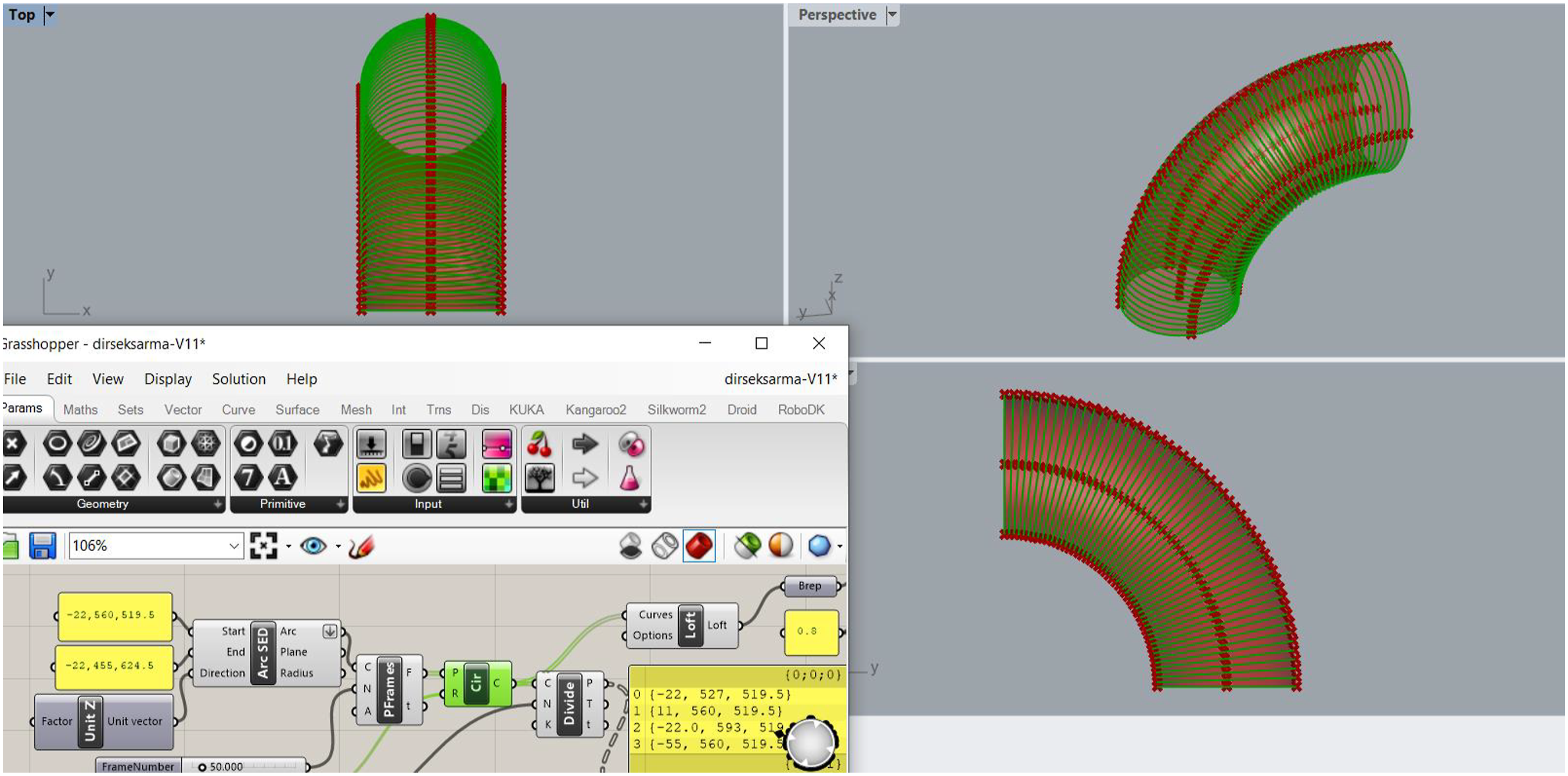
Then, as the second part of toolpath creation, straight and helically angled curves were created to wrap around the first fold elbow, which was created similar to filament winding from the outside. The derivation of these curves is given in Figure 3 and Figure 4. Creating the toolpath to wind straight for the intermediate layers. Creating the helically winding toolpath for the intermediate layers.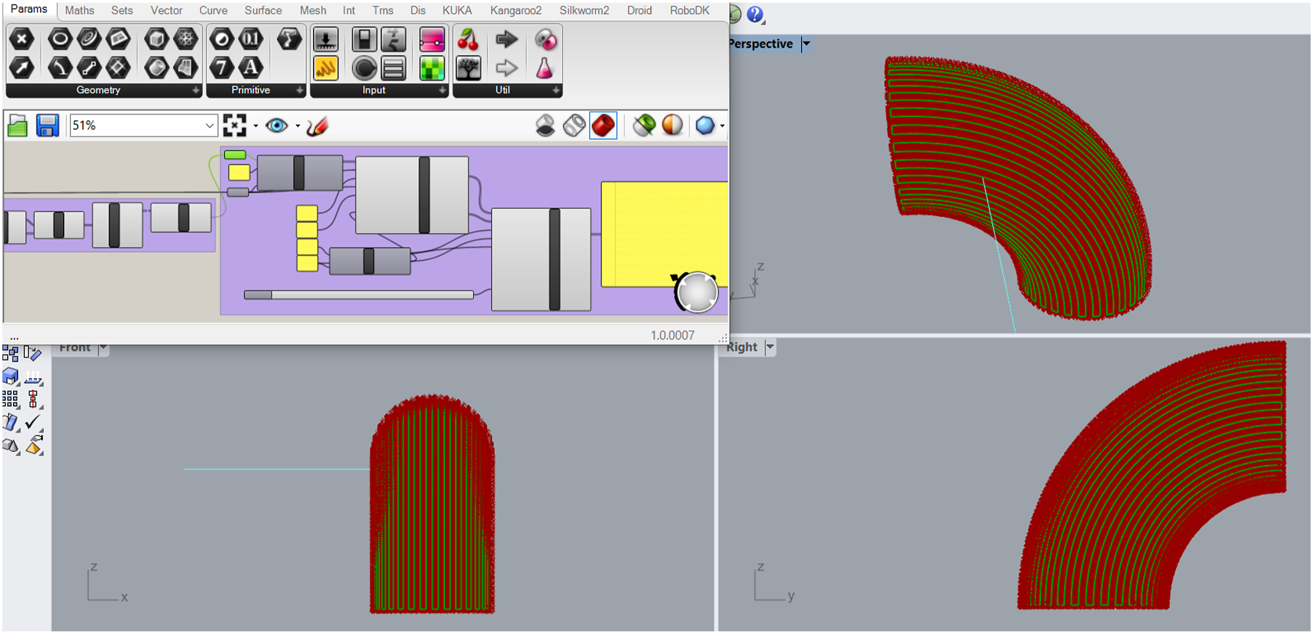
Then, a single helix curve, similar to the filament winding strategy, was created to wind the elbow with the helix toolpath for outermost winding. Figure 5 gives a picture of this extracted tool path. Creating the toolpath for the outer finishing winding.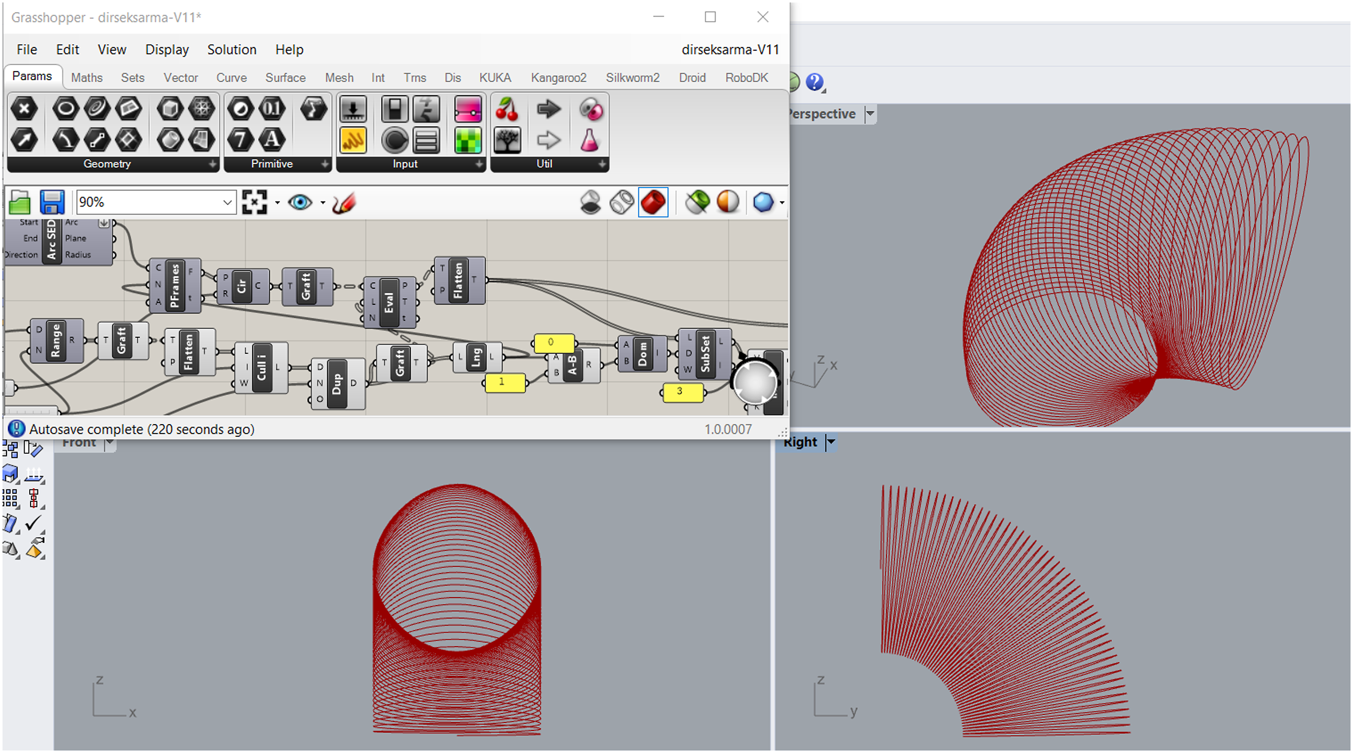
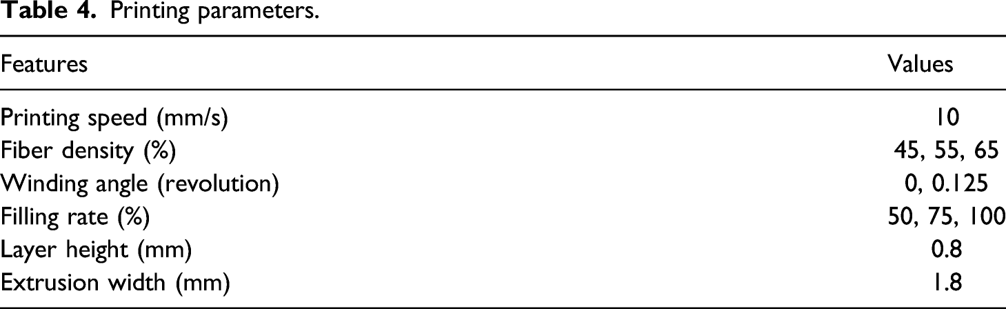
Printing parameters.
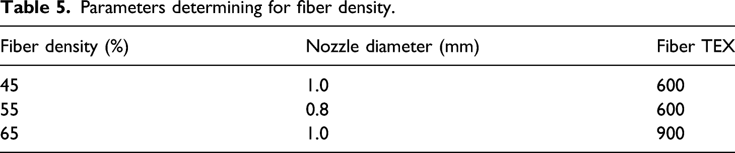
Parameters determining for fiber density.
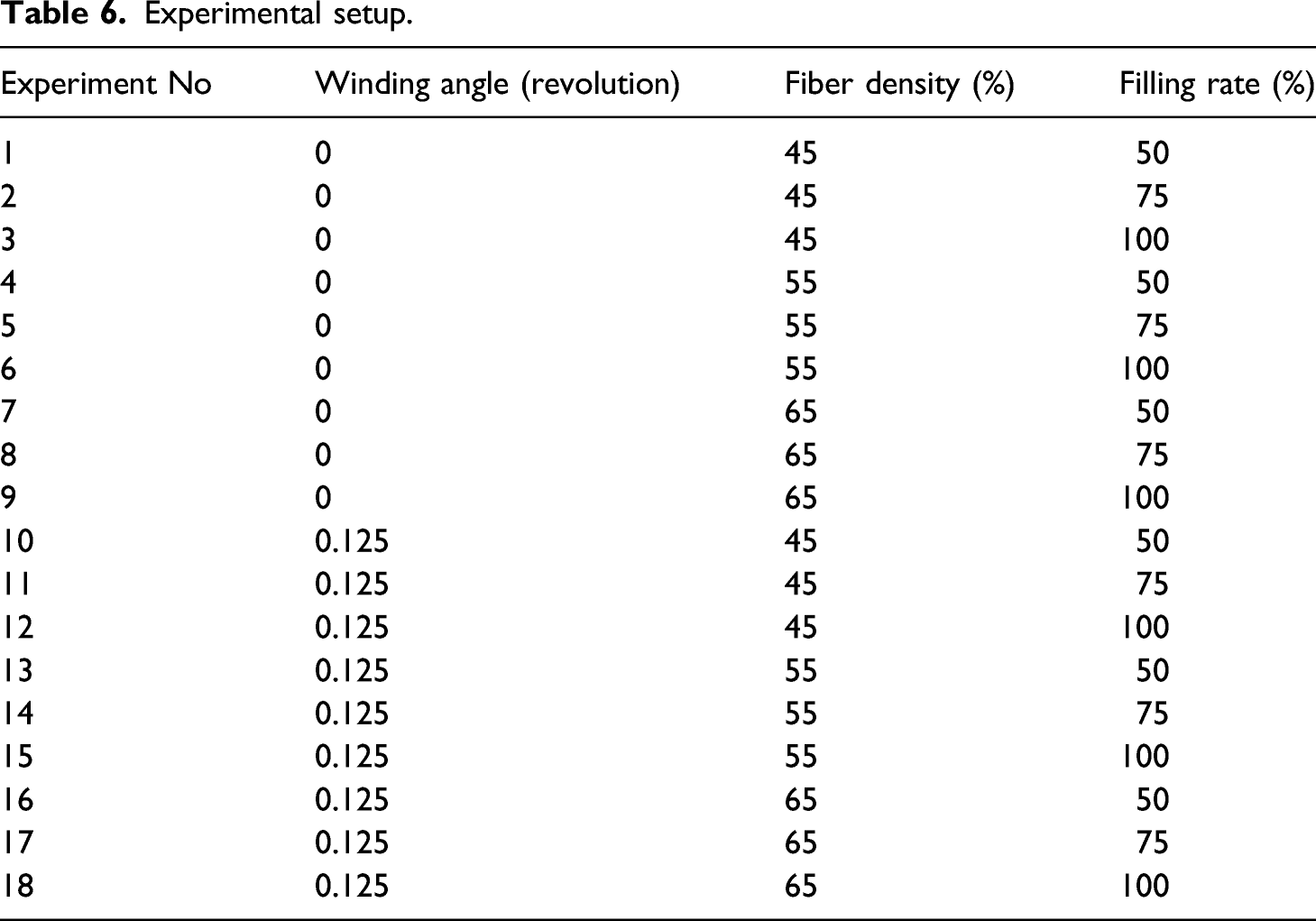
Experimental setup.
In Figure 6, the 90° composite elbow part where is formed as the first layer is illustrated. As can be seen here, elbow production was performed on the turntable. Angular winding in slices was carried out without a mold. Production of the first layer of 90° composite elbow.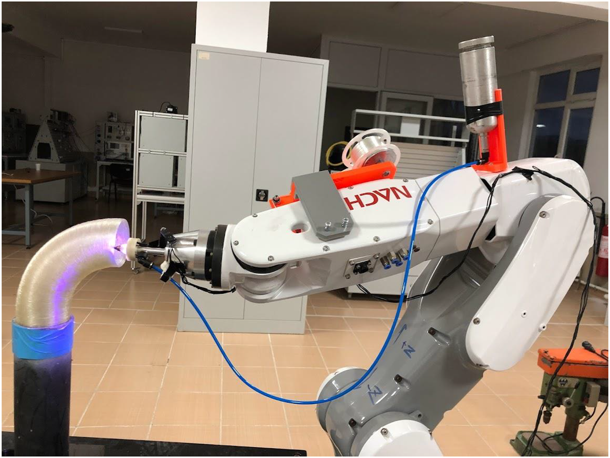
Then, on this first layer produced without a mould, flat winding at 100% filling rate (on the left) and flat fiber winding at 75% filling rate (right) are given as examples, as seen in Figure 7. Here, after 180° winding due to the movement restriction of the robot arm, the part connected to the turntable is rotated 180° and the opposite side of the elbow is processed. In this way, intermediate layers can be created as desired with 180° winding codes. Production of flat winding at 100% filling rate (on the left) and flat fiber winding at 75% filling rate (right).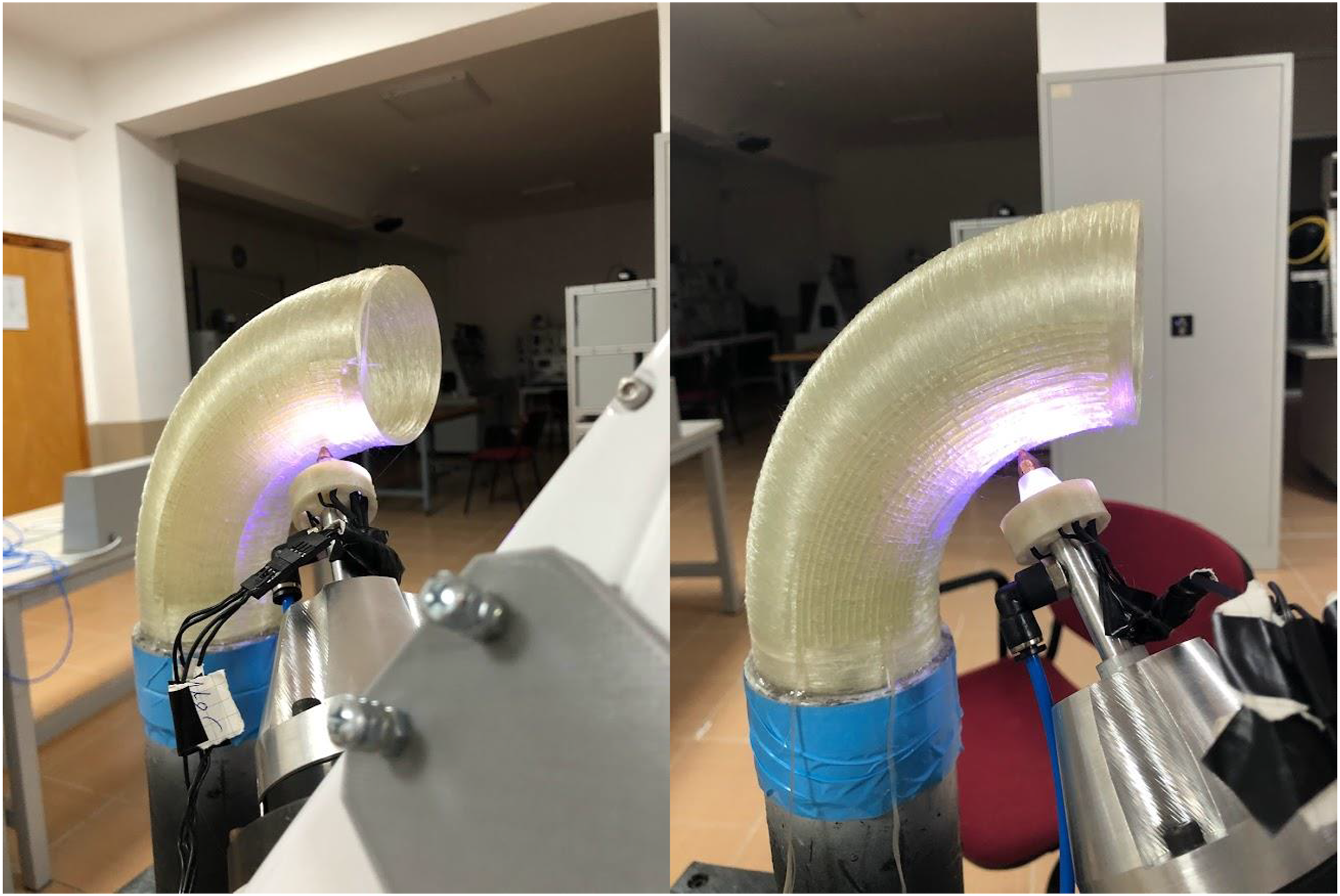
As seen in Figure 8, 0.125 turns of helical winding at 100% fill rate (on the left) and 0.125 turns of helical fiber winding at 50% fill rate (on the right) are given as an example. In the same way, interlayers can be created as desired with 180° winding codes. Production of 0.125 turns of helical winding at 100% fill rate (on the left) and 0.125 turns of helical fiber winding at 50% fill rate (on the right).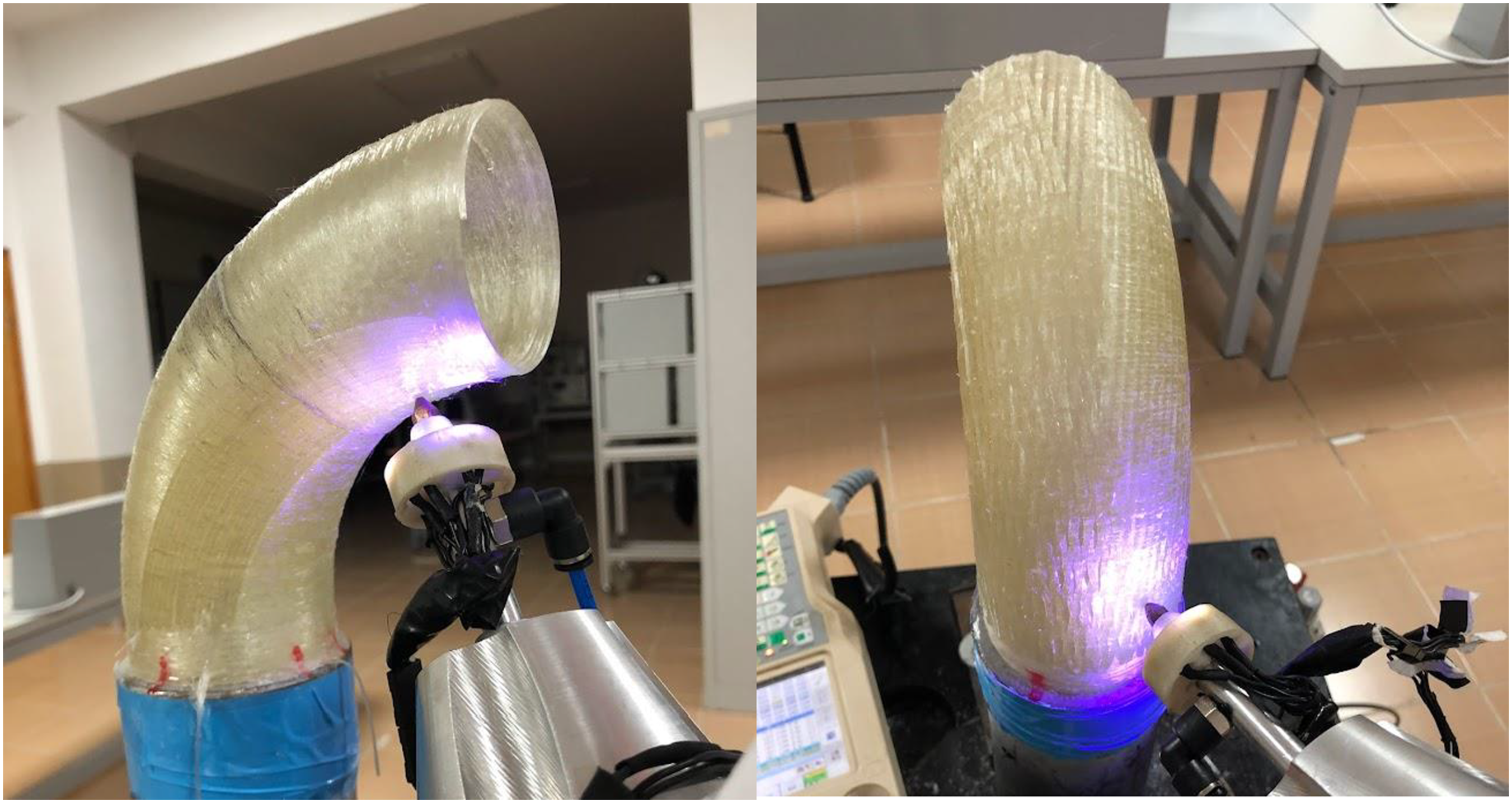
Then, our turntable, which was produced for angular rotation control with the help of a stepper motor, was synchronous with the robot arm in order to wind the outer helical layer due to the movement restriction of the robot arm, and the last layer was wound by turning the elbow in a single helix form from the outside of the 90° composite elbow. Figure 9 shows a picture of the helical winding of the outer layer (left). Figure 9 shows the motion control circuit for the stepper motor (right). Helical winding of the outer last layer (left), rotation control circuit of the turntable (right) for this robotic 3D printing composites.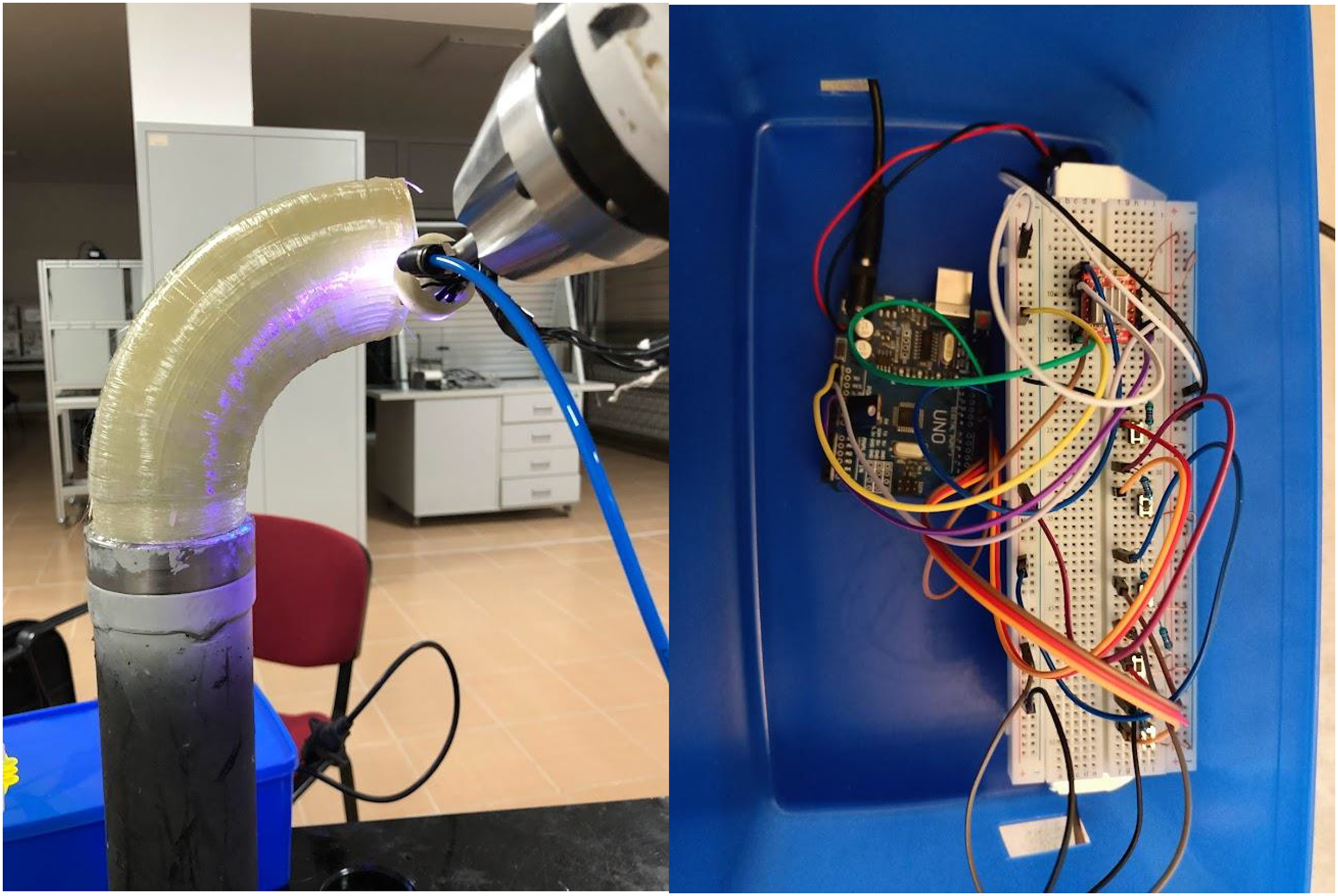
After the productions are carried out, the open parts of our 90° composite elbow must be closed in order to perform the internal pressure strength test. For this closing process, a mold was produced and an elbow and a connecting element for pressurized liquid inlet were placed in this mold and casting was made from epoxy resin. Figure 10 shows the placement of elbows in the molds (left) and the composite elbow (right) ready for internal pressure testing. Placement of elbows in the molds (left) and ready composite elbow for internal pressure testing (right).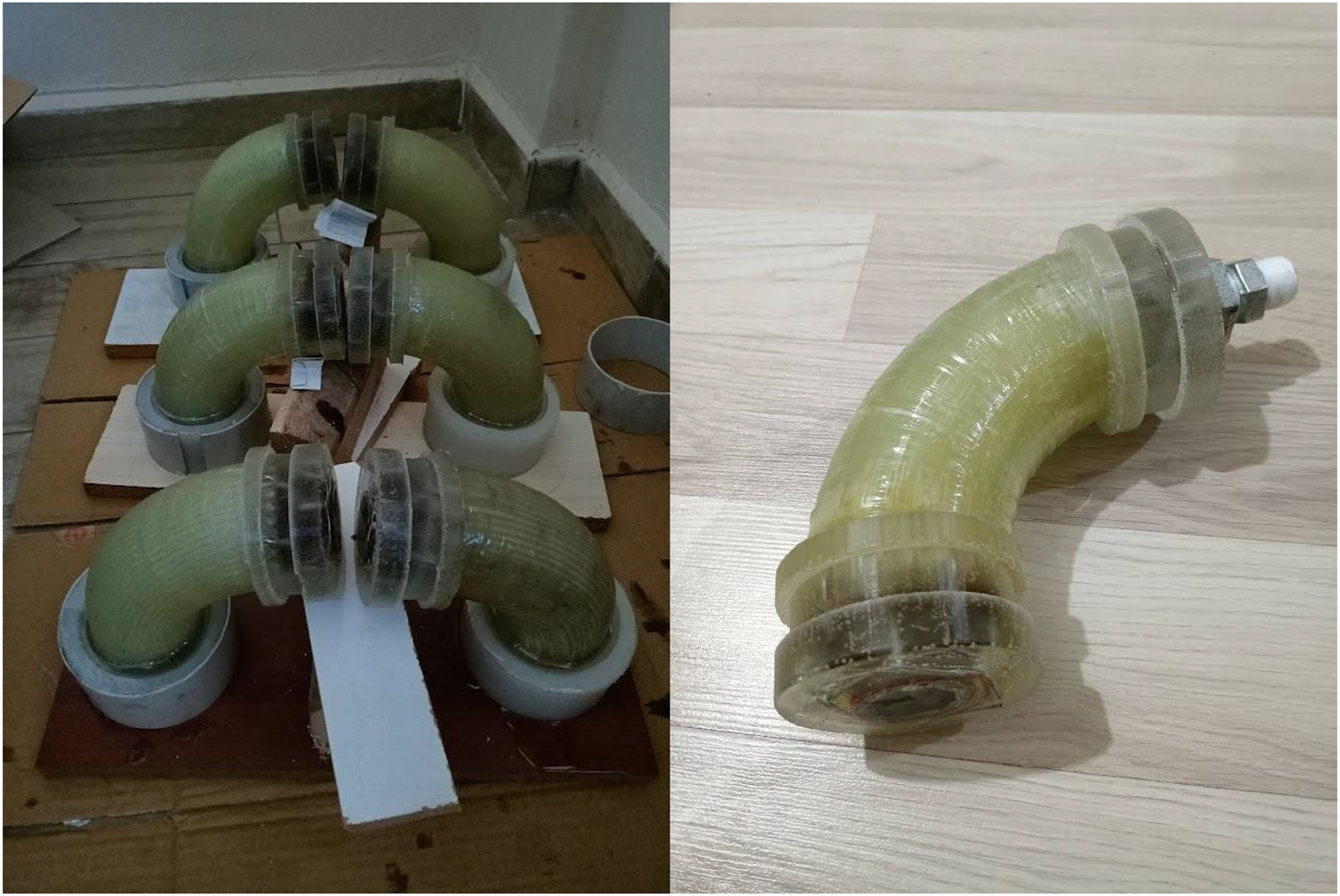
In Figure 11, an image of the internal pressure strength test device and the test performed in the autoclave oven to prevent any accident is given. Three samples produced from each parameter were damaged under internal pressure and the average of these values was recorded. Internal pressure strength test.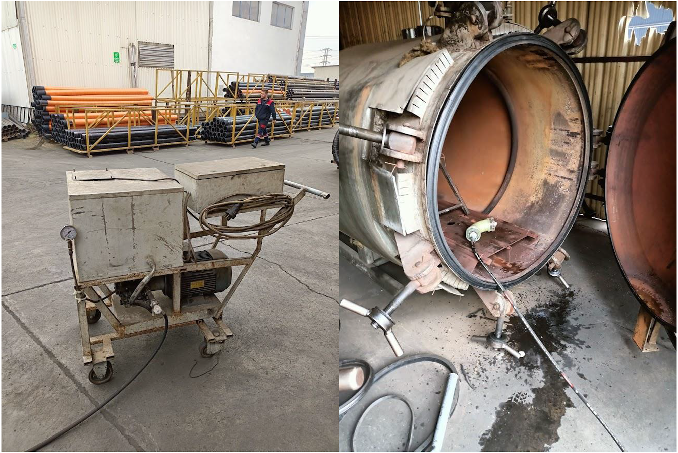
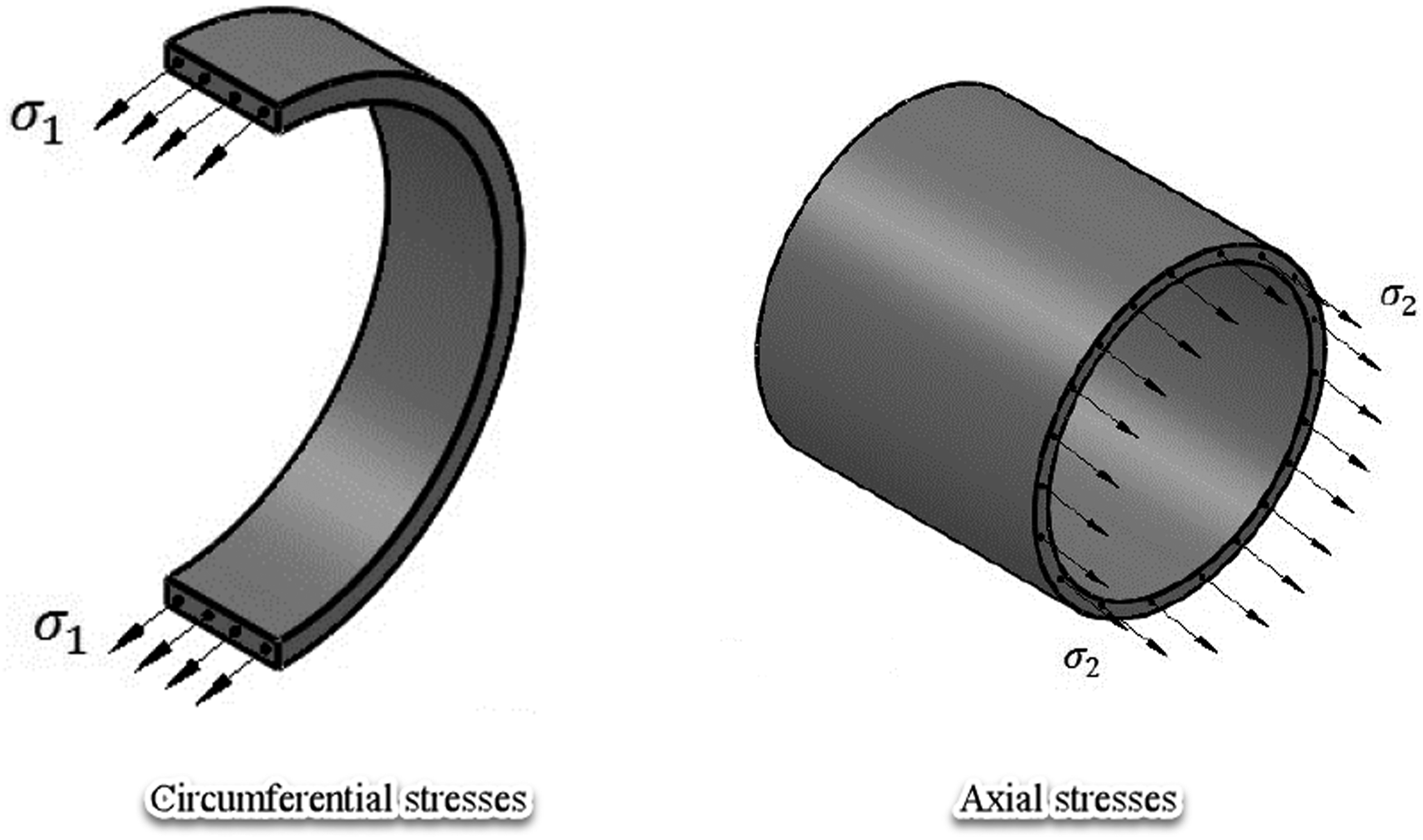
In thin-walled vessels, radial stresses are neglected as they are much lower than other stresses on the outer wall surface.
46
The circumferential ( Stresses in pressure vessels.
47
In order to specify the effects of printing process parameters on internal pressure strength properties (circumferential stress and axial stress), optimization was carried out with the Taguchi method. Analytical methods such as analysis of variance (ANOVA), regression analysis, Signal/Noise (S/N) ratio, Taguchi (L18) optimization method were used for statistical study to determine the effect of printing process parameters on axial strength and circumferential strength. Three different effective process parameters used; Fiber density (45%, 55% and 65%), filling rate (50%, 75% and 100%) and winding turn (0 and 0.125 revolution) were determined. By keeping the other printing parameters in the same condition as the fixed parameters, 90° composite elbow specimens were produced for all parameters.
In this context, ANOVA with a safety factor of 95% (α = 0.05) was applied to the test results and the effect levels of the parameters on the internal pressure strength were determined. Taguchi L18 methodology was performed for optimization of process parameters.
Taguchi’s “biggest is better” criteria given in equation (3) is used in the optimization of printing process parameters. While applying the Taguchi method, it converts the target function to the signal/noise (S/N) ratio to specify effect of these parameters at different levels. The S/N ratio is specified with the help of the optimum levels of printing process parameters.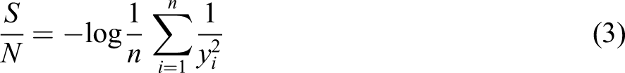
Results and Discussion
Experimental and statistical test results.
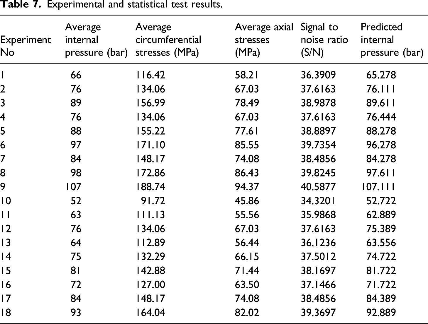
As can be seen from Table 7, the highest compressive strength was measured as 107 bar for Experiment nine. The lowest internal pressure value was measured as 52 bar for Experiment 10. Glass reinforced plastic pipes are classified in 5 (five) nominal pressure (PN) groups as standard: PN 4 bar; PN 6 bars; PN 10 bar; PN 16 bar; PN 25 bars. However, in accordance with the standards, it is produced to withstand internal pressure up to 35 bar as the pressure class to be forced at the maximum. 48 As a result of the experiments, the minimum pressure value of 35 bar, which is required to be provided in accordance with pressure classes and production standards, was obtained in Experiment 10, which has the lowest internal pressure resistance of 52 bar.
As we will see here comparatively, fiber density and filling ratio are largely effective on internal pressure resistance value of the elbows. It can be thought that winding angle has little effect on the internal pressure strength, but here a significant change in internal pressure strength is observed, although close angles are selected. These changes are even more effective in increasing winding angles.
Statistical results from ANOVA analysis.
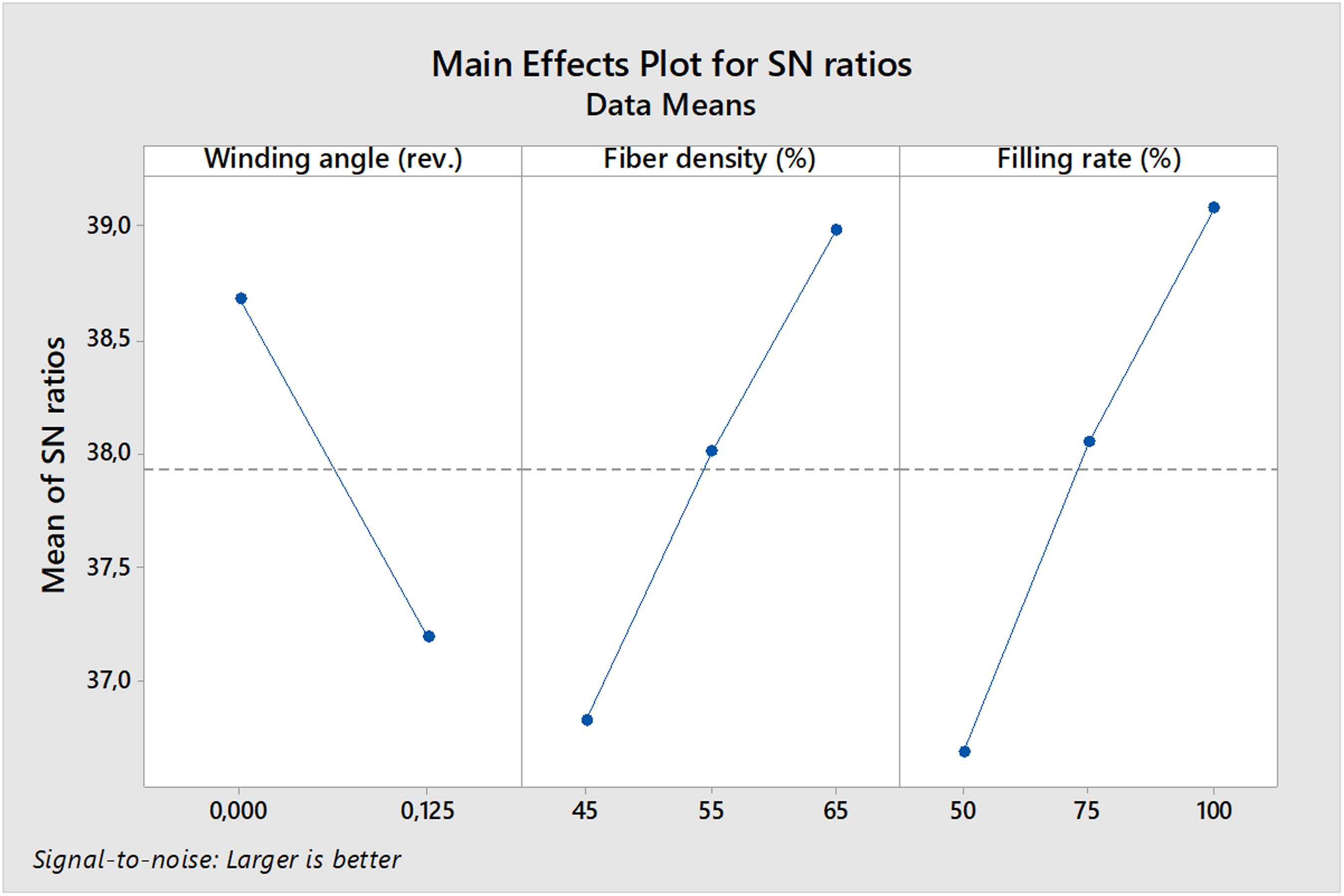
Main effects graph for S/N ratios of each parameter level.
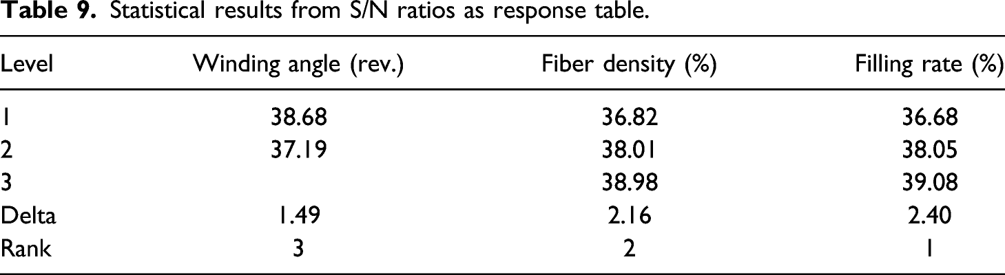
Statistical results from S/N ratios as response table.
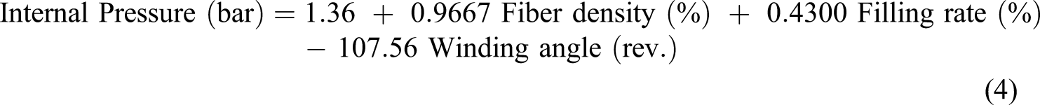
With the help of equation (4), effective parameters for the desired internal pressure resistance values can be calculated or if the predicted production parameters are used, how much internal pressure resistance can be obtained.
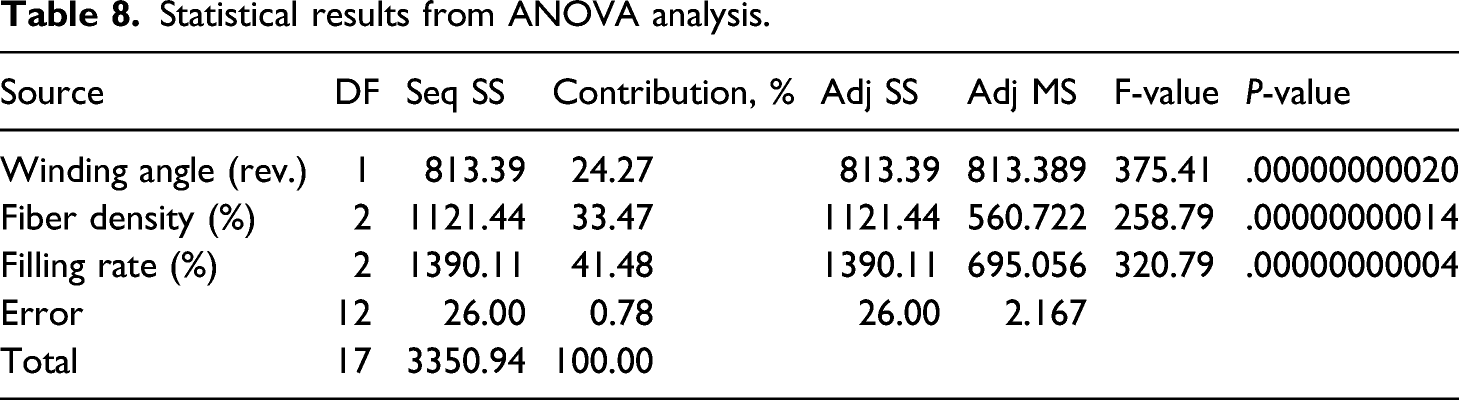
When the analysis of variance table in Table 8 is examined, it is seen that the statistical calculations in the p-value column are sufficiently sensitive. The effect of each of the printing parameters on the internal pressure strength value is given as a percentage. Here, it is observed that the most effective parameter is the filling rate as 41.48%. Other effective parameters were calculated as fiber density 33.47% effective and winding angle 24.27% effective, respectively.
Figure 13 gives main effect graph of S/N ratio values. In Table 9, the values corresponding to the levels of effective parameters of the S/N values in this table are given. From here, the effective levels for the internal pressure resistance value are determined. Thus, it can be said that the best strength is achieved at 0 turns winding angle, 65% fiber density and 100% filling ratio.
Figure 14 shows the statistical calculations and the distribution of the data there. As can be understood from this, the reference curve chosen for the distribution is close to the set of points. Normal probability plot of statistical results.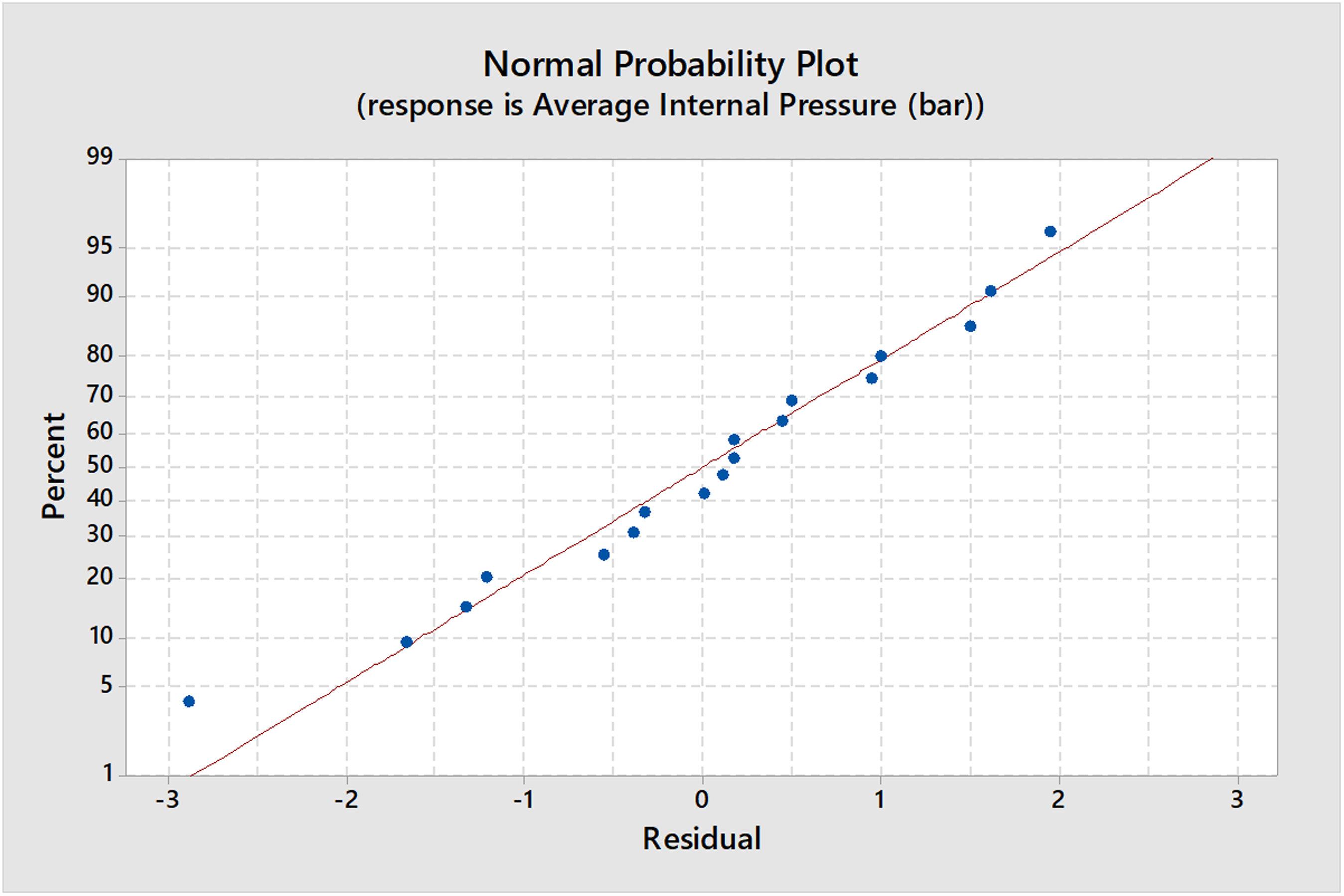
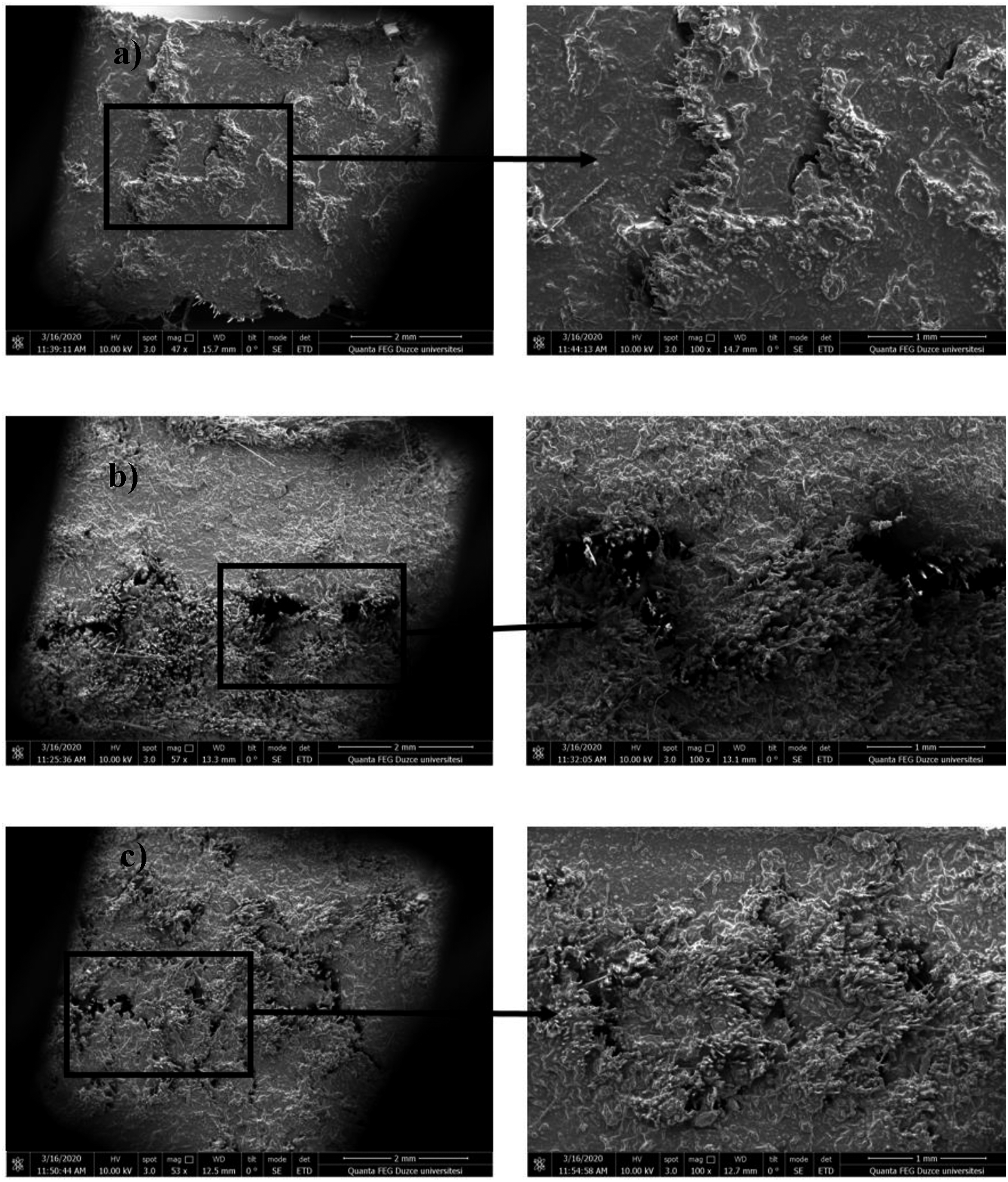
Estimated pressure values were calculated with a margin of error of 0.78%. This margin of error allows us to calculate with equation (4) without making preliminary experiments when choosing parameters for many jobs. Figure 15 shows a damaged elbow after the internal pressure strength test. Elbow and connection parts are combined with epoxy resin in the form of a thick casting and sealing is ensured. The elbow is placed 20 mm into the epoxy resin. The damaged area is the upper level of the epoxy resin poured inside the elbow. 10 mm of the 20 mm length remaining in the epoxy resin remained in the ruptured part. As can be seen here, all elbows are damaged in a similar way. This damage area indicates to us that the damage has occurred with the effect of axial stress. The damage and the area of damage formation in this test is consistent with the literature.46,47 As in the 3D printing method, damage has occurred by separating the fiber fibers between the parallel layers. Image of the composite elbow after internal pressure test.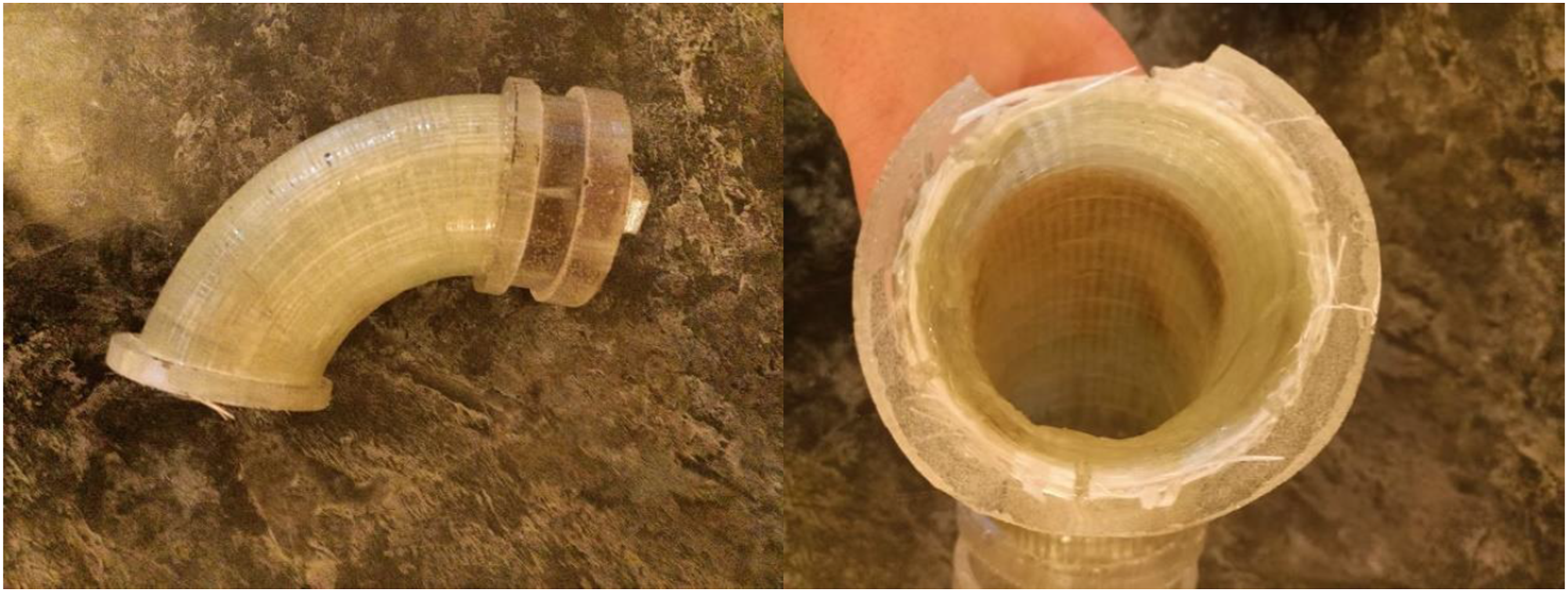
When internal pressure strength test and statistical results are examined, as the fiber density increases, the internal pressure strength increases proportionally. Likewise, as the filling rate increases, the internal pressure resistance values increase. If the relationship between fiber winding and internal pressure resistance is examined, the resistance is highest in zero turn winding, that is, in the outer winding perpendicular to the inner layer, compared to the internal pressure. In the literature, similar results are obtained in the manufacture of composite elbows made with other methods. As the winding turn or angle approaches zero, the strength values increase. When the winding turn is zero, it is maximum. The main point here is that it is not possible to get exactly zero in this angle mold winding method, since the mold must be connected to an axis. Therefore, it is stated in the literature that the strength increases as the winding angle approaches zero.49–56
If we look at the previous studies in the literature for laminar production other than elbow production, it can be said that the production with this method is suitable for use in elbow elements as well as laminar and other products. In Figure 16, microstructure images are given for the production made at 45%, 55% and 65% filling rates. In addition, according to the ASTM D3039 standard, the tensile strength is up to 323 MPa. According to ASTM D256 standard, flexural strength up to 450 MPa can be obtained.17,44,45 Micrograph of microstructure for Robotic additive manufactured composite products (a) 1.0 mm nozzle diameter and 600 tex fiber density, (b) 0.8 mm nozzle diameter and 600 tex fiber density, (c) 1.0 mm nozzle diameter and 900 tex fiber density.
17
Conclusion
As a result, composite 90° elbow was produced by robotic 3D printing method as an alternative to fiber winding methods. Production was carried out without need for a mold. Thus, fiber orientation between the layers of the elbow can be carried out exactly at an angle of 0–90° to the elbow. Outlined results of the study are given below. • For robotic 3D printing in six axes, a toolpath creation process that generates slicing or production code has been performed. • A filling structure is formed for the helical external winding. • The angle of this created helical winding can be changed as desired and a porous structure can be given during the winding at the desired filling rate, as in the 3D printing method. • The minimum pressure value of 35 bar, which is required to be provided in accordance with pressure classes and production standards, was obtained all of experiments. 100 bar internal pressure strength value can be obtained and can be preferred industrially in many areas. It is suitable to be preferred especially in areas that will work under corrosion and in aviation and space sectors where lightness is desired. It can provide a mobilized solution in the repair works of composite pipes and transport systems in the field. • Different fiber supports can be adapted. It is possible to reach higher strength values by diversifying and improving the materials used. • Different filling structures can also be developed and applied rather than helical winding filling structure. • The most effective parameter on internal pressure strength properties is filling ratio and winding angle parameter can be said to have the least effect on internal pressure strength properties. • Different internal pressure strength properties can be obtained from the statistical equation (4). With this equation, internal pressure strength values can be calculated for variable robotic additive manufacturing parameters. This parameters can be regulated for best internal pressure strenght.
Footnotes
Declaration of conflicting interests
The author(s) declared no potential conflicts of interest with respect to the research, authorship, and/or publication of this article.
Funding
The author(s) received no financial support for the research, authorship, and/or publication of this article.