
Abstract
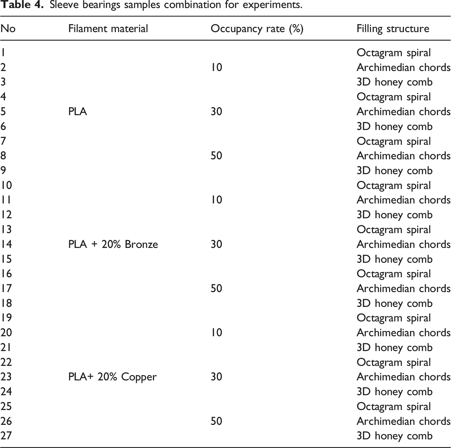
Additive Manufacturing (AM) method enables to produce products easily, cheaply and quickly with more complex geometry compared to traditional production methods. In this context; Fused Deposition Modeling (FDM) is a widely used for AM method that requires a large number of process parameters. In this study, it is aimed to experimentally investigate the damping capabilities of the metal/polymer composite sleeve bearings printed using FDM. A total of 54 pieces (27 pairs) were printed from composite filaments such as nine pairs for each of PLA, PLA + 20% Bronze, and PLA + 20% Copper metal/polymer with different filling structures (Octogram spiral, Archimedian chords, and 3D Honey comb) and different occupancy rates (10, 30, and 50%), respectively. The experiments were carried out using the shaft-bearing system under the same operating conditions at a rotational speed of 900 revolution per minute (rpm), and vibration data was collected from the rotating shaft with proxy probes. Rotating shaft position is very important to determine journal position in bearing for understanding deterioration in the bearing. Bode and Orbit plots are used to detect the level of deterioration in the bearing. The value of bearing to shaft clearence can vary widely depending on application. Since the bearings were heavily loaded, they were compressed by radial load caused large clearence. The results showed that compressed bearing had significant influence on the stability of rotating shaft system and significant differences in damping capabilities of composite sleeve bearings with different filling structures and occupancy rate. Increasing occupancy rate decreases the vibration amplitude values in copper-reinforced sleeve bearing but increases in bronze-reinforced sleeve bearing. From the microstructure analysis, it has been observed that the vibration absorbation capability is better due to the more homogeneous distribution of the copper reinforced bearings than the bronze reinforced bearings. Also, vibration absorption capability of sleeve bearings with 3D Honeycomb filling structure
Introduction
Additive Manufacturing (AM) is the construction of complex three-dimensional parts from Computer Aided Designed (CAD) model data by depositing successive layers of material. Metal, polymer, ceramic and composite materials can be used more easily and quickly to manufacture parts of complex geometries that often can not be manufactured by any other manufacturing methods.1–3 Fused Deposition Modeling (FDM) is used for AM method. The FDM provides suitable technology, low cost and using of many material types. 4 The most important advantages of this method that it is possible to produce without preliminary preparation and residual materials. Besides these, geometric restrictions of products are not problems comparing to traditional production methods.5–9 However, mechanical properties of produced products with FDM method are slightly lower strength than the one produced with traditional manufacturing methods. This situation limits the production of parts with FDM.10–16 However, it is possible to produce product with improved mechanical properties using metal/polymer composite filaments formed by adding additives such as copper and bronze into plastic materials. Copper and bronze reinforcement can increase the strength of the products using filament materials made of Acrylonitrile Butadiene Styrene (ABS), Polylactic Acid (PLA), Polyamide (PA), Polycarbonate (PC) and various mixtures of these materials. 16
Since the products with metal/polymer composite filaments have good strength and low intrinsic mass properties, their use in industry is increasing rapidly, and they become even more important with their low cost and comparable mechanical properties. 17 Products produced from composite material using the FDM method are widely used in aerospace and aircraft, automotive, and marine industry due to their lightness, rigidity, high strenght, good wear and heat resistance. To improve the mechanical properties and to increase performance of the product with FDM, researchers18–20 have developed metal/composite materials that can be used with existing FDM. Besides the mechanical properties of polymer composite materials, vibration damping capability of materials, has great importance that affects system performance and stability. In recent years, there are a large number of studies21–38 that have been made considering of non metal composites products using 3D printing.
However, a limited number of studies have been conducted in the literature on vibration damping capability of products made from composite materials using FDM method. Reader can refer to 39 and a literature review 40 for the studies.
This study, experimentally investigates vibration damping capabilities of 3D printed metal/polymer composite sleeve bearings supporting a shaft made of turned, ground, and polished steel.
Material and method
Composite sleeve bearing samples models were first designed in computer environment and transferred to the slicing interface program Slic3r for FDM. After the processing coordinates were created in the program, they were sent to the 3D printer via a USB connection and printed on the printer’s platform. In Figure 1, technical drawing of the sleeve bearing with dimensions (mm) is given. Technical drawing of the sleeve bearing.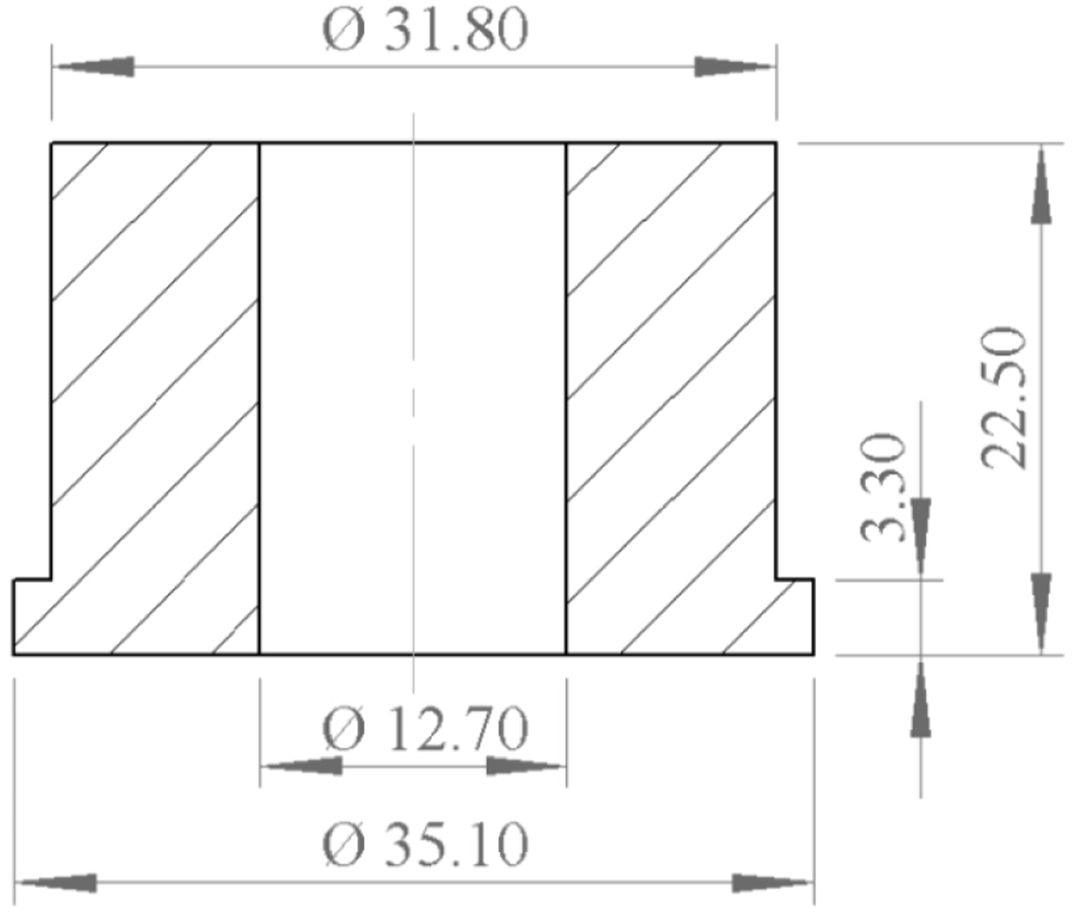
A total of 27 pairs of sleeve bearings are Printing process of composite sleeve bearings by FDM; a) PLA b) PLA+%20 Bronze c) PLA+%20 Copper.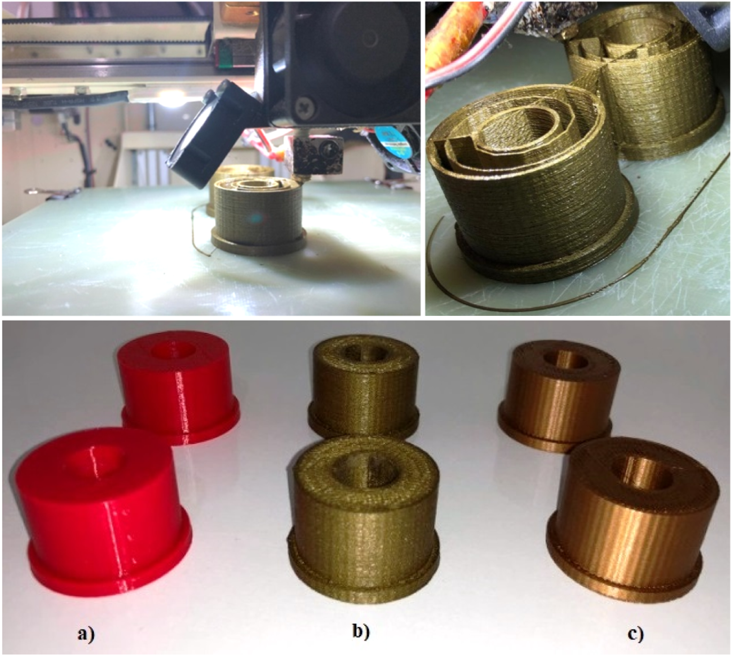
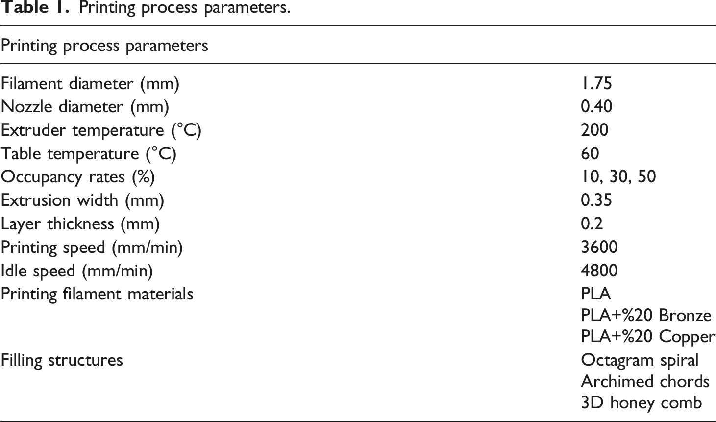
Printing process parameters.
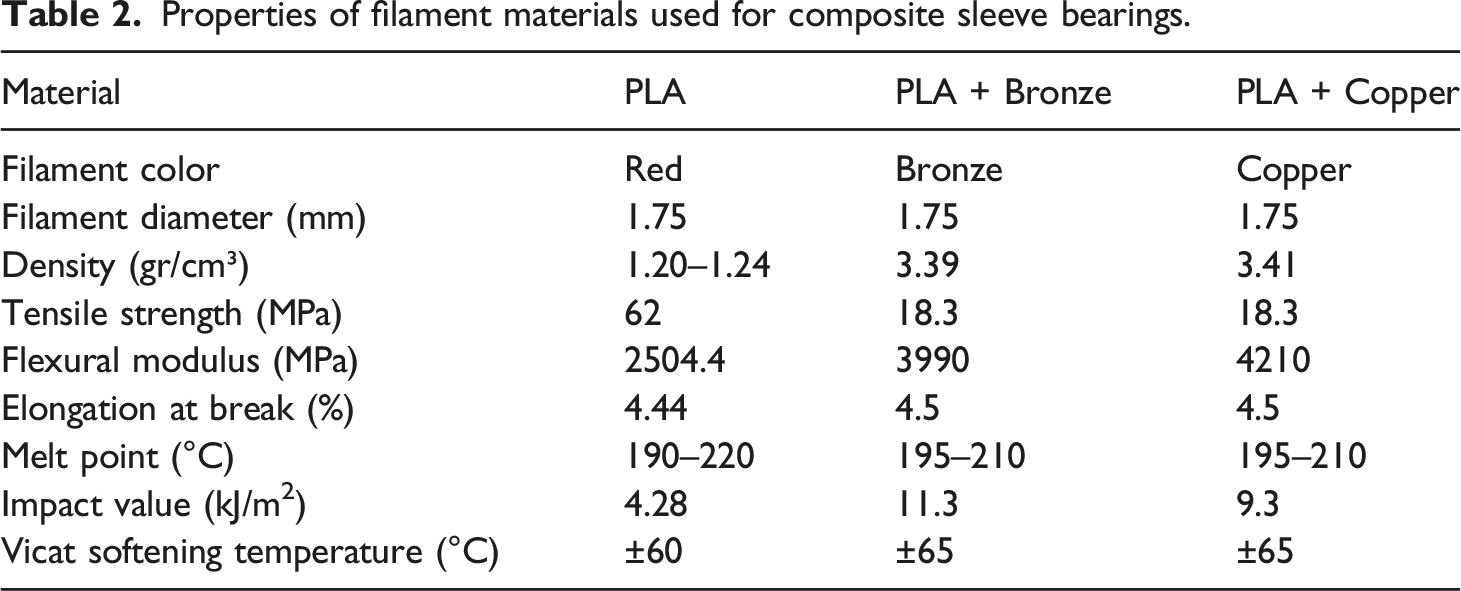
Properties of filament materials used for composite sleeve bearings.
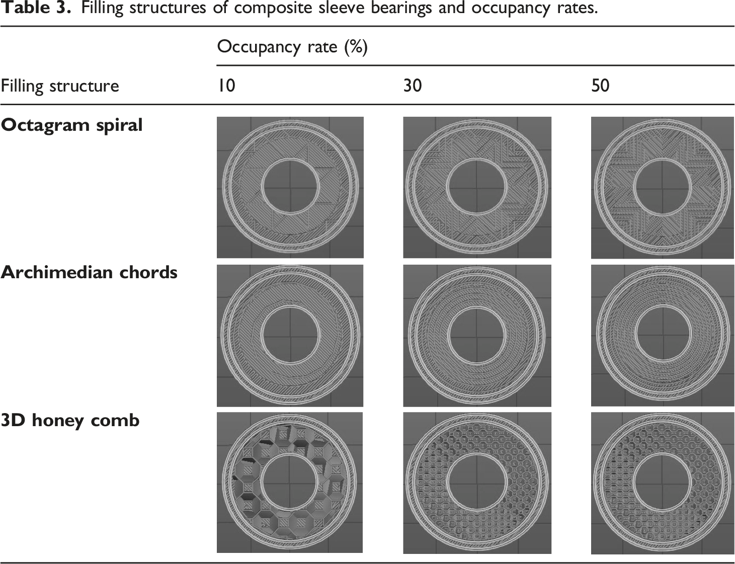
Filling structures of composite sleeve bearings and occupancy rates.
Sleeve bearings samples combination for experiments.
Experimental setup used in this study is shematically shown in Figure 3. The shaft system is supported by two composite sleeve bearings fitted into the solid housings. The length and diameter of the shaft present in the test rig is 130 mm and 12.70 mm, respectively. The radial load (1505 gr) is provided by a disk mounted on the shaft unsymmetrically. The shaft and a 0.5 HP motor are connected with flexible coupling to decrease vibration generated by the motor. The speed controller allowed the system to operate in the range of 0 to 3000 rpm. In order to measure and plot the shaft orbit relative to the bearings, two eddy currents proxy probes are mounted close the disk in the horizontal and vertical directions, respectively. SpectraQuestTM software and hardware equipped with a low-pass anti aliasing filter are used for data acquisition. Experimental setup; (1) Rubber isolators; (2) 0.5 HP Motor; (3) Base; (4) Flexible coupling; (5) Sleeve bearing; (6) Sleeve bearing housing; (7) Shaft; (8) Rigid support for proxy probe; (9) Disk (1505 gr); (10) Proxy probe (Ch 1); (11) Proxy probe (Ch 2); (12) Variable speed controller; (13) Tachometer.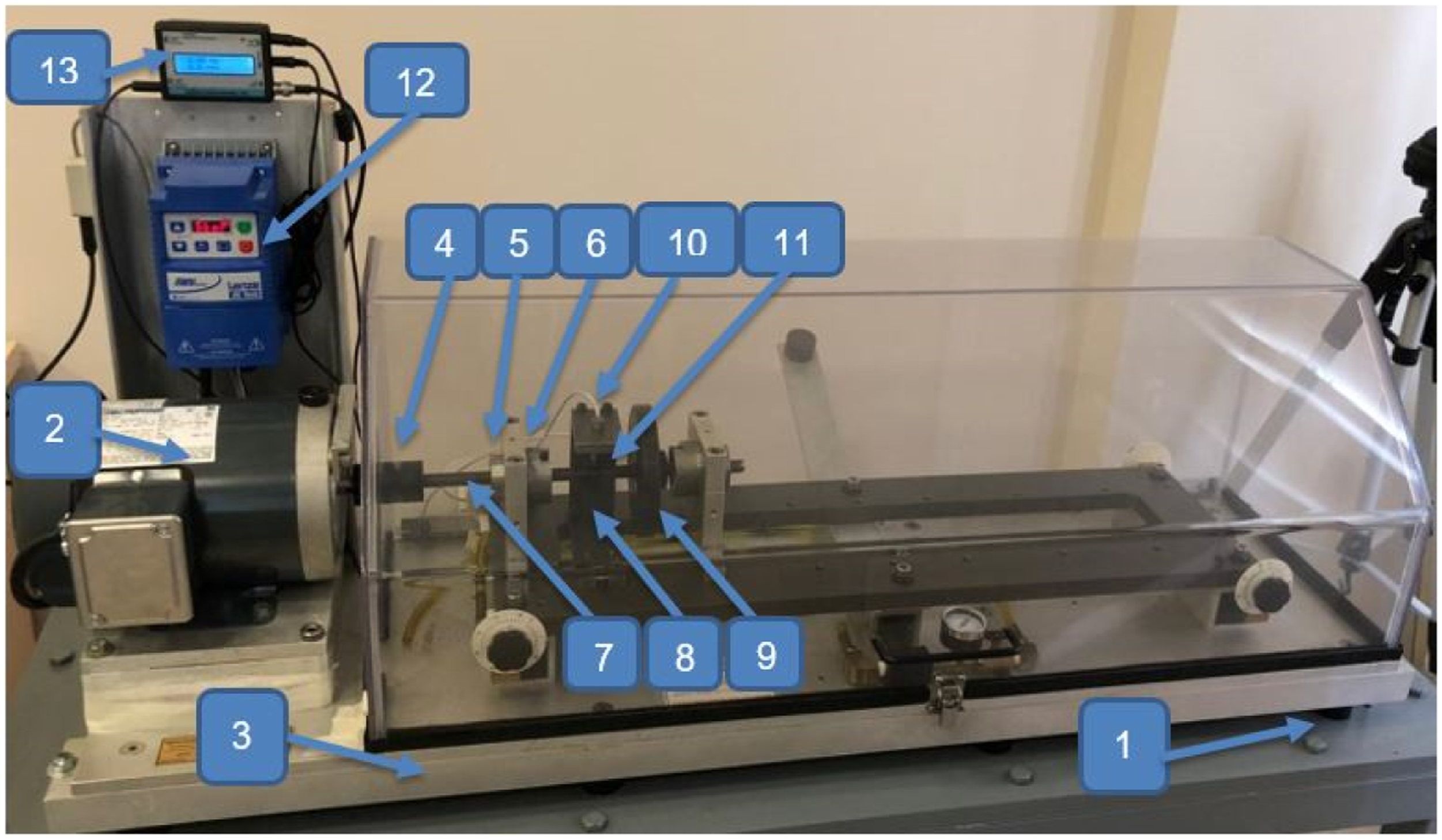
Findings and discussion
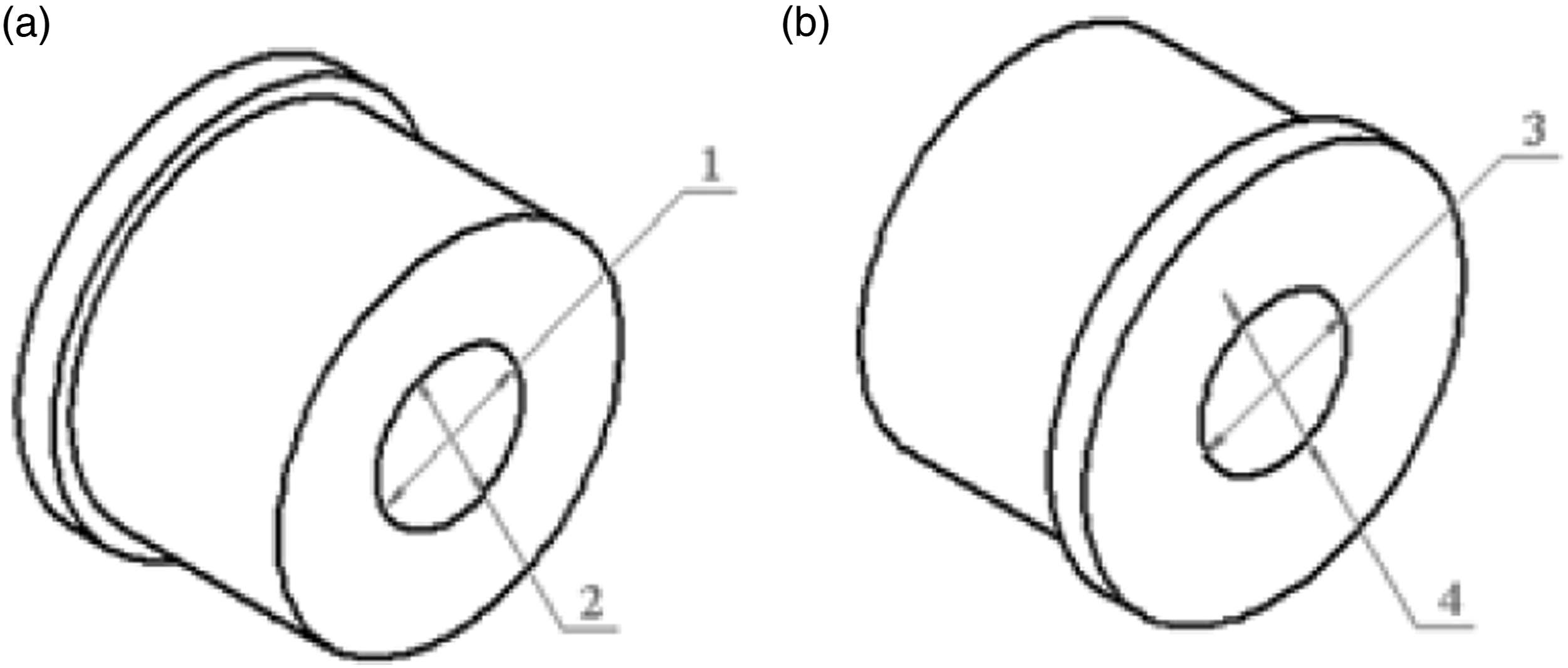
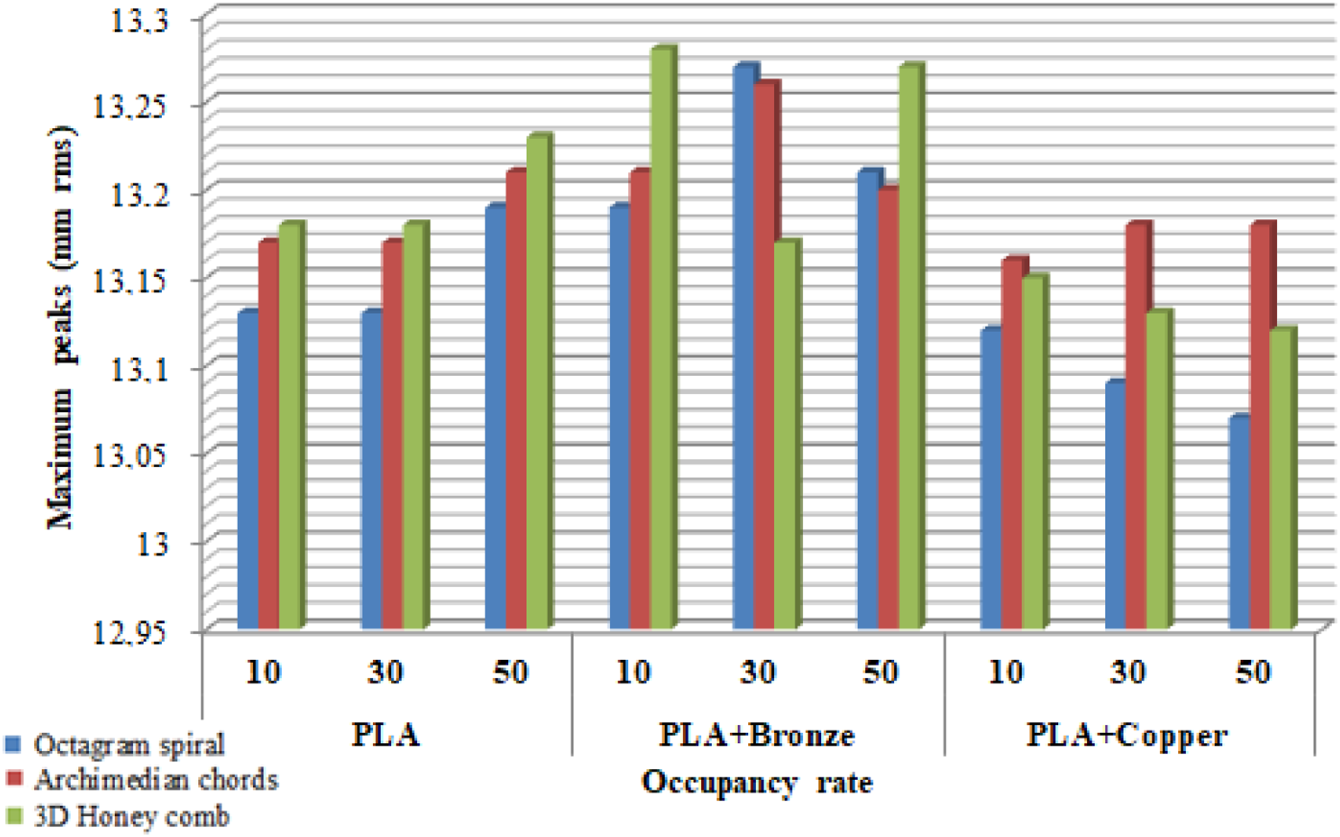
Rotating shaft posititon is very important to determine journal position in bearing for understanding deterioration in the bearing. Bode and Orbit plots shown in Figure 4 and Figure 5 are used to detect the level of deterioration in the bearing. The maximum amplitude values obtained from bode plots are presented in Figure 6. The vibration displacement in the vertical (Ch1) and horizontal (Ch2) directions are combined together to obtain the actual rotating shaft displacement relative to bearing vibration that gives orbit plots. As seen in Figure 5, the orbit plots displayed totaly different orbital shapes which indicates that the dynamic characteristics of the rotating shaft supported by composite sleeve bearings with different filling structures and occupancy rate. It can be seen from the plots that the radial load provided by disk caused increase in magnitude in vertical direction and orbit became ellipsed. Thus, the radial load caused the orbits to have lower amplitude in horizontal direction compare to vertical direction and made the ellipse look thinner. In order to see radial load effects on internal diameter change, all bearings internal diameter were measured from four different locations shown in Figure 7. The mesured internal diameter values are given in Table 5. The average values of the bearings internal diameters given in Figure 8 are within acceptable tolerance range. The value of bearing to shaft clearence can vary widely depending on application. Since the bearings were heavily loaded, they were compressed by radial load caused large clearence. The results showed that compressed bearing had significant influence on the stability of rotating shaft system. Thus loose running fit had largest vibration amplitude value in the rotating shaft system. Bode plots. Orbit plots. Maximum vibration peaks values (Ch1). Diameter measurement locations after experiments. Internal diameter measurement values of sleeve bearings after experiment (mm). Average internal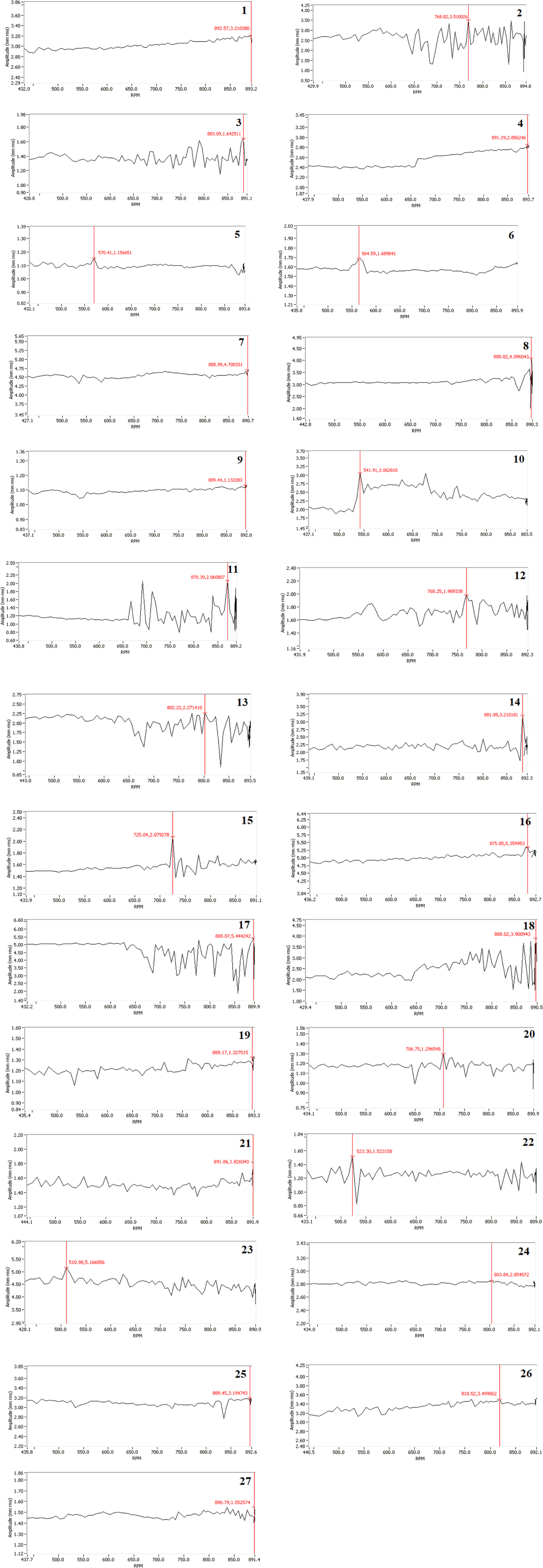
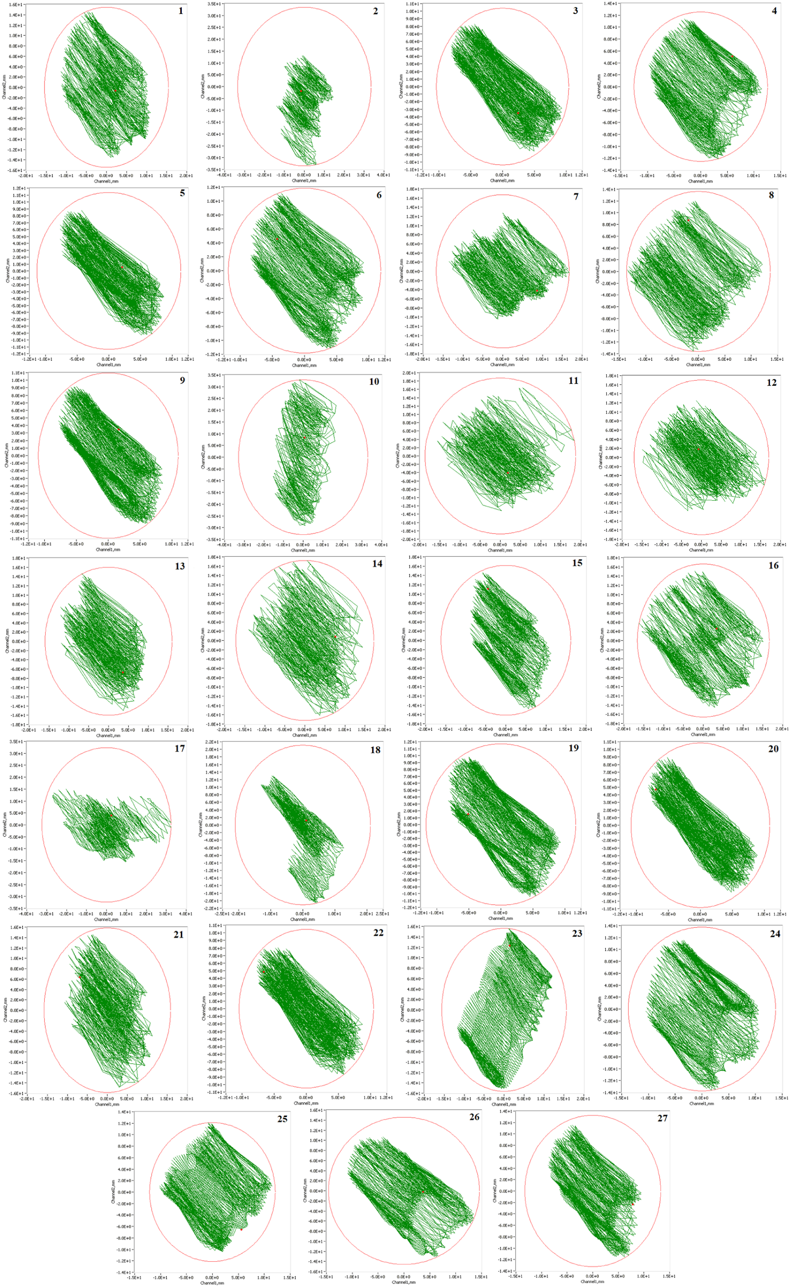
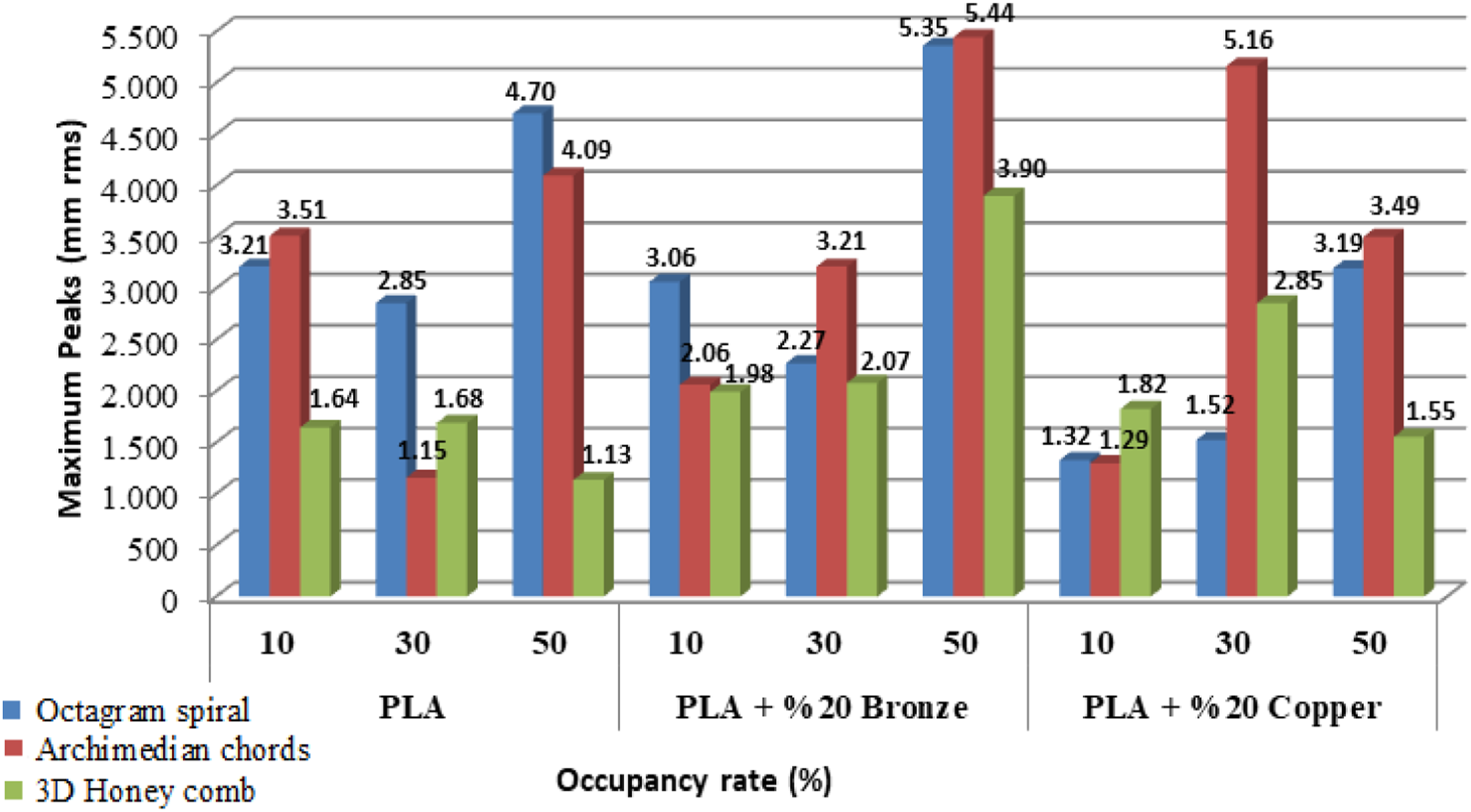

In order to see damping capabilities of 3D printed metal/polymer composite sleeve bearings in the rotating shaft system, the sleeve bearing were printed using Octogran spiral, Archimedian chords, and 3D honey comb filling structures. For each structure, the occupancy rates of 10, 30, and 50% were utilized using PLA, PLA+20% Copper, and PLA+20%20 Bronze filaments, respectively. Since the gravity direction is more crucial, the data collected from vertical direction channel (Ch1) is presented. It can be seen from the maximum vibration amplitude peaks values in Figure 6 obtained from bode plots in vertical direction that the sleeve bearing having filling structure of Archimedian chords with 50% occupancy rate using PLA+20% Bronze filament has the highest vibration amplitude value while the sleeve bearing having filling structure of 3D honey comb with 50% occupancy rate using PLA has the lowest vibration amplitude value. So, it can not be ruled out that occupancy rate
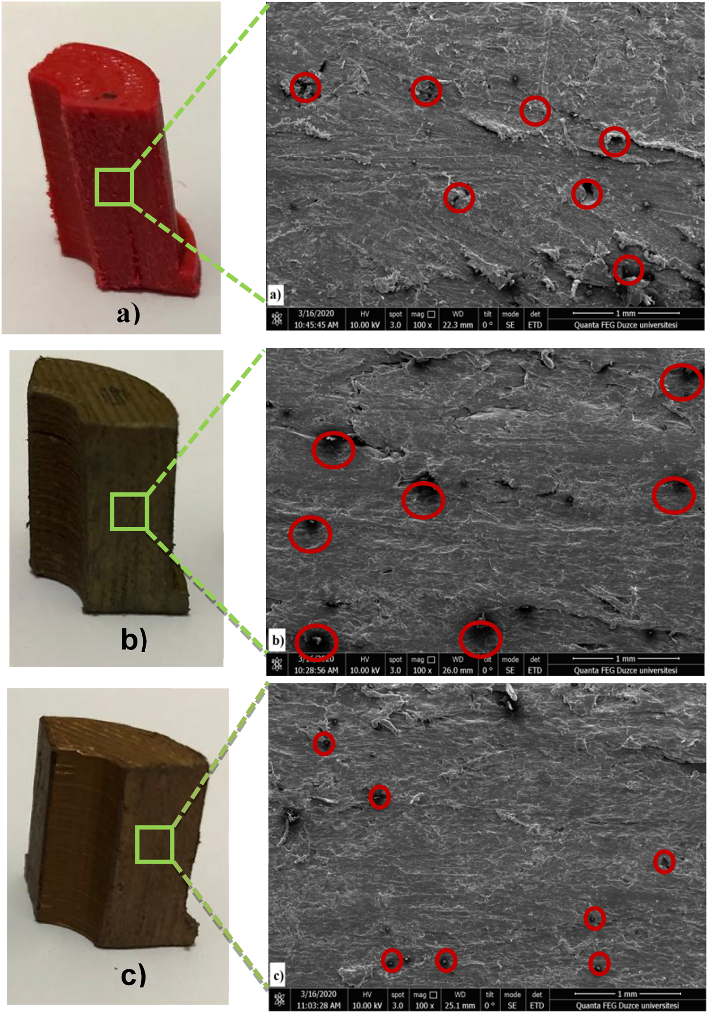
A microstructural analysis was performed on PLA, PLA + 20% Bronze, and PLA + 20% Copper filament materials and printed sleeve bearings structure using Scanning Electron Microscope (SEM) to examine microstructural effect on damping capacity. The micro level observations of filament internal structural given in Figure 9 and of the sleeve bearings structure in Figure 10 showed voids formation. It can be seen in Figure 10 that voids were leaved while FDM printer was printing the sleeve bearings as layers which were not uniformly bound. From Figure 9 and Figure 10, larger and more voids were recognized in PLA+20% Bronze compared to the standard PLA and PLA+20% Copper filaments and the sleeve bearings. The larger voids caused higher vibration amplitude behavior. The sleeve bearings with the standard printed with PLA filament have SEM micrographs for sleeve bearings structures; a) PLA filament inner structure, b) PLA + 20% Bronze filament inner structure, c) PLA + 20% Copper filament inner structure. Surfaces section of metal/polymer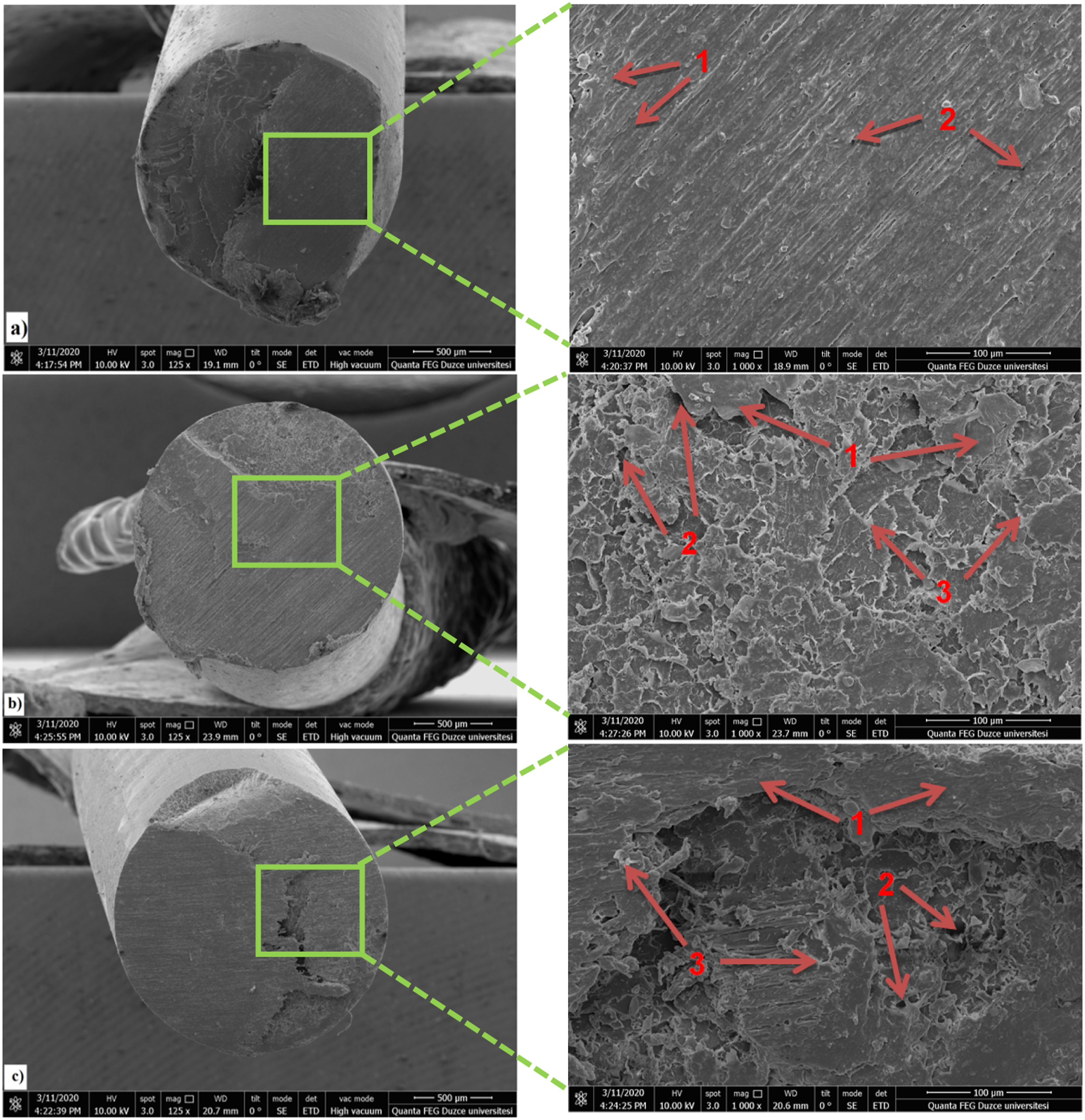
Conclusion
The present study was experimentally to investigate the damping capabilities of the metal/polymer composite sleeve bearing printed using FDM which is widely used for AM. Damping capacity is ability of a material to absorb vibrational energy and it is a desirable property in many application in rotating shaft system. The results of the investigation showed that there are significant differences in damping capabilities of composite sleeve bearings with different structures and occupancy rate. The most obvious finding to emerge from investigation is that increasing occupancy rate decreases the vibration amplitude values in copper - reinforced sleeve bearings. Taken microstucture analysis together, it can be concluded that the vibration absorbation capability is better due to the more homogeneous distribution of the copper - reinforced bearings than the bronze-reinforced bearings. In general, therefore, it seems that sleeve bearings with 3D honey comb filling structure vibration absorbation capability increase significantly proportion to the occupancy rate. Standard PLA has superior damping capacity when compared to Bronze and Copper reinforced PLA. It can be stated that the damping capacity of sleeve bearings appears to depend not only on the printing parameters but on the nature of the material used.
Footnotes
Declaration of conflicting interests
The author(s) declared no potential conflicts of interest with respect to the research, authorship, and/or publication of this article.
Funding
The author(s) disclosed receipt of the following financial support for the research, authorship, and/or publication of this article: This study was supported by Düzce University Scientific Research Projects Coordinator (Project No: BAP - 2018.22.01.773).