
Abstract
Numerical parametric study is performed to investigate ballistic impact performance of a novel fiber metal laminate (FML) based on ultra-high molecular weight polyethylene (UHMWPE) fiber composite and aluminum 2024-T3 layers. A finite element modeling is developed and validated with experimental tests. A user-defined material subroutine based on continuum damage mechanics is used to define damage constitutive model of UHMWPE composite. High velocity impact simulations shows similar modes of failure to that observed in experiments. The effect of various parameters such as metal thickness, composite core thickness, metal volume fraction (MVF), and lay-up sequence on ballistic limit velocity, absorbed energy and specific perforation energy (SPE) of samples has been investigated. The results show that increasing the number of composite layers increases the SPE while increasing the thickness of metal layers decreases the SPE. Although, as the core thickness increases, the growth of SPE decreases. Changes in the lay-up sequence do not have much effect on ballistic velocity and absorbed energy. Whereas, the MVF is an important parameter in the high velocity impact performance of the PERALL specimens. In addition, with equal MVF, stacking sequence change has no significant effect on the ballistic limit velocity. Finally, a simple linear equation is suggested to describe the relationship between MVF and specific perforation energy.
Keywords
Introduction
The hybridization of thin sheets of metal and fiber-reinforced composite laminates is known as FMLs, which with theirs combined properties, have many applications in various industries. 1 The most common FMLs are glass-reinforced aluminum laminates (GLARE), aramid reinforced aluminum laminate (ARALL), and carbon reinforced aluminum laminate (CARAL). Combining valuable properties of metals such as ductility and good impact resistance with the advantages of fiber-reinforced composites such as light weight, high strength and fatigue resistance, FMLs are a suitable choice for use in air vehicles.2,3 Investigating the impact behavior of FMLs as one of their advantages has always been of interest to researchers. Also, due to their advantages and applications, the production of new FMLs has recently been considered. For example, the fabrication of FMLs using basalt fiber, 4 self-reinforced polypropylene fiber, 5 with 3D printed glass fiber composite, 6 and carbon fibers with different aluminum alloys 7 are a part of recent works in this field.
Various fibers have been used in composite cores of FMLs. UHMWPE fiber is a fiber with unique properties such as low density and high strength; and its combination with thermoplastic polymer matrices makes a composite with low weight, and high strength and impact resistance.8,9 The unique properties of UHMWPE composite have led to it being used as a component in hybrid structures in recent research. Some researchers have studied the ballistic behavior of hybrid composites made from UHMWPE fibers and other fibers such as carbon 10 and basalt. 11 Li et al. 12 fabricated FML with titanium metal layers and UHMWPE composite laminate as a core, and performed high velocity impact tests on the samples. Their observations showed that FMLs with UHMWPE fibers performed better than FMLs with carbon fibers and titanium face sheets. Recently, Mansoori et al. 13 introduced a FML based on UHMWPE fibers and aluminum layers and experimentally investigated its behavior under ballistic impact. Results showed that the new FML has a good performance against high velocity impact compared to GLARE specimen.
High velocity impact failures is the main form of damage in aerospace structures. Conical projectile is used as a common type of impactor in high velocity impact tests for a variety of composite and FML materials. Zhu et al. 14 experimentally investigated a UHMWPE composite plate under high velocity impact with conical projectile. Their observations showed that the fiber failure and lateral displacement of fibers occurred at impact zone. Zarei et al. 15 investigated the ballistic behavior of GLARE impacted with conical and flat projectiles. Results show that the ballistic limit of GLARE with conical projectile is less than flat projectile and there is no plug in targets impacted with conical projectile. Xu et al. 16 experimentally investigated CARAL specimens under high velocity impact with conical, hemispherical, and flat projectile. The lowest ballistic limit was observed for specimens impacted with conical projectile compared with hemispherical and flat projectile.
Ballistic and high velocity impact experiments are expensive and time-consuming. Finite element method (FEM) has been widely used because of its less limitation and capability for modeling the damage mechanisms and penetration process during impact period. One of the most important parts of numerical simulation of FMLs is the simulation of the composite core. Haque et al.17,18 introduced a model for UHMWPE composite laminates with a shell model that provides deformation mechanisms similar to the experiment. Lässig et al. 19 proposed a non-linear orthotropic hydro-code model and simulated the hypervelocity impact on UHMWPE composite. The results provided good predictions of the residual velocity. This model was developed by Nguyen et al. 20 considering a sub-laminate to better predict the ballistic limit and back-face deflection (BFD). Sub-laminates were considered as an orthotropic material with orthotropic elastic–plastic strength, failure criteria and directional hardening; and connected by tied contacts in ANSYS Autodyn software. Hazzard et al. 21 recently modeled UHMWPE composite laminate with a similar sub-laminate approach for a range of loading conditions in LS-DYNA software. MAT162 (material model) was used for modeling the sub-laminates as fabric composite. The literature review shows that no numerical study has been performed to simulate the ballistic behavior of UHMWPE composites impacted with conical projectile.
During the impact process, several failure modes occur, such as fiber/matrix tension, fiber/matrix compression, fiber shear punch, fiber crush, and matrix shear. Therefore, for numerical simulations, it is essential to choose a model that correctly considers the modes of damage. Continuum damage mechanics (CDM) with considering different damage modes and introducing damage variables is an effective approach for impact modeling. The CDM predict damage initiation using failure criteria, and then stiffness is degraded with different methods until complete failure. The ABAQUS/Explicit is capable of modeling composite laminate under impact load. Many researchers have modeled the low velocity22–24 and the high velocity impact25,26 in ABAQUS software by writing subroutines based on Hashin’s criterion 27 and CDM. Delamination or inter-laminar damage is an important damage mode under impact loading for laminated composites. There are two methods for modeling the delamination during impact loading based on Cohesive Zone Model (CZM): (1) using cohesive elements and (2) applying surface-based cohesive contact model. Both methods have been used in previous researches for simulation the delamination in ABAQUS software under low and high velocity impact.28–32
Due to the mentioned properties of UHMWPE, this composite can be a good candidate for hybridization with aluminum alloys and making a light weight FML with special properties for aerospace applications. The main purpose of this paper is to numerically investigate the effect of different geometric parameters as well as the type of aluminum alloy on ballistic behavior of polyethylene reinforced aluminum laminate (PERALL) specimens. Progressive damage modeling includes the 3D strain-based model for fabric composite with fiber failure modes such as compressive, tensile, punch shear and crush; and matrix failure modes such as in-plane shear and through thickness delamination. Inter-laminar damage is simulated utilizing the CZM method based on cohesive contact model between composite layers as well as composite and metal interfaces. The ballistic impact with a conical projectile is simulated, and modes of failure and residual velocity against conical projectile are verified using experimental results. The effect of various parameters on the ballistic limit velocity, absorbed energy, and specific perforation energy (SPE) of the samples is investigated.
Numerical simulation
Finite element modeling
Finite element (FE) model is established based on ABAQUS/Explicit to analyze the behavior of FML specimens under impact loading with conical projectile. For modeling the UHMWPE laminate, a cross-ply sub-laminate homogenization approach has been used. Each Schematic of FMLs (a) 2/1 lay-up sequence configuration, (b) 3/2 lay-up sequence configuration.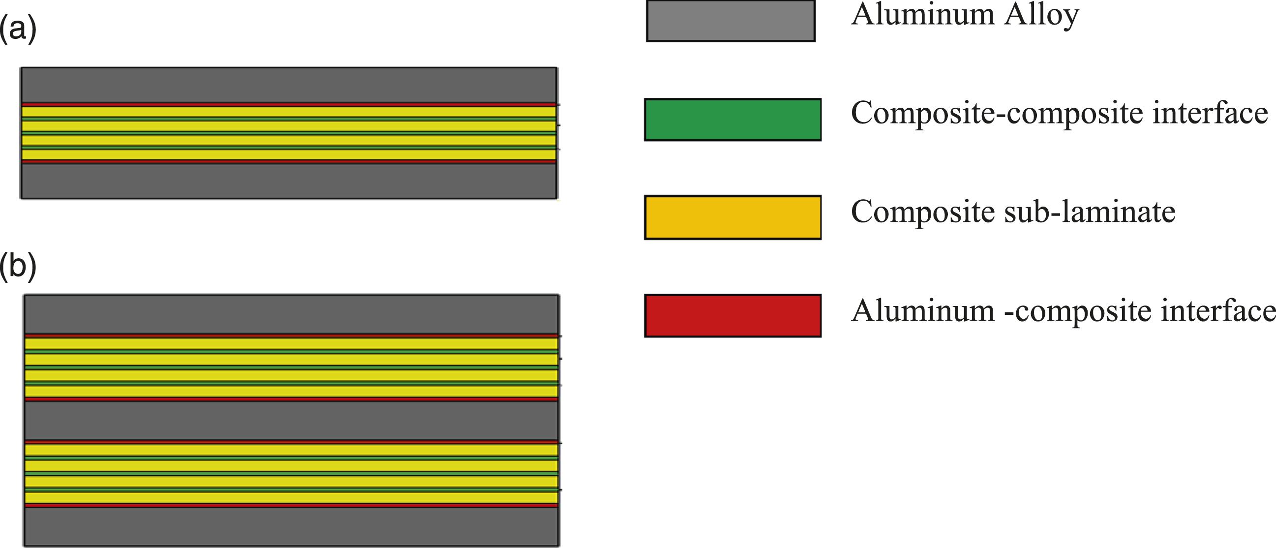
Deformation and damage mainly take place in the contact area and around it in high velocity impact simulation. Therefore, the biased mesh with increasing element size approaching the edge of the layer are used. A mesh study with different element numbers was conducted and a mesh independency was observed at number of 100 elements across edge with an aspect ratio of five for each layer. Aluminum layers, composite sub-laminates, and projectile are created using hourglass controlled eight-node 3D reduced elements (C3D8R). also Two clamps are established in the model as a rigid body for boundary condition and meshed with C3D8R elements, considering the material properties as: ρ = 7800 kg/m3, E = 210 GPa, and υ = 0.33. The FE model of FML under impact loading with conical projectile is displayed in Figure 2. For the bottom clamp, all nodes are fixed and for the top clamp, the nodes along 1 and 2-directions are fixed. A pressure of 2 MPa is applied to the front surface of top clamp to simulate the clamping pressure imposed in the experiments. Finite element model of FML under high velocity impact with conical projectile.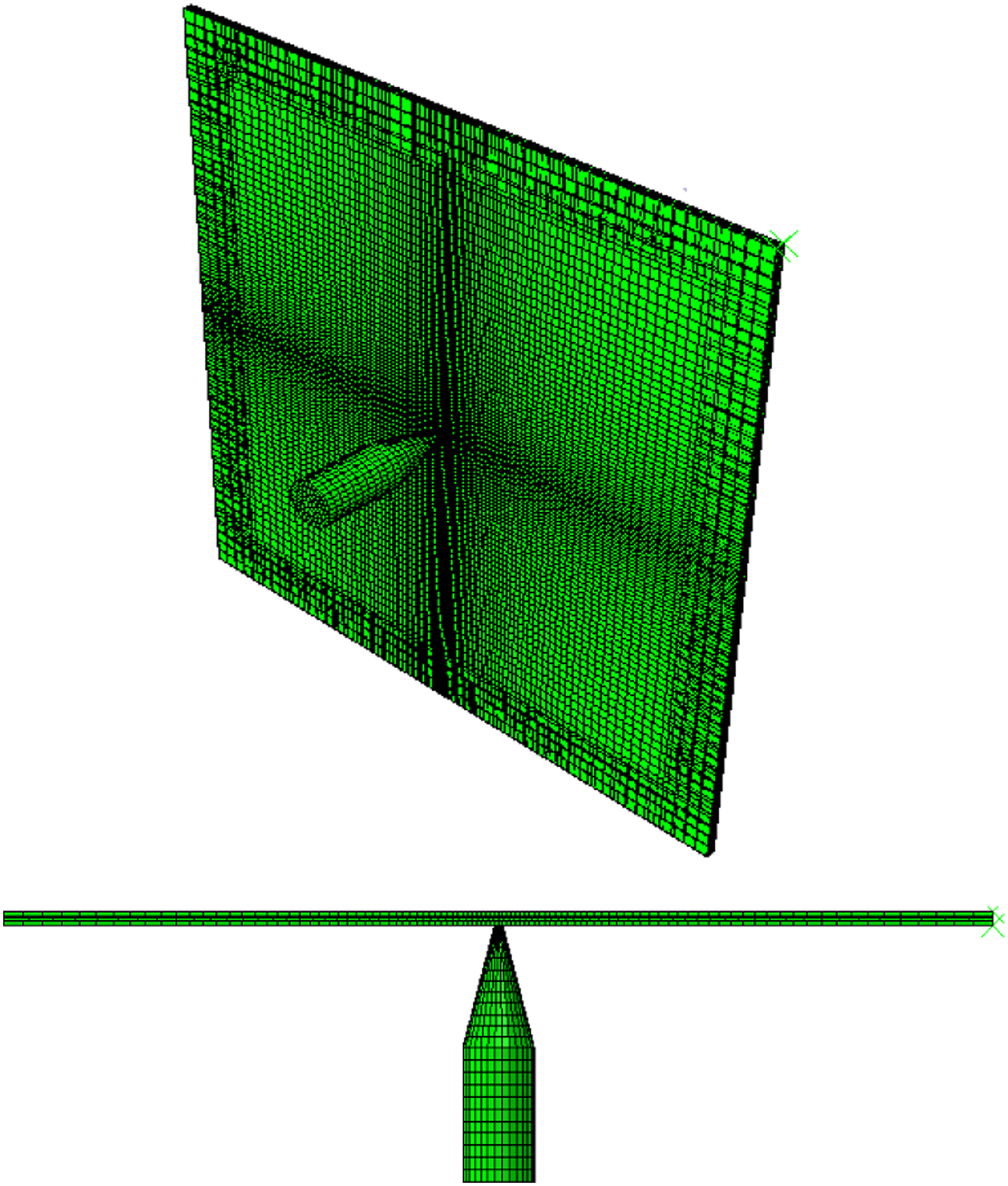
Damage model of metals
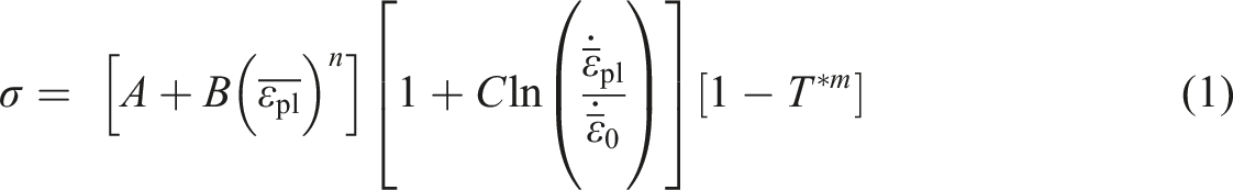
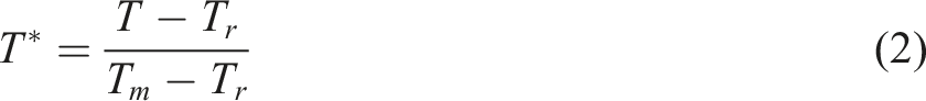
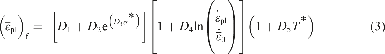
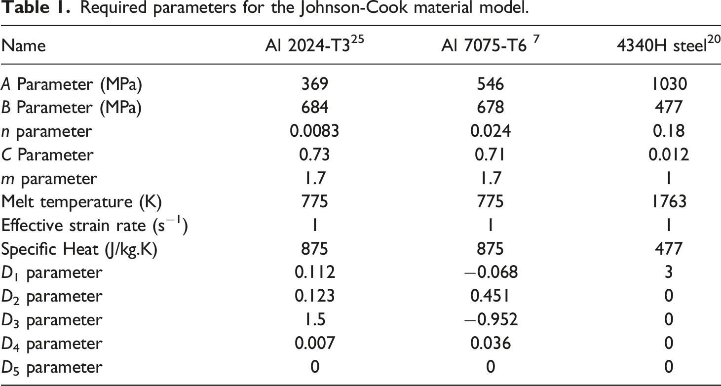
For simulation metals in the impact and rate-dependent problems, Johnson–Cook model
33
embedded in ABAQUS is commonly used. Johnson–Cook model is an empirically based model with material parameters including A, B, C, m, and n as follows
34
Required parameters for the Johnson-Cook material model.
Damage model of UHMWPE composite
Failure criteria for composite sub-laminates.
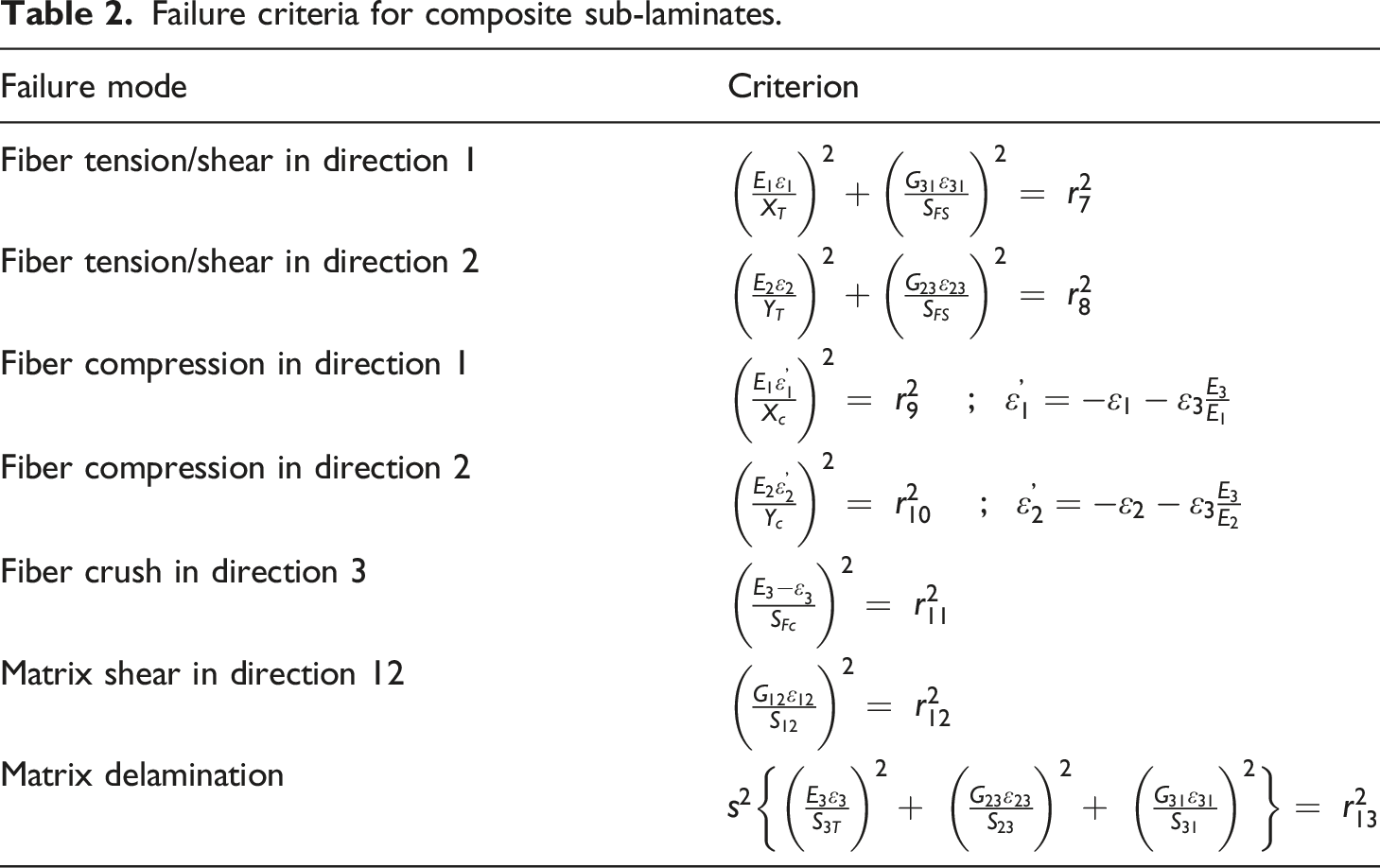
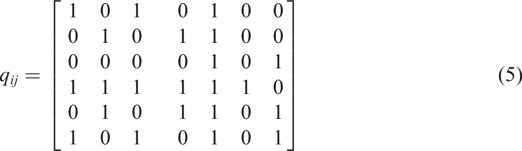
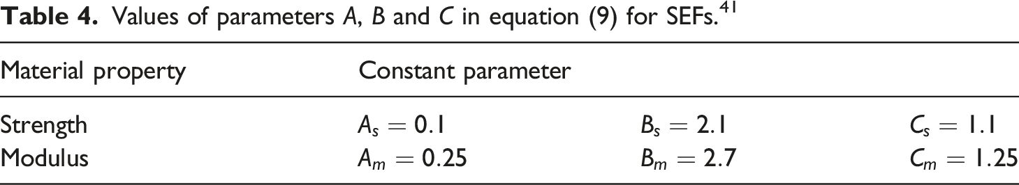
After obtaining the values of r, the effect of these values on the tensile and shear modulus must be examined. For this purpose, the matrix q is used that determines the effect of the failure on the modulus. This matrix has seven columns and six rows, in which each column represents a damage mode threshold value (r7–13), and each row represents one of the loading directions (damage variable). The q matrix for fabric is
35
According to Matzenmiller et al. ,
37
the growth rate of damage variables is defined by the exponential evolution law. It was shown that the exponential evolution damage model is more accurate compared to experimental observations than the linear evolution damage model
38
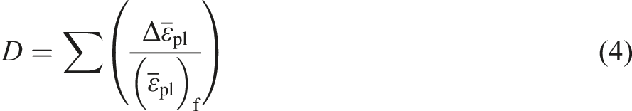
The damage function (1) Fiber damage in the direction one (2) Fiber damage in the direction two (3) Fiber crush damage (4) Matrix and delamination fd8damage 

After calculating the values of 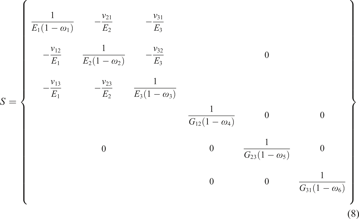
This matrix is used to calculate the strain in orthotropic materials. Having the matrix S, the stiffness matrix C is obtained and the stresses are calculated as
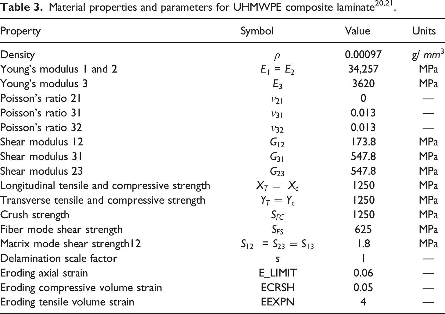
The material model and failure criteria are implemented with a user-defined subroutine (VUMAT) in ABAQUS/Explicit. The local stiffness reduction in the material due to internal damage can lead to element distortion and divergence during problem solving. To remove the damaged elements, the maximum strain criterion is implemented in the VUMAT subroutine based on the strain value exceeding the specified values in two directions one and two. This maximum value is presented in Table 3 as E_LIMIT. In addition, the volume strain criterion is utilized such that when tensile relative volume strain (ratio of current volume to initial volume) is greater than a specified limit, the element is eliminated. Also, when compressive relative volume strain is smaller than a specified limit, the corresponding element is eliminated. The specified values are marked with EEXPN and ECRSH in Table 3, respectively.
Effect of strain rate
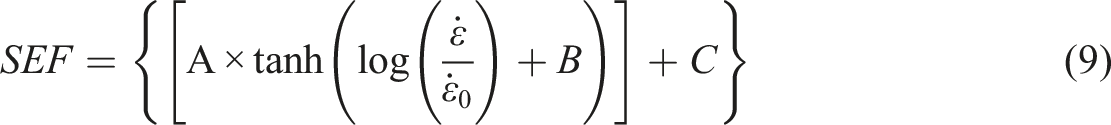
The tensile properties of UHMWPE composite are highly dependent on strain rate.39,40 Hence, in this study, the effect of strain rate on the modulus as well as the strength of UHMWPE composite was considered. Russell et al.
39
proposed a method for testing the tensile response of UHMWPE composite for the strain rates between

Damage model of the interface
Delamination is a common mode of damage between composite layers as well as between metal-composite interfaces in FMLs. ABAQUS software uses a traction-separation law in the CZM technique for simulating the delamination. Two failure criteria are required for interface damage modeling (including damage initiation and final damage). For damage initiation, a quadratic nominal stress criterion can be used as follows
42


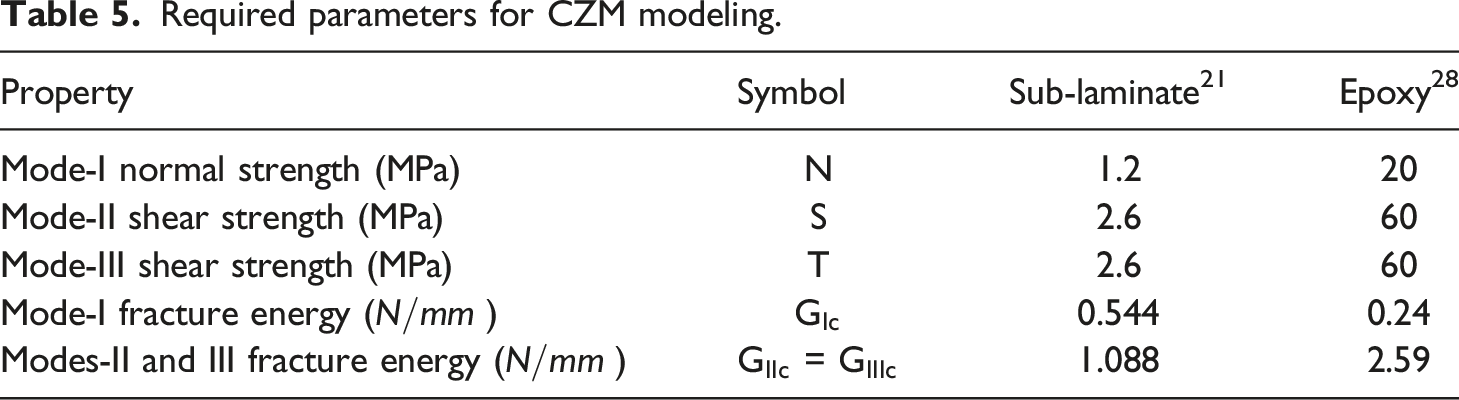
Required parameters for CZM modeling.
Results and discussion
Verification with experimental results
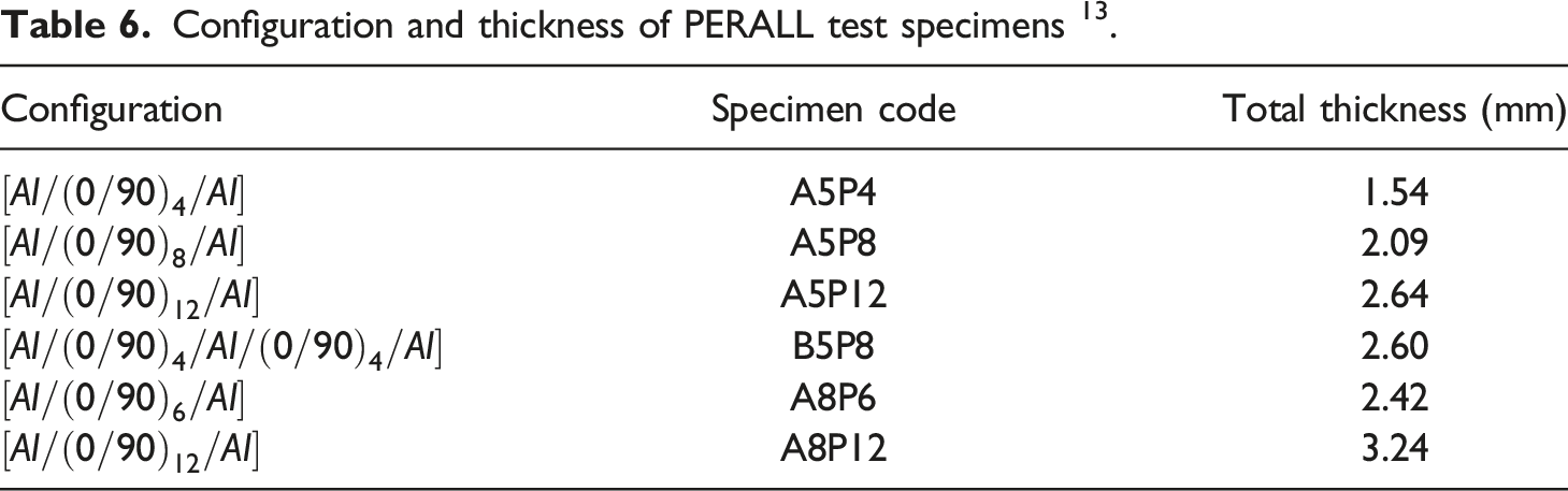
Configuration and thickness of PERALL test specimens 13 .
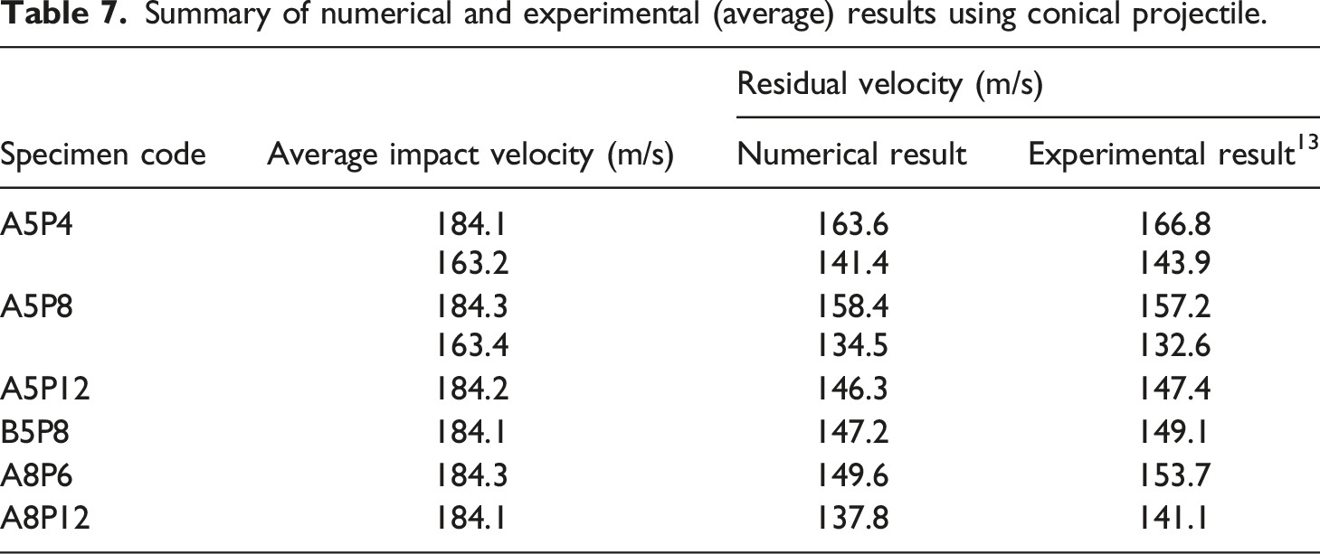
Summary of numerical and experimental (average) results using conical projectile.
Failure mechanisms
The samples were exposed to conical projectiles at two velocities of about 163 m/s and 184 m/s. In all specimens, the projectile penetrated the target completely and a hole about the size of the projectile was created in the target. The results for the damage pattern show a good correlation between experimental observations and numerical simulation. In all targets, the front and back metal layers failed through plugging and petalling, respectively (as in Figure 3). Perforated damage surface of the specimen A5P4 subjected to impact with conical projectile: (a) front metal layer, (b) back metal layer.
Figure 4 illustrates the damage mode observed in cross sectional images for three samples obtained from numerical analysis and experiments. It can be seen that no significant deformation occurs in the aluminum layers except in the perforated area. A circular hole in the composite core has been generated by the projectile during perforation. Delamination is observed in UHMWPE composite core as well as interfacial debonding of metal and adjacent composite layers around the impact point. As shown in Figure 4, around the impact point, the composite core is deformed to fit the aluminum layer. Because at the same time as the tip of the projectile penetrates the target and the conical part of the projectile progresses, the fibers are pushed aside by the projectile. This mechanism in the composite core, after the removal of the aluminum layers, is shown in Figure 5(a). Due to the low inter-laminar shear strength of the UHMWPE composite laminate, delamination occurs around the impact point. In addition, the low content of polyurethane matrix in the pre-preg material and the ductile behavior of UHMWPE fibers cause the fibers to deform easily at the impact point. As shown in Figure 5(b), numerical simulation well predicts this mechanism. It should be noted that this mechanism is not seen in FMLs with brittle behavior of fibers, such as carbon reinforced aluminum laminate, exposed to conical projectile .
16
Damage morphologies and numerical predictions of samples subjected to impact test with conical projectile impacted at 184 m/s. (a) Specimen A5P4, (b) specimen A5P12, (c) specimen B5P8. Damage morphologies for the composite core of specimen A5P12 subjected to impact with conical projectile (a) experimental observation, (b) numerical simulation.
Figure 6 illustrates the penetration process (Figures 6(a)–(h)) and its associated contact force history (Figure 6(i)) for the specimen A5P12 under the impact. Penetration begins with a slight deformation and an increase in the contact force. By penetrating the projectile in the first layer of aluminum, the contact force decreases (Figure 6(a)) and then again by penetrating the projectile into the composite layers, the contact force increases until it reaches its maximum value (Figure 6(b)). The contact force drops sharply as the projectile tip penetrates the rear aluminum layer (Figure 6(c)). After that, the penetration continues to the end of the conical part of the projectile with the deformation of the core and the aluminum sheet and the contact force increases simultaneously until the deformation reaches its maximum value (Figure 6(d)). This deformation occurs elastically and with the gradual removal of the cylindrical part of the projectile, the deformation decreases and the contact force decreases with the penetration of the cylindrical section. At this point, the contact force is almost constant until the projectile penetrates completely (Figures 6(e) to (g)). Finally, the projectile completely loses contact with the target and the contact force becomes zero. The sample appears without bending deformation and only with damage in impact zone (Figure 6(h)). The simulated perforation process (a–h) and contact force history (i) for specimen A5P12.
Parametric study
In this section, the effect of different geometric parameters including composite core thickness, aluminum layer thickness, and lay-up sequence as well as the type of aluminum alloy on the impact behavior of PERALL specimens is investigated.
Effect of composite core thickness
To understand the effect of composite core thickness, ballistic limit velocity for PERALL specimens with four different core thicknesses was estimated and compared. Ballistic limit velocity is the maximum impact velocity that the projectile does not pass through the target. Targets were impacted with different impact velocities and complete penetrations against conical projectiles. At least three impact velocities with residual velocities were simulated to estimate the ballistic limit velocity using the Lambert–Jonas approximation
43
Numerical prediction of residual velocity with Lambert-Jonas 
Figure 8(a) shows the contact force history versus contact time for three specimens with different composite core thicknesses. The diagram consists of three parts. The first part is related to increasing the contact force until the projectile tip penetrates into the target and decreases the contact force. In the second part, the contact force increases again as the conical section progresses until the contact force decreases again with the penetration of the cylindrical section. In the third stage, it continues with an almost constant amount until the projectile penetrates completely. As seen in the Figure 8(a), with increasing core thickness, the force and contact time in the first and second parts increase sharply, especially in the first part, which involves the penetration of the projectile tip. In the first part, the contact force and contact time of specimen A5P12 is about two times that of specimen A5P4. This indicates an increase in the resistance to penetration of the targets by increasing the core layers due to the high strength of UHMWPE composite. In the second part, the increase in contact force is less than in the first part, because after the projectile tip penetrates the target, the projectile progresses by pushing the fibers aside. The third part of the diagram is almost the same for all specimens. Therefore, it can be concluded that increasing the core thickness has a significant effect on the sample resistance to penetration. Contact force history for targets exposed to conical projectile at impact velocity of 184 m/s (a) different core thickness, (b) different aluminum thickness, (c) different lay-up sequence.
Effect of thickness of aluminum face sheets
In this section, aluminum layers with a thickness of 0.3, 0.5, 0.6, and 0.8 mm are used to simulate and compare the results. Figure 7(b) shows the initial-residual velocity curves for targets with the same composite core thickness (consisting of 12 cross-ply layers) and four different aluminum layer thicknesses. The ballistic velocity increase for specimen A8P12 is about 28% higher than that of the specimen A3P12, 10% higher than that of the A5P12, and 6% higher than that of the A6P12. This indicates that the increase in ballistic velocity occurs in proportion to the increase in aluminum thickness and has almost the same trend.
Figure 8(b) shows the contact force history of specimens A8P12 and A5P12. As can be seen, with increasing metal thickness, the force and contact time increase in all three parts of the curve. In the first part, the peak associated with penetration into the first layer of aluminum increases for specimen A8P12 with thicker metal layer. Although the contact force has increased by about 15%, the contact time has not changed much. In the second part, the contact time is significantly increased, which may be due to the petalling of the thicker layer of aluminum.
Effect of lay-up sequence
Figure 9(a) shows the initial-residual velocity curves for some targets with 2/1 and 3/2 configurations. Two pairs of specimens are considered: two samples with different metal volume fraction (MVF) and two samples with equal MVF, where MVF is considered as the ratio of the total thicknesses of the aluminum layers to the total thickness of FML sample
44
Numerical residual velocity prediction with Lambert-Jonas 
The ballistic velocity in specimen A5P12 does not increase significantly compared to specimen B5P8. The two samples are about the same thickness. However, the volume fraction of aluminum and composite is different: A5P12 has approximately 60% composite and 40% metal (MVF = 0.40), while MVF of B5P8 is close to 0.60.
Energies calculated based on numerical results.
Effect of aluminum alloys type
In order to investigate the effect of the type of aluminum alloy on ballistic behavior of the specimens, PERELL samples based on Al 7075-T6 aluminum alloy are modeled and the residual velocity is compared. Figure 9(b) shows the initial-residual velocity curves for specimens A5P12 and A8P12 with two aluminum alloys. The results show that the use of 7075-T6 aluminum alloy due to higher strength increases the ballistic velocity about 30–35%.
Energy absorption behavior
To evaluate the impact resistance of FMLs, energy absorption capacity is considered as one of the most important parameters. The projectile impact energy 
Then, the energy absorbed by the target is
For all specimens, both the ballistic velocity and the weight increase with increasing thickness. Since weight gain is undesirable, the specimen should have a high ballistic velocity and optimal weight. Specific perforation energy (SPE) is defined as the absorbed energy at ballistic limit velocity over the areal density (
Table 8 presents a comparison between ballistic limit velocity, absorbed energy, and specific perforation energy of the specimens. Figure 10(a) shows the absorbed energy and SPE of the targets with 2/1 configuration based on Al 2024-T3 sheets with a thickness of 0.5 mm. In these specimens, the number of cross-ply layers of the composite core has increased from 4 to 16. As can be seen, increasing the number of composite layers increases the energy absorbed. The absorbed energy for specimen A5P16 is about 135% higher than for specimen A5P4, 50% higher than for A5P8, and 12% higher than for A5P12. Also, the SPE increases with the number of composite layers. The SPE for specimen A5P16 is about 60% higher than for the specimen A5P4, 17% higher than for A5P8, and 1% higher than for A5P12. This indicates that the effect of increasing the number of composite layers on increasing energy absorption is more severe than weight gain. On the other hand, it can be seen that as the number of layers increases, the growth of SPE decreases to the extent that it is almost equal for A5P12 and A5P16. Comparison of absorbed energy and SPE for all specimens with: (a) different core thickness, (b) different thicknesses of aluminum layer.
Figure 11(b) shows the absorbed energy and SPE of samples with the same thickness of composite cores (12 layers) and different aluminum layer thicknesses. The absorbed energy increases with increasing thickness of aluminum sheets. The absorbed energy for specimen A8P12 is about 50% greater than for specimen A3P12, 22% higher than for A5P12, and 13% greater than for A6P12. As can be seen in Figure 10(b), among specimens with the same number of composite layers, specimen A3P12 with thinner aluminum sheets has a higher SPE. The SPE for specimen A3P12 is about 18% higher than the specimen A8P12, 8% higher than the specimen A6P12, and 5% higher than A5P12. In fact, although increasing the thickness of aluminum layers increases the absorbed energy, it can reduce the SPE due to the increase in specimen weight. Comparison of (a) absorbed energy, (b) SPE for specimens with different lay-up sequence.
Figure 11 shows the absorbed energy and SPE for the three sample pairs with 2/1 and 3/2 configurations. Two sample pairs with equal metal volume fractions (see Table 8) and one sample pair with different metal volume fractions are considered. The specimen A5P12 has approximately 60% composite and 40% metal, while the specimen B5P8 has approximately 40% composite and 60% metal, and both specimens are approximately the same thickness. The absorbed energy of the two samples is almost the same. However, the comparison between SPE shows that replacing part of the composite layers with aluminum layer leads to less efficiency. With equal total thickness, the SPE of specimen A5P12 is 24% greater than that of specimen B5P8 due to its lower weight. The energy absorption and SPE are very close for A6P12 and B4P12 samples, as well as specimens A6P8 and B4P8 with the same MVF. This shows that with the same metal volume fraction, the lay-up sequence does not have much effect on the energy absorption of the samples. In addition, comparing the B4P8 and B5P8 samples with 3/2 configuration and the same core thickness, it can be seen that sample B5P8 with higher metal thickness has approximately 12% more energy absorption and 5% less SPE than the B4P8 sample. The variation of the SPE with MVF based on the numerical results is shown in Figure 12. Due to the high strength and energy absorption, and low density of UHMWPE composite laminates, the SPE decreases with increasing MVF from 0.2 to 0.75. This indicates that MVF can be an important design parameter to increase SPE. Using linear curve fitting, the relationship between SPE and MVF can be described by equation (18): Variation of SPE with metal volume fraction for PERALL specimens.
Conclusions
In this research, a numerical study was performed to investigate the ballistic impact performance of PERALL samples using a sharp tip projectile. Damage model was used based on the CDM approach and exponential damage evolution law. Various modes of damage including fiber tension/shear, fiber compression, fiber crush, matrix shear, and matrix delamination were considered in the model. CZM technique was used to simulate the behavior of the interface. The simulation results were confirmed by experimental findings. The main results of this research can be summarized as follows: (1) The results of high velocity impact simulation are in good agreement with the experimental tests. Failure mechanisms and residual velocity are similar to those observed in the ballistic impact experiments. (2) The contact history diagram for targets impacted with conical projectile consists of three parts. The first of which deals with increasing the contact force until the projectile tip penetrates the target and decreasing the contact force. In the second stage, the contact force increases again with the progress of the conical section until the contact force decreases again with the penetration of the cylindrical section, and in the third stage, it continues with almost constant value until the projectile penetrates completely. (3) The absorbed energy, also SPE, increases with increasing the number of composite layers of PERALL specimen. This indicates that the effect of increasing the number of composite layers on increasing energy absorption is more severe than weight gain. On the other hand, as the core thickness increases, the growth of SPE decreases. (4) Although increasing the thickness of aluminum sheets in PERALL samples increases the absorbed energy, but due to the higher density of aluminum than UHMWPE, SPE decreases. (5) A comparison between 2/1 and 3/2 configurations showed that with the same metal volume fraction, changes in the lay-up sequence do not have much effect on the ballistic velocity and energy absorbed in the samples. (6) The MVF is an important parameter in the high velocity impact performance of the PERALL specimens. The result showed that with increasing MVF, SPE decreases. A simple linear equation was derived to describe the relationship between these two parameters.
Footnotes
Declaration of conflicting interests
The author(s) declared no potential conflicts of interest with respect to the research, authorship, and/or publication of this article.
Funding
The author(s) received no financial support for the research, authorship, and/or publication of this article.