
Abstract
Barium titanate (BaTiO3) is a typical perovskite-type oxide with high dielectric constant, low dielectric loss, and excellent ferroelectric, piezoelectric, pyroelectric, and other properties. In view of the low photogenerated electron-hole separation efficiency of T-BT itself, it is proposed to prepare nanocomposites with good catalytic performance by compound modification with Ag. Considering repeated use, on the basis of powder catalysis, a porous block is prepared by compounding powder and organic polymer PVDF. In this study, the t-BaTiO3/Ag/β-PVDF composite material with porosity of ∼70.4% was prepared with the raw material of PVDF and piezoelectric t-BaTiO3/Ag. The mechanical and piezoelectric photocatalytic properties of the composite material was studied systematically. The piezoelectric coefficient d 33 is 1.44 pC/N which can be explained by COMSOL simulation calculation. Moreover, the compressive strength is 1.76 MPa. The degradation MO and RhB results indicated that t-BaTiO3/Ag/β-PVDF composite material had good degradation and cycle stability.
Introduction
Study of catalytic technology to control environmental pollution and realize energy conversion has been rapidly developed. 1 As a low-cost, efficient, and safe environment-friendly purification technology, photocatalysis and piezoelectric catalytic materials are considered to be one of the best solutions to solve the severe energy crisis and environmental pollution problems in future. 2 Semiconductor photocatalytic materials have been used in this field due to their suitable wavelength from ultraviolet to visible light region, which can be reacted with the dye molecules.
Barium titanate (BaTiO3) is a typical perovskite-type oxide with high dielectric constant, low dielectric loss, and excellent ferroelectric, piezoelectric, pyroelectric, and other properties.3,4 It has been reported that the photocatalytic activity of tetragonal phase BaTiO3 is higher than that of cubic phase by using methylene blue dye as the degradation product, which indicates that the photocatalytic activity is affected by phase structure. 5 The tetragonal phase BaTiO3 provides a driving force for the transport of photosensitive carriers, resulting in a unique catalytic performance.5,6 Therefore, the tetragonal phase BaTiO3 has been attracted wide attention by researchers. The hydrothermally synthesized was used to prepare nano/micron tetragonal barium titanate, which was used as the piezoelectric catalyst at low-frequency ultrasonic vibration energy. The piezoelectric potential generated by the tetragonal barium titanate can not only successfully degrade 4-chlorophenol, but also effectively dechlorinate, indicating that piezoelectric catalysis is an effective technology for the degradation and dechlorination of organic pollutants. 7 Wang’s research team studied that under periodic ultrasound excitation, the spontaneous polarization potential of BaTiO3 could be used as an alternating built-in electric field to continuously separate light-induced carriers and significantly improve the photocatalytic activity of the material, 8 thereby realizing ultrasonic-driven piezoelectric photocatalytic composite catalytic process. However, most of the catalytic materials are mainly powders, which are inconvenient for their recycling. Considering repeated use, on the basis of powder catalysis, a porous block was prepared by compounding powder and organic polymer. El-Gamal 9 prepared natural rubber (NR) ceramic-rubber composites filled with SMBT particles which were formed by mixing and hot pressed. PVDF is currently recognized as a piezoelectric polymer material.10–12 The polar polymer PVDF has three types: α-, β-, and γ-, of which, the β-phase (β-PVDF) has the highest polarity, and its dipoles are aligned in the same direction (ferroelectric properties). Song et al. 13 reported that the polarization of PVDF as a binder had an effect on improving lithium ion migration. Lou et al. 14 reported that the performance of the lithium metal anode could be enhanced by applying high-polarity PVDF on the lithium foil. Hieu et al. 15 reported the Zn ion transport was facilitated through a β-PVDF film and the β-PVDF was used as a protective layer for the Zn anode. These reports indicate that the β-PVDF can effectively improve the charge transfer.
Herein, the porous t-BaTiO3/Ag/β-PVDF composite blocks were prepared by the t-BaTiO3/Ag and β-PVDF. The piezoelectric photocatalytic, mechanical, and electrical properties of porous t-BaTiO3/Ag/β-PVDF composite blocks were studied. Meanwhile, the finite element simulation of composite materials showed that the piezoelectric potential of composite materials was higher than that of a single individual. The results showed that from the point of recyclability, the porous t-BaTiO3/Ag/β-PVDF composite blocks had good overall performance. It provided a theoretical basis and experimental basis for the design of a new composite block materials and the application in the environment field.
Experimental procedures
Experimental materials
t-BT/Ag nanopowder (homemade powder in our laboratory); N, N-dimethylformamide (DMF, AR, Tianjin Jinbei Fine Chemical Co, Ltd); Polyvinylidene fluoride (PVDF, Aladdin Reagent (Shanghai) Co, Ltd, molecular weight 1.1 million); NaCl (AR, Tianjin Comomi Chemical Reagent Co, Ltd)
Experimental process
One gram of PVDF was added to 10 mL of DMF and heated in a water bath at 70°C for 60 min until the PVDF dissolved. Then, amount of tetragonal phase t-BT/Ag nanopowder (1 g, 2 g, 3 g, 4 g) was added into the mixture with continue stirring. After that, 1 g NaCl was added into the mixture with continue stirring. Finally, it was poured into a special PTFE mold (5 mm high, 20 mm in diameter), compacted with a glass slide, and obtained a t-BaTiO3/Ag/β-PVDF composite material. The pressed material was first placed in a fume hood to volatilize part of DMF, and then placed in a vacuum drying oven to continue removing a large amount of DMF organic solvent. After dried completely, it was taken out and soaked in deionized water at 50°C, and repeated the water change 6–8 times to wash out the DMF organic solvent and separated out the NaCl particles completely. Finally, it was dried in an oven at 60°C to obtain porous t-BaTiO3/Ag/β-PVDF composites material.
Sample characterization
The phase composition of the product was analyzed by XRD-7000 X-ray diffractometer. The test conditions were Cu Kα radiation, the maximum tube voltage was 60 kV, the maximum tube flow was 80 mA, and the scanning rate was 8°/min. The microstructure of the product was observed by scanning electron microscopy with JEM-6700F. The mechanical properties of the samples were tested using a HT-2402 computerized servo control tester with a compression rate of 0.2 mm/min. The ZJ-3AN quasi-static d 33 tester was used to test the piezoelectric constant d 33 of the sample after polarization, the unit was pC/N, the polarization temperature was 130°C, the polarization voltage was 12 KV, and the polarization time was 20 min.
Results and discussion
Macro morphologies of porous composite materials
The formation of porous composite materials obtained with different parameters was studied as shown in Figure 1. Figure 1(a) and (b) was the polytetrafluoroethylene mold used in the preparation process with the diameter of 2 cm and the height of 0.5 cm. Figure 1(c)–(g) were macro photos of porous blocks with different mass ratios. As the ratio of PVDF: t-BT/Ag increased, the block has a good molding effect and has a complete cylindrical block. However, the block appeared the phenomenon of slag drop and cracking as the proportion increased. From the results, the best ratio of PVDF: t-BT/Ag is 1:3. .Mold diagram for preparing composite block. (a, b) Macro view of composite block, (c) PVDF: t-BT/Ag = 1:1, (d) PVDF: t-BT/Ag = 1:2, (e) PVDF: t-BT/Ag = 1:4, (f) PVDF: t-BT/Ag = 1:4, (g) PVDF: t-BT/Ag = 1:3.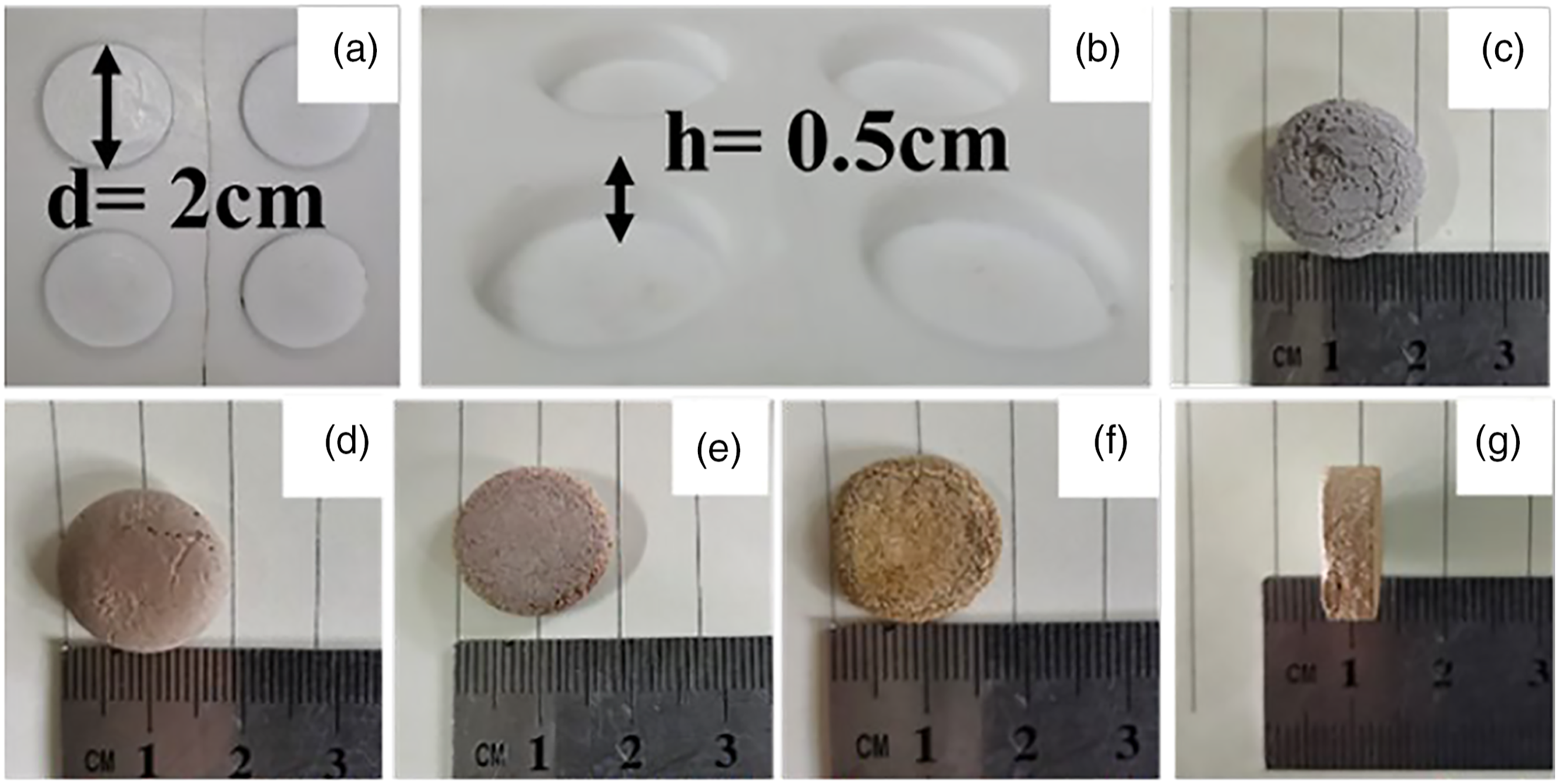
XRD and IR analysis of porous t-BaTiO3/Ag/β-PVDF
XRD patterns of the porous t-BaTiO3/Ag/β-PVDF composite block and pure PVDF are shown in Figure 2. The blue pattern in the picture was the diffraction peak of pure PVDF used in the composite block. The diffraction peak of the composite block was corresponded with the diffraction peak of the tetragonal phase BT (JCPDS No. 05-0626), and a split diffraction peak at 2θ ∼ 45° can be seen in the insert pattern. By comparing the XRD patterns of the porous t-BaTiO3/Ag/β-PVDF composite block and pure PVDF, a large peak 2θ = 20.7° corresponded to (100) and (200) was β-phase of PVDF, and another intensity peak observed at 38.0° corresponded to (021) was α-phase of PVDF.
16
No obvious PVDF diffraction peak was observed in the block after composite. The possible reason was that the poor crystallization of PVDF itself and the porous structure.
17
This will also cause the diffraction peaks of the composite material to have a higher signal-to-noise ratio and affect the crystallinity of the entire composite material. The content of Ag was small, which not reflected in the diffraction peaks of the composite block. XRD patterns of the porous t-BaTiO3/Ag/β-PVDF composite block and pure PVDF.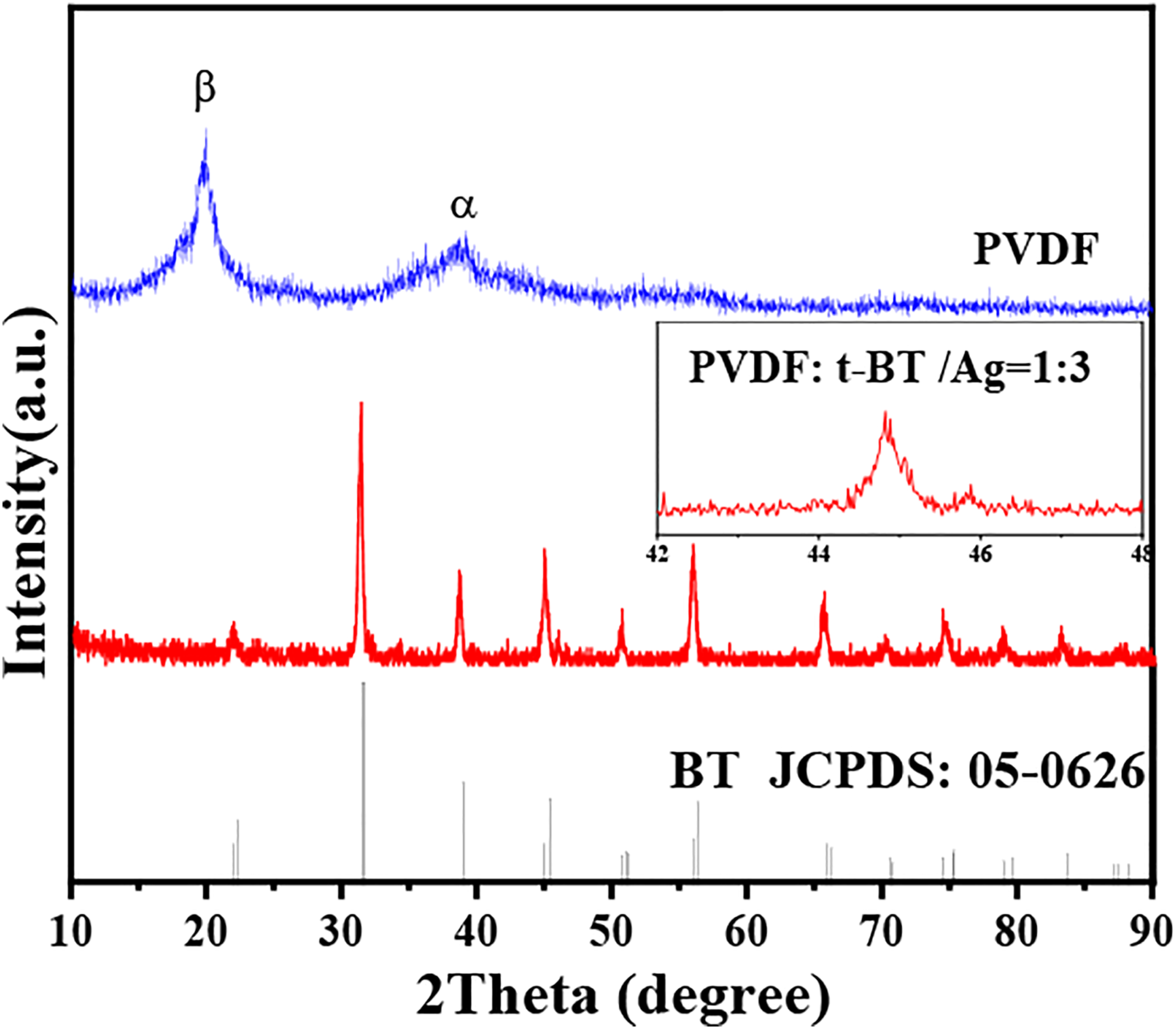
In order to further confirm the composites, the IR was used to study. The IR pattern of the porous BT/Ag/PVDF composite is shown in Figure 3. The presence of β-phase PVDF in the composites can be characterized by IR pattern. The peaks at 3423 cm−1 corresponded to the -OH stretching vibration due to reaction system of the t-BT/Ag was obtained at a NaOH system, the -OH group in the powder was obvious. However, t-BT/Ag compounded with PVDF, the -OH vibration in the IR pattern was weaker than before. The vibrational peaks was located at 840 cm−1, 878 cm−1 corresponded to the β-phase of PVDF.
18
The peaks at 1635, 1528, 1410 cm−1 were attributed to -C=O, -C=C-, and -CH2- stretching.
19
The weak characteristic peak appeared about at 1350 cm−1 was related to the Ag-O vibration.20,21 The vibrational peaks located at 427 and 565 cm−1 are mainly attributed to Ba-O and Ti-O bond, suggested the formation of crystallized BaTiO3.22,23 The above results were proved the successful preparation of the t-BaTiO3/Ag/β-PVDF composite. IR patterns of the porous t-BaTiO3/Ag/β-PVDF composite block and t-BaTiO3/Ag.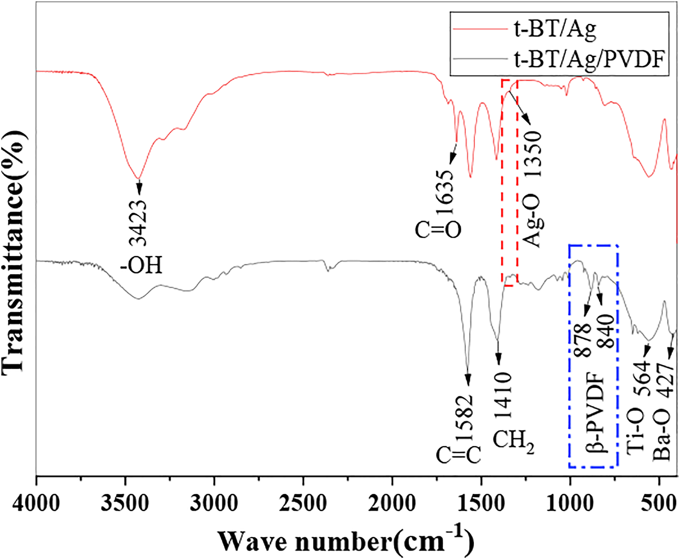
SEM analysis of porous BT/Ag/PVDF
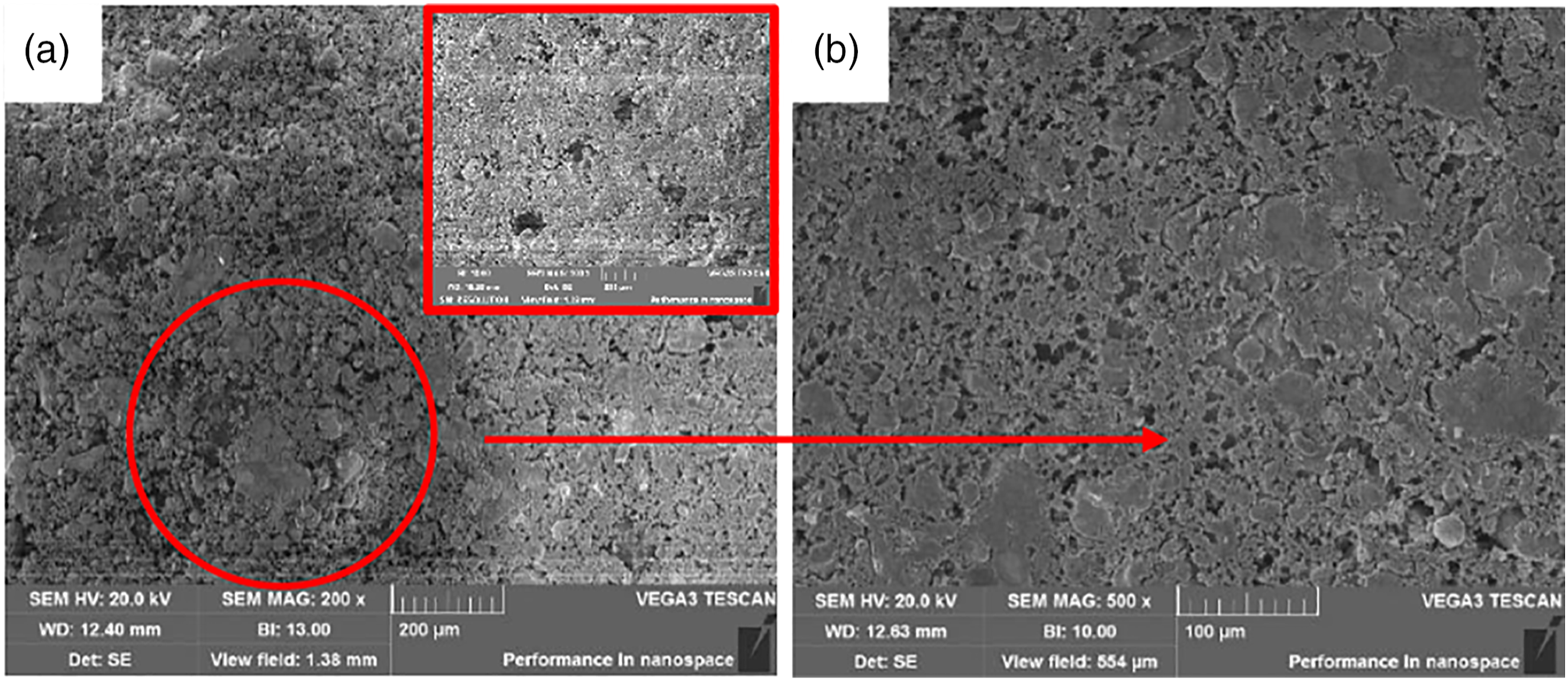
The morphologies of porous t-BaTiO3/Ag/β-PVDF composite are shown in Figure 4. The surface of composite has some porous because the NaCl was dissolved and washed out by deionized water in Figurer 4(a). The cross-sectional view of the composite in Figure 4(b) showed many pits, which further indicated that the internal NaCl was completely disappeared and the desired porous morphology was obtained. From the high magnification of the cross-sectional view in Figure 4(c) and (d), the polymer PVDF like a gel wrapped the t-BT/Ag particles. Meanwhile, the PVDF acted as a bridge and supported to connect the t-BT/Ag particles into a whole block, ensuring the appearance of the porous channel, which also played a fixed role, ensuring that the porous appearance was not destroyed during use. SEM image of t-BaTiO3/Ag/β-PVDF composite block. (a, b) 200x, (c) 3000x, (d) 8000x.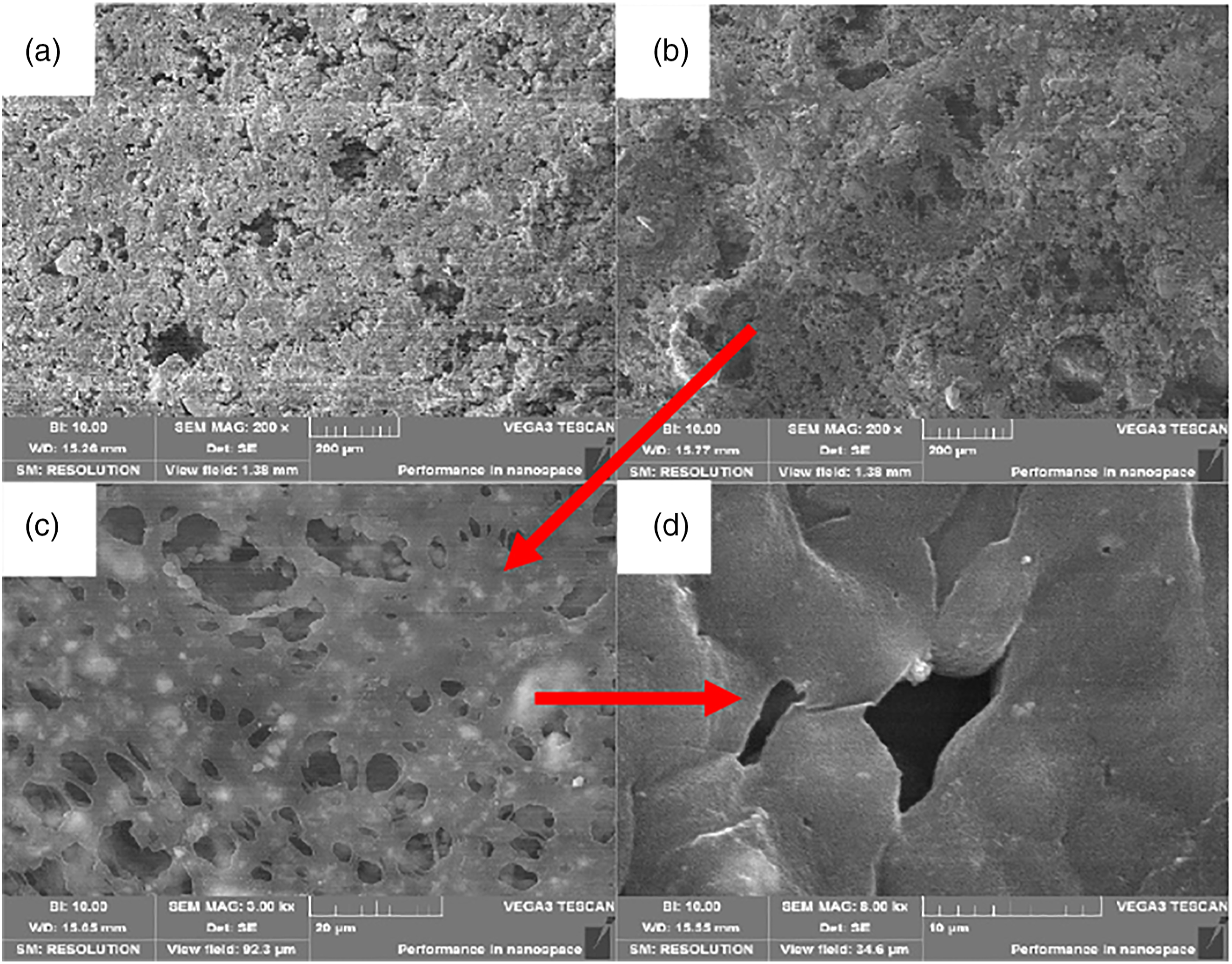
Analysis of electrical properties of porous t-BaTiO3/Ag/β-PVDF
In order to study the photocatalytic activity of the prepared samples as t-BT/Ag, c-BT/Ag, t-BT/Ag/PVDF, and c-BT/Ag/PVDF were used as photocatalysts to perform photodegradation reactions on methyl orange (MO) and rhodamine B (RhB) solutions under ultraviolet light irradiation, as shown in Figure 5. Samples reached the adsorption–desorption equilibrium in the dark reaction for 30 min, then using UV photocatalysis for 120 min, and taking a measurement point every 30 min. The t-BT/Ag, c-BT/Ag, t-BT/Ag/PVDF, and c-BT/Ag/PVDF composites degraded 94.8%, 47.3%, 37.1%, and 17.4% in 120 min in MO system, and degraded 60.9%, 22.7%, 24.6%, and 11.4% in 120 min in RhB system, respectively. The results indicated that t-BT/Ag degradation effect was higher than that of c-BT/Ag, the porous t-BaTiO3/Ag/β-PVDF was higher than that of c-BT/Ag/PVDF. It showed the effect of the tetragonal phase was higher than that of the cubic phase, whether in the MO or RhB system. The reason is that the high recombination rate of the electrons and holes in the cubic phase BT which decreased its photocatalytic activity.
5
The photocatalytic degradation of t-BT/Ag powder, c-BT/Ag powder, t-BT/Ag/PVDF and c-BT/Ag/PVDF porous t-BaTiO3/Ag/β-PVDF. (a, b) Degrade MO, (c, d) Degrade RhB.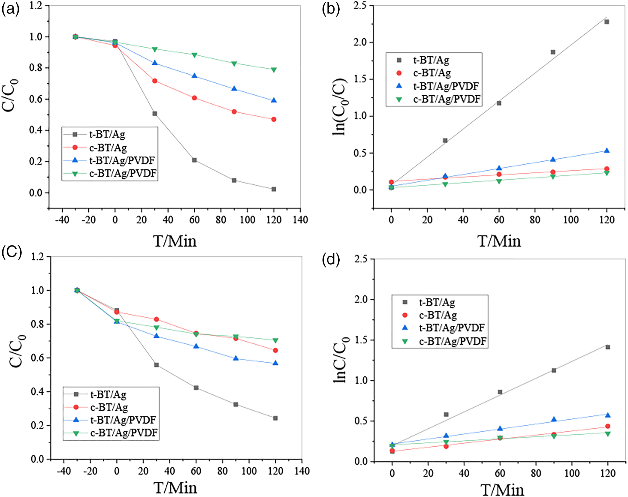
The photocatalytic activity can be quantitatively evaluated according to the Langmuir–Hinshelwood kinetic model by comparing the reaction rate constant. The formula is ln(C0/C) = kt, where C is the concentration of RhB or Mo at the irradiation time of t, C0 is the initial concentration of RhB or MO solution, k is the rate constant of reaction. The first-order linear fitting of the photodegradation efficiency of MO (Figure 5(b)) and RhB (Figure 5(d)) solution irradiated by UV light under the different photocatalysts. With the addition of t-BT, c-BT/Ag, t-BaTiO3/Ag/β-PVDF, and c-BT/Ag/PVDF, the rate constant photocatalytic degradation of MO solutions was k = 0.01898 min−l, k = 0.00143 min−l, k = 0.00399 min−l, and k = 0.00168 min−l, respectively. The rate constant photocatalytic degradation of RhB solutions was k = 0.01038 min−l, k = 0.0025 min−l, k = 0.00307 min−l, and k = 0.00124 min−l, respectively. The results showed that cubic phase samples were lower than the tetragonal phase samples while the bulk samples were weaker than power sample. The reasons may be as follows: First, the quadrangular structure has an asymmetric structure, which can form an internal electric field and promote the increasing surface charge, leading the active point on the surface. Second, PVDF coating can limit the catalytic effect of tetragonal phase bulk sample.
Piezoelectric photocatalytic properties analysis of porous t-BT/Ag/PVDF
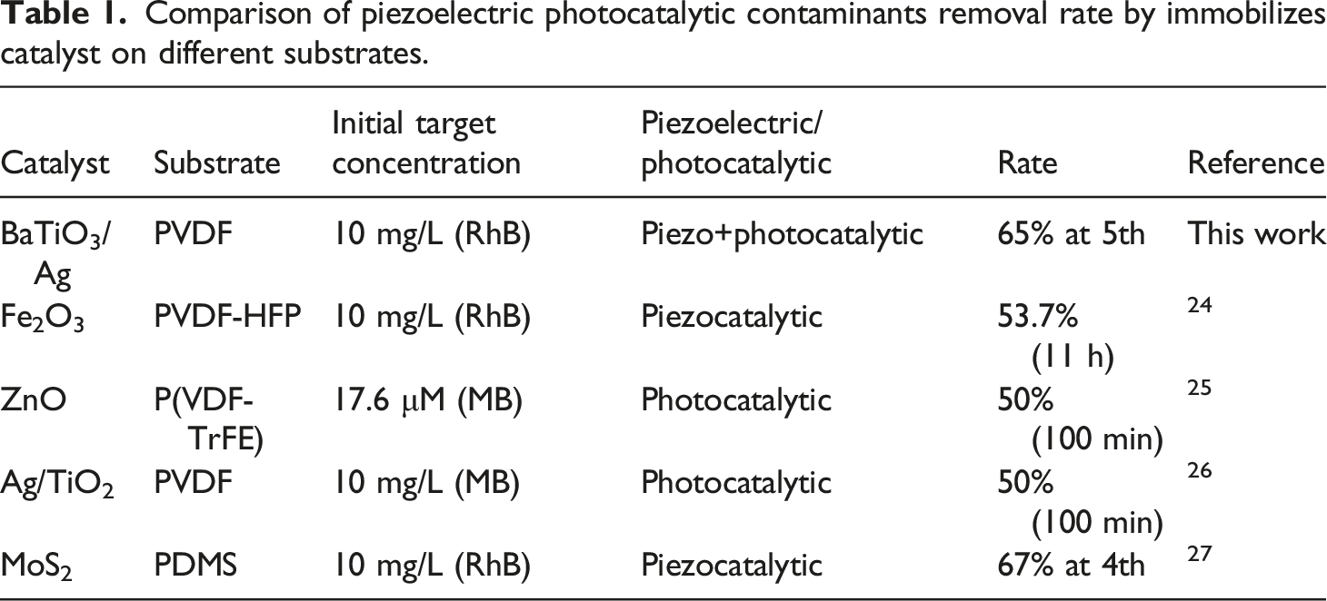
Before characterizing the piezoelectric catalytic property, the porous t-BT/Ag/PVDF was polarized with 110°C for 20 min. The selected polarization voltage was 15 KV during the polarization process. After polarization, the sample could stand for 24 h for aging, and then the catalytic property was tested. The degrade concentration of MO or RhB was 10 mg/L. The ultrasonic frequency was 40 KHz and 120 W in this experiment and the entire experimental system was carried out under dark conditions, and the results are shown in Figure 6. The MO degraded by pure UV light was 14.7% for 120 min without catalyst. Before polarization in pure ultrasound (US), the porous t-BT/Ag/PVDF degrades MO only 13.1%, and US+polarization (POL) was degraded at 19.1%, moreover, US+UV+POL was degraded at 56.4% within the same time of 120 min in Figure 6(a). The Figure 6(b) showed that the degradation rate of pure US without UV and POL (US) was k = 0.00206 min−l, US and UV (US+UV) was k = 0.00144 min−l, US and POL (US+POL) was k = 0.00213 min−l, US, UV, and POL (US+UV+POL) was k = 0.00583 min−l, respectively. All the results showed that the polarization sample was higher than that of no polarization, indicating that the electrical domains could be aligned in the direction of the electric field through polarization, which made it easier to perform piezoelectric catalysis. 45.1% MO degradation can be obtained in the same time applying ultraviolet light and ultrasound to the composite block at the same time, which is higher than the piezoelectric catalysis (19.1%) under pure ultrasound and the photocatalysis under pure ultraviolet light (37.1%). For the RhB system, it can be seen from Figure 6(c) that the piezoelectric catalytic effect of the composite block degrades RhB at 20.5% in US, 51.4% in POL, 52.6% in UV+POL, and 65% in UV+US+PL for 120 min. The Figure 6(d) results showed that the degradation rate of pure US (US) was k = 0.00206 min−l, US+UV was k = 0.00230 min−l, US+POL was k = 0.00798 min−l, US+UV+POL was k = 0.00912 min−l, respectively. Through the comparison of degradation effects, it is concluded that the piezoelectric photocatalytic effect of the t-BaTiO3/Ag/β-PVDF composite block is higher than that of pure piezoelectric catalysis and photocatalysis. These results in Table 1 indicated that the porous composite t-BaTiO3/Ag/β-PVDF had a better piezoelectric and photocatalytic response than the Fe2O3/PVDF-HFP porous film,
24
ZnO/P(VDF-TrFE),
25
Ag/TiO2/PVDF,
26
and same as MoS2/PDMS.
27
It is showed that the combination of t-BT/Ag and PVDF will promote piezoelectricity. The effect generates carriers will be improved the overall catalytic effect. Piezoelectric catalysis of t-BaTiO3/Ag/β-PVDF composite degradation of the system MO (a, b), and RhB (c, d). Comparison of piezoelectric photocatalytic contaminants removal rate by immobilizes catalyst on different substrates.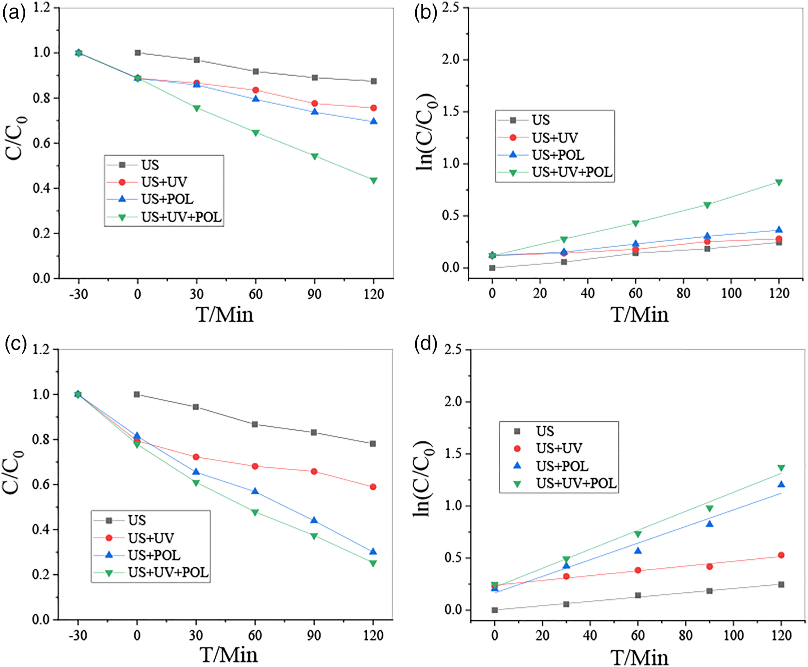
Stability analysis of t-BT/Ag/PVDF composite block
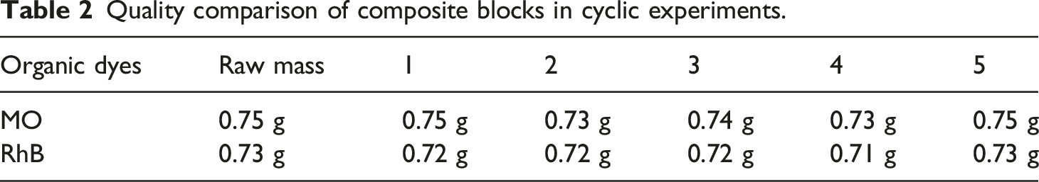
The composite block is more convenient use recycling. However, the well stability and reliability of samples during the use process is an important requirement. The stability of the t-BaTiO3/Ag/β-PVDF composite block was analyzed. A cycle experiment was performed on the piezoelectric photocatalytic degradation experiment of the polarized composite block, and the degradation comparison diagram of five cycles is shown in Figure 7. In the cyclic experiment, the concentration of the degraded MO and RhB is 10 mg/L, and the same composite block was used for degradation each time. The frequency of ultrasound used was 40 KHz and 120 W. It can be seen that after five cycles of degradation of MO (Figure 7(a)) and RhB (Figure 7(b)), the degradation effect is basically stable, and still maintains good photocatalytic performance, which indicated that the composite block had a good performance in catalytic degradation. Meanwhile, the weight of the composite block after five cycles is shown in Table 2. The composite block quality has not been changed. The corresponding SEM analysis was performed on the composite block after the cycle as seen in Figure 8. Compared with that before the cycle (thumbnail of Figure 8(a)), the SEM image of Figure 8(b) under 200x was basically no change, the surface of the block was relatively flat. Combined with 500x, there was no cracking and pore damage. Lin et al.
27
reported the composite of MoS2 nanoflower/PDMS degraded Rhodamine B using its piezocatalytic activity. The results showed that the piezocatalytic activity of composite was mainly from the MoS2 on the surface of PDMS. When the composite was used several times in water, MoS2 particles fell off from the surface of the material, resulting in a decrease of activity. Therefore, the composite block of t-BaTiO3/Ag/β-PVDF can still maintain the integrity and ensure the reliability in future use. Piezoelectric photocatalytic degradation cycle diagram of porous t-BaTiO3/Ag/β-PVDF after polarization (a) degradation of MO and (b) degradation of RhB. Quality comparison of composite blocks in cyclic experiments. SEM image of t-BT/Ag/PVDF composite block after cyclic degradation. (a) 200x and (b) 500x.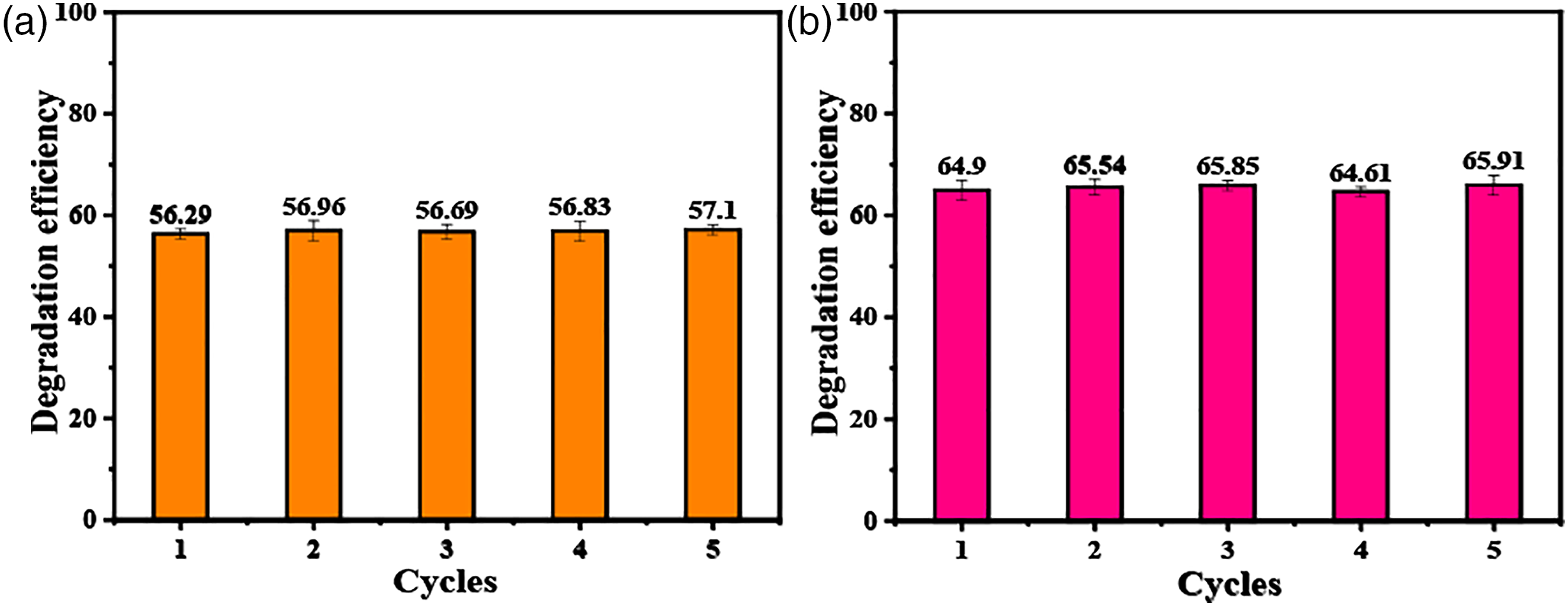
Piezoelectric property and simulation calculation of t-BT/Ag/β-PVDF composite block
A quasi-static d
33
measuring instrument was used to conduct of t-BaTiO3/Ag/β-PVDF, t-BT/Ag, and PVDF blocks. Before the test, three kinds of blocks were polarized, and then the average value was measured 10 times for each block. The result is shown in Figure 9. The d
33
of t-BT/Ag, t-BaTiO3/Ag/β-PVDF and PVDF was 1.86 pC/N, 1.44 pC/N, and 0.2 pC/N, respectively. Piezoelectric constant d
33
of t-BaTiO3/Ag/β-PVDF, t-BT/Ag and PVDF.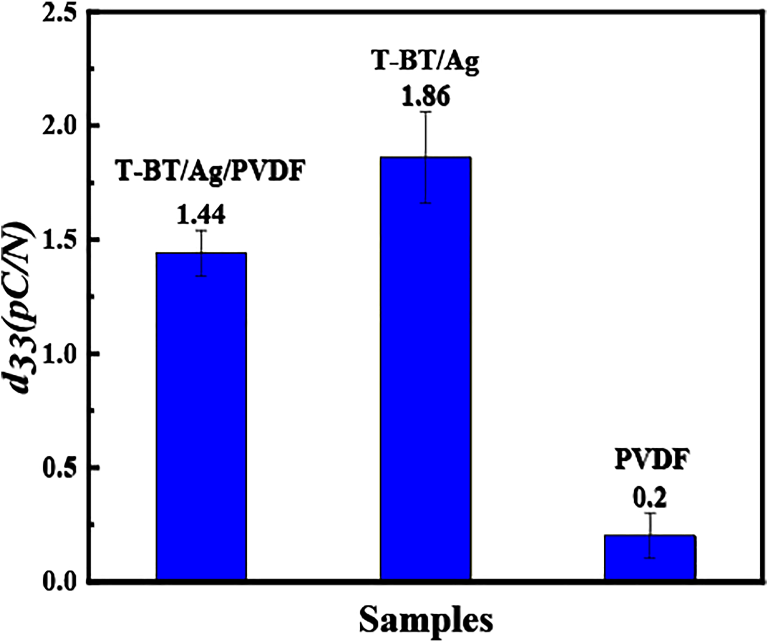
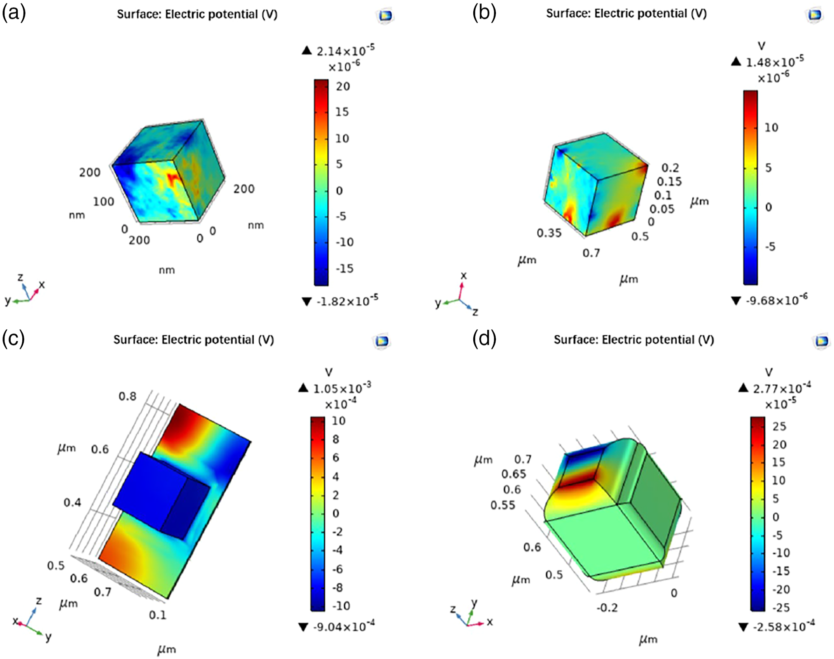
The piezoelectric potential of the same volume of t-BT/Ag is higher than that of PVDF. In order to clarify the piezoelectric synergy of t-BT/Ag and PVDF in composite materials, finite element simulation software (COMSOL) was used to model the t-BT/Ag/PVDF composite block. Compared to the SEM images of the composite block, it showed that PVDF was a key role of bridging and supporting, t-BT/Ag and PVDF can be roughly divided into two types: t-BT/Ag attached to PVDF and t-BT/Ag wrapped by PVDF. Based on the two types, a model was established as shown in Figure 10. The small size of the Ag particles on the surface of the t-BT, and the t-BT/Ag powder was chosen as a cube with an overall side length of 200 nm in Figure 10(a), which was consistent with the size of the t-BT/Ag particle SEM image. Meanwhile, the PVDF was modeled with a cube of the same size, and the modeled image was shown in Figure 10(b). The t-BT/Ag was attached to the surface of PVDF in Figure 10(c) and the t-BT/Ag was wrapped by PVDF in Figure 10(d). After the model was builder, the physics was sited. The simulation calculation was the piezoelectric potential after polarization of t-BT/Ag and PVDF, respectively. At this time, the choice of physical field was the coupling of solid mechanics and electrostatic field, and the choice was polarization on the Z axis, the calculation diagram as shown in Figure 11. The piezoelectric potential of t-BT/Ag was 2.14 × 10⁻⁵ V, the PVDF was 1.48 × 10⁻⁵ V, the t-BT/Ag attached to PVDF was 1.05 × 10⁻³ V, the t-BT/Ag wrapped by PVDF was 2.77 × 10⁻⁴ V. It showed that the piezoelectric potential of t-BT/Ag was higher than that of PVDF, and the piezoelectric potential of t-BT/Ag attached to PVDF was higher than that of t-BT/Ag wrapped by PVDF. Modeling diagram of t-BT/Ag and PVDF. (a) t-BT/Ag modeling (blue), (b) PVDF modeling (gray), (c) t-BT/Ag adhered to the PVDF, and (d) t-BT/Ag was wrapped by PVDF. Polarization piezoelectric potential simulation diagram. (a) t-BT/Ag, (b) PVDF, (c) t-BT/Ag attached to PVDF, and (d) t-BT/Ag wrapped in PVDF.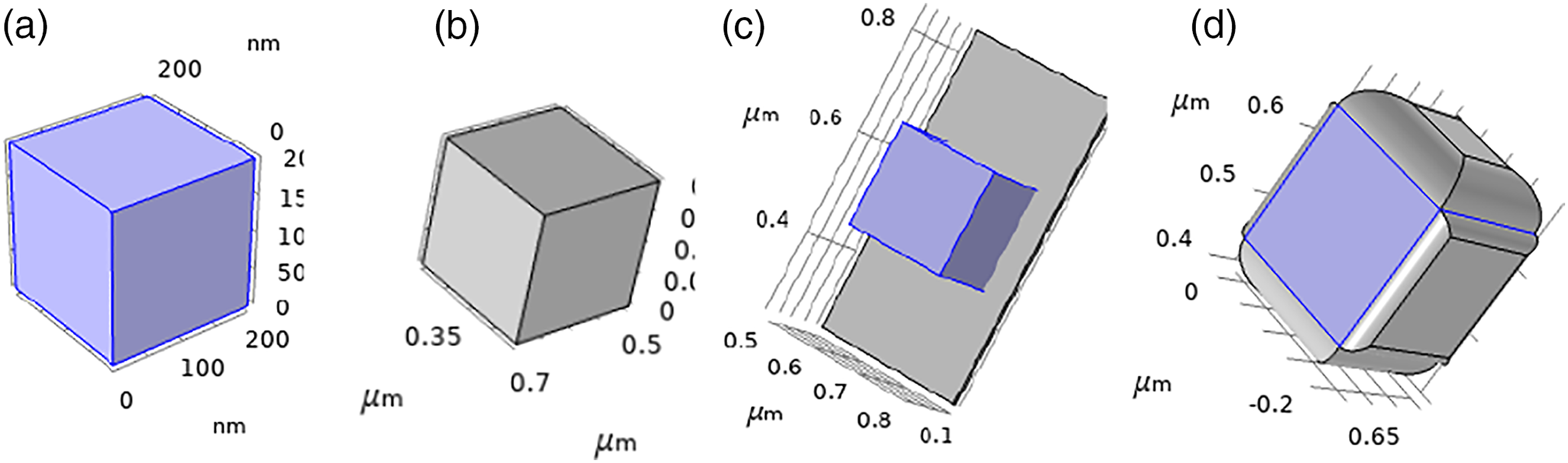
Then the piezoelectric potential of t-BT/Ag and PVDF under the condition of applying ultrasound after polarization was simulated and calculated. The piezoelectric potential generated by the impact force acting on the piezoelectric material can be calculated by the physical field of acoustic-solid piezoelectric action under the acoustic module.
28
The results are shown in Figure 12. It is indicated that he piezoelectric potential of t-BT/Ag was 1.18 × 10⁻³ V, the PVDF was 2.68 × 10⁻⁴ V, the t-BT/Ag attached to PVDF was 0.04 V, the t-BT/Ag wrapped by PVDF was 0.08 V. The trend was the same before ultrasound, the piezoelectric potential of t-BT/Ag was higher than PVDF. The piezoelectric potential of t-BT/Ag attached to PVDF was higher than that of t-BT/Ag wrapped in PVDF. The reason may be that piezoelectric materials can easily deform under mechanical external forces to generate electric charges. It can be explained that when t-BT/Ag was wrapped by PVDF, the piezoelectric potential generated was smaller than which was adhered to PVDF. The wrapping may limit the deformation of the material, which cannot exert its piezoelectric properties fully. However, recycling after compounding is beneficial, and the overall material properties after compounding can satisfy the use. The simulation results showed t-BT/Ag and PVDF can play a good synergistic effect, and the piezoelectric potential is higher than that of the single individual. Polarization and ultrasound piezoelectric potential simulation diagram. (a) t-BT/Ag, (b) PVDF, (c) t-BT/Ag attached to PVDF, (d) t-BT/Ag wrapped in PVDF.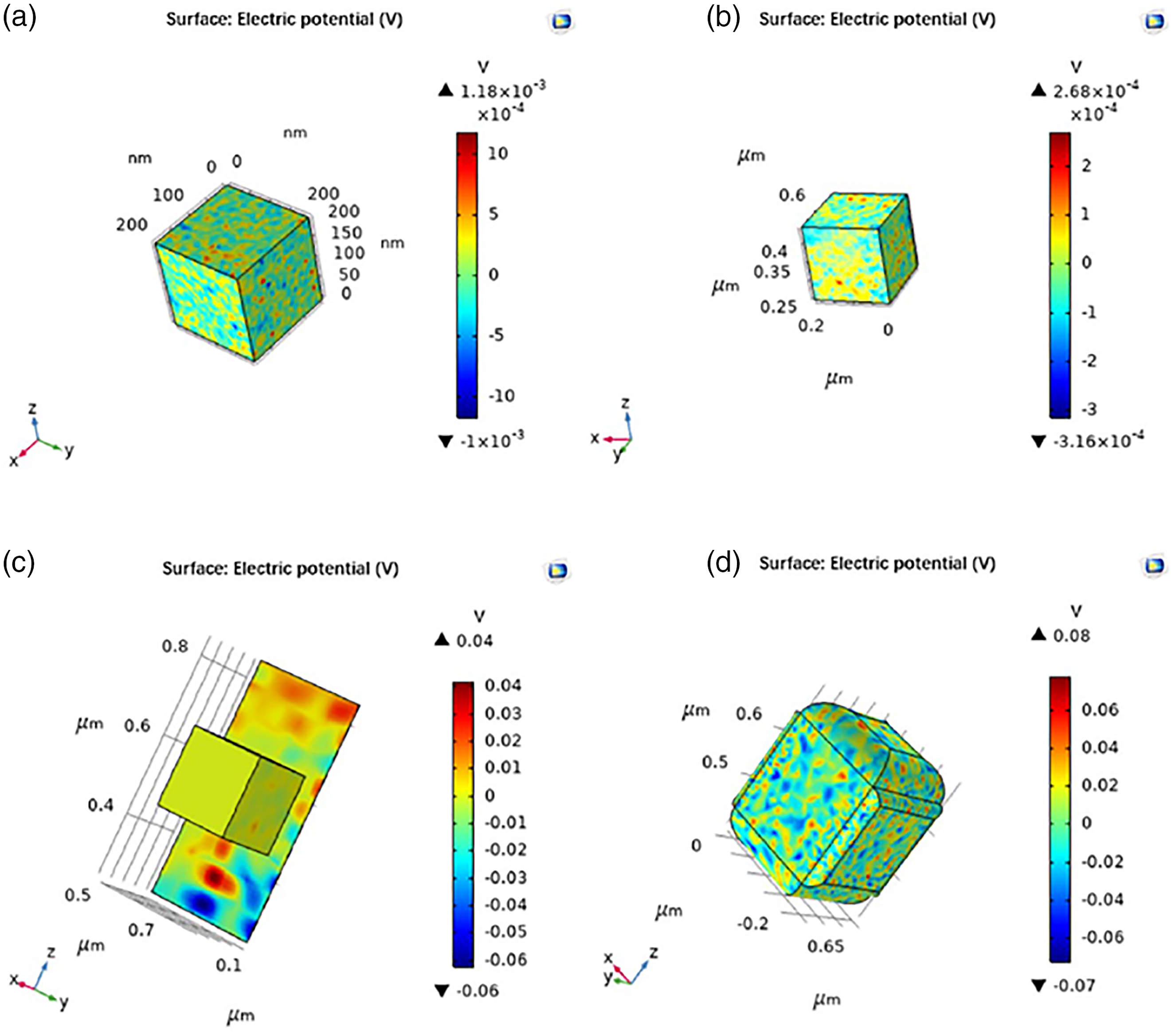
Mechanical property and porosity analysis of t-BT/Ag/β-PVDF composite block
The mechanical properties of the composite block were tested by the stress-strain curve, as shown in Figure 13. The deformation of the composite block was 30%, while the stable work cannot be performed in Figure 13(a). The porous material has not been recycled and entered the linear elastic stage, the force was 2.54 MPa with the deformation reached 30%, and there was no yield platform between 30 and 40% deformation. After the cycle, the deformation reached 30% and the force was 1.04 MPa. It showed that the cyclic use will affect the mechanical properties of the composite block, but the stress–strain curve also indicated that the composite block still had certain mechanical properties, which can ensure the safety and stability during use. Meanwhile, the stress–strain curve of composite block with a height-to-diameter ratio of 1.4:1, is shown in Figure 13(b). The yield point appeared at 1.76 MPa. Compared with the two samples and the cycle SEM image, composite block could maintain its own integrity during the recycling process, and could ensure reliable catalytic performance. Stress–strain curve of t-BaTiO3/Ag/β-PVDF composite block. (a) Height-to-diameter ratio of 1:4 and (b) height-to-diameter ratio of 1.4:1.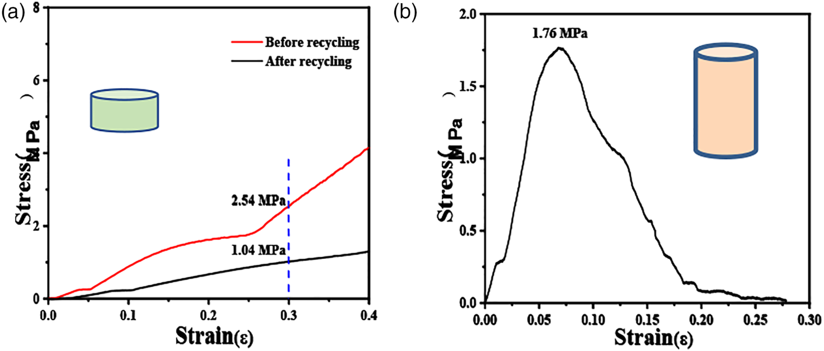
The porosity of t-BaTiO3/Ag/β-PVDF composite block could be calculated by the following formulas: ρ1—ρ of t-BaTiO3/Ag/β-PVDF; ρ
2
—ρ of t-BT/Ag; m
1
—m of t-BaTiO3/Ag/β-PVDF; m2—m of t-BT/Ag; v1—v of t-BaTiO3/Ag/β-PVDF; v1—v of t-BT/Ag


The porosity of t-BaTiO3/Ag/β-PVDF composite block was 70.4%, which met the expected porous block requirements. The porous morphology can increase the using of light and maintain the transmission of light and force.
Growth mechanism for t-BT/Ag/β-PVDF composite block
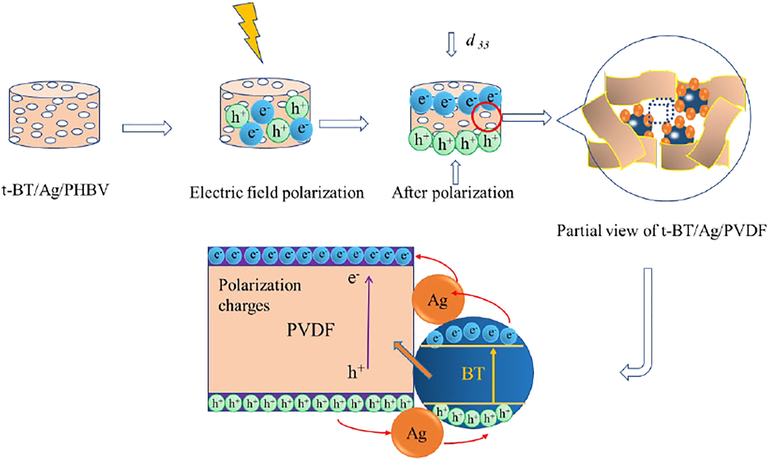
From the above results, a schematic illustration of t-BaTiO3/Ag/β-PVDF composite block growth procedure is shown in Figure 14. The results indicated that the t-BT/Ag and PVDF were mixed. The NaCl appeared in the gap of t-BaTiO3/Ag/β-PVDF composite block. After NaCl was washed out, a lot of vacancies in the position occupied, and finally a porous composite block can be obtained. A possible electron transfer diagram after polarization is shown in Figure 15. After the formation of the porous t-BaTiO3/Ag/β-PVDF composite block, the internal charges were disorderly arranged, and the charges were ordered along the polarization direction after the polarization of the external electric field. Meanwhile, the PVDF in the composite block were β-phase according with the IR result, the piezoelectric charges were generated due to the change in dipole moment. The surface charges on the composite block were produced by piezoelectric polarization and an electric field inside the t-BaTiO3/Ag/β-PVDF composite block was build. The free electrons were driven by built-in electric field, and then traveled along the transmission chain formed by PVDF, thereby, an electron path was formed. Schematic illustration of the growth procedure for the t-BaTiO3/Ag/β-PVDF composite block. The charges transfer process in the t-BaTiO3/Ag/β-PVDF composite block.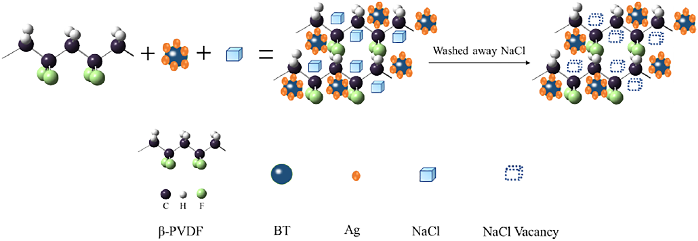
Conclusions
In this paper, the porosity of porous t-BaTiO3/Ag/β-PVDF was obtained when NaCl particles was about ∼70.4%. The compressive strength of t-BaTiO3/Ag/β-PVDF is 1.76 MPa. The piezoelectric coefficient d 33 is 1.44 pC/N, and the results can be explained by COMSOL simulation calculation. The results of degradation MO and RhB showed that t-BaTiO3/Ag/β-PVDF composite material had good degradation and cycle stability. The piezoelectric photocatalytic, mechanical, and electrical properties can basically meet the requirements as a substitute material for environment.
Footnotes
Acknowledgments
This work was supported by the Natural Science Basic Research Foundation of Shaanxi Province (No. 2020JQ-626) and the National Natural Science Foundation of China (No. 51372199).
Declaration of conflicting interests
The author(s) declared no potential conflicts of interest with respect to the research, authorship, and/or publication of this article.
Funding
The author(s) disclosed receipt of the following financial support for the research, authorship, and/or publication of this article: This work was supported by the Natural Science Basic Research Foundation of Shaanxi Province (No. 2020JQ-626) and the National Natural Science Foundation of China (No. 51372199).