
Abstract
In this century, innovation and technology are required to fabricate the hybrid joint of metal and polymers. Due to their lightweight and anti-corrosion properties, the mixed components are increasingly used to produce lightweight hybrid structures such as aerospace and automobiles. It is essential to develop welding techniques for joining dissimilar materials and instead use them in engineering structures. The bonding mechanism of the weld joint has varied depending upon the welding process. In the present review, the bonding mechanism of various hybrid joints like Friction stir welding (FSW), Friction stir spot joining, Friction riveting, laser welding, ultrasonic welding and induction welding is discussed in detail. The defects observed in the different welding process is discussed in details. The mechanical properties and microstructure analysis of different hybrid joints are reviewed in detail for a different combination of hybrid joints.
Keywords
Introduction
The dissimilar joining of metals and polymers has lately received a lot of interest. In order to create hybrid constructions with better structural characteristics for the automotive, aerospace, and marine sectors.1,2 Commercial steel was initially replaced in these industries by lightweight aluminium and magnesium. 3 In addition, polymer and composite materials, as well as aluminium alloy and magnesium, were employed in the design of hybrid body structures.4–6 Polymers are well-known for their low density, high stiffness, resistance to corrosion, and fatigue performance.7–9 Metals, on the other hand, cannot be entirely replaced by polymers due to their tremendous strength, durability and rigidity at high temperatures.6,10
Metal to polymer hybrid implants, including as ear and eye implants, microelectro mechanical systems, and prostheses, are becoming increasingly common in the medical field. The weight-to-strength performance of any component used in the automobile, aerospace, and marine industries is directly related to the fuel efficiency of these hybrid structures. 11 Joining techniques of the fabrication of hybrid metal-polymer structure need further research before implementation. 12 The dissimilarity in thermal, chemical, and mechanical properties of the dissimilar materials the joining of these dissimilar combination is complicated.13,14 Metal to plastic and metal to Carbon fiber reinforced polymer (CFRP) materials have traditionally been joined by using adhesives, mechanical riveting such as rivets and bolts, and hybrid bolted bonded composite joints.
Adhesive bonding is a traditional solid-state process of joining two materials by mechanical interlock, chemical and physical adsorption. 15 Adhesive bonding has received increasing attention in recent years due to its high strength joints that can withstand loads. This method was used in aerospace and automobile applications to reduce overall structural weight and almost joining of all metal, ceramic, and polymer. 16 It also prevents from galvanic and crevice corrosion between two dissimilar materials.
Carbon fiber reinforced polymer composites is used in BMW i3 and i8 bonded to aluminum alloy with adhesives.4,17 It is a highly flexible method, but it requires proper surface treatment for better joining and a long curing time during the joining process. Furthermore, adhesive joints are susceptible to thermal degradation due to factors such as moisture, humidity, and high temperatures. Joint disassembly is difficult because it is an irreversible process that causes material damage.
Nonetheless, mechanical fastening has several advantages over adhesive joining, including ease of assembly and disassembly, reparability, and resistance to environmental effects.18–23 Bolted joints, on the other hand, still have a number of disadvantages like stress concentrations in the fastener hole, 24 as well as undesirable damages such as delamination and micro buckling caused by drilling holes, which reduces the strength and performance of the joints. 25 Furthermore, selecting an adhesive that performs well for both metal elements and polymer, but appropriate surface treatment needed for sound joining, is a difficult and time-consuming process.26–28
Welding technologies can resolve adhesive bonding and mechanical joining problems. It facilitates in the mass production of short cycle time joints between aluminium and polymer materials. However, the mechanism for joining metal and polymer remains to be explored. The primary goal of this article is to investigate various welding processes for aluminium alloys and polymers that have been reported thus far, and to compile information on mechanical characteristics, bonding mechanisms, and microstructural characterisation of various welding methods with distinct dissimilar hybrid joints. This article helps the researchers to overcome the limitations associated with dissimilar hybrid joining of various materials.
Welding
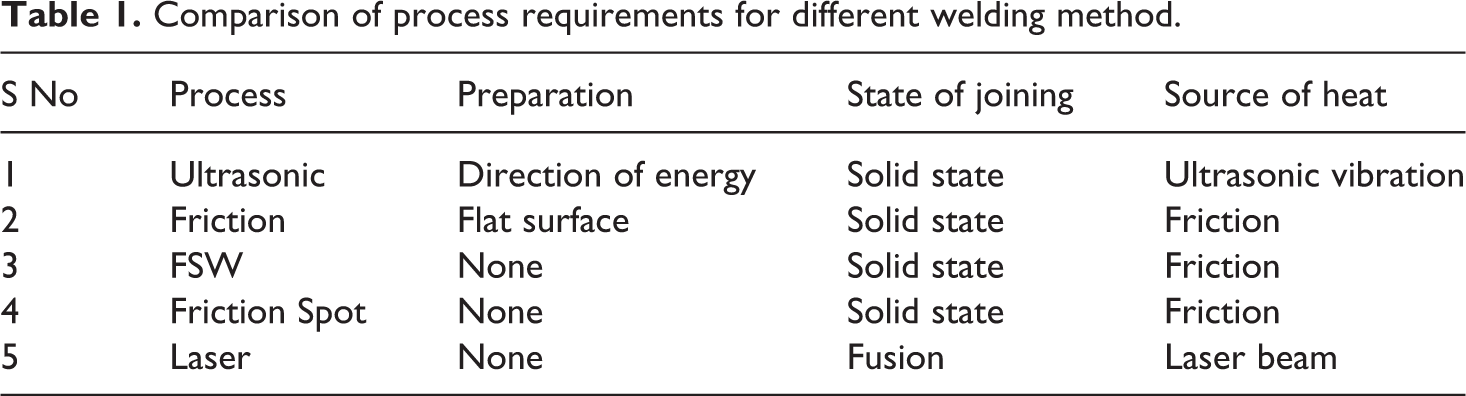
Welding is a manufacturing process that uses heat and pressure to join metals, thermoplastics, and composites. The most appropriate welding technologies for connecting dissimilar metal to polymer hybrid structures include friction stir welding (FSW), laser-based welding, friction stir spot welding (FSSW), and ultrasonic welding. 29 Welding methods usually involve three processes. a) molten material formation b) bonding formation c) molten material cooling with time. 30 Laser welding uses a concentrated heat source on the base metal to produce narrow and deep welds.31,32 No filler material is required, for stable welding it should be automated. 33 High power density and high production rate are advantageous for industrial applications such as steel structure, engine parts, automobile body parts, and interiors.34–36 Solid state welding, on the other hand, uses low heat and does not melt the base metal.37,38 It is typically used to weld aluminium alloys and polymers.39,40 The rotating tool plunges into the base material during friction stir welding. The probe that propagates through the base material is the main feature of the FSW tool. 41 Produces less heat below the recrystallization temperature. 42 FSW is mainly used for long straight weld in aerospace, marine and automotive industrial application for creating lighter and economical structures.43,44 Because less heat is produced, there is no cracking and little distortion of the base material. 45 Table 1 depicts various welding processes and their requirements.
Comparison of process requirements for different welding method.
Friction stir welding
Bonding mechanism
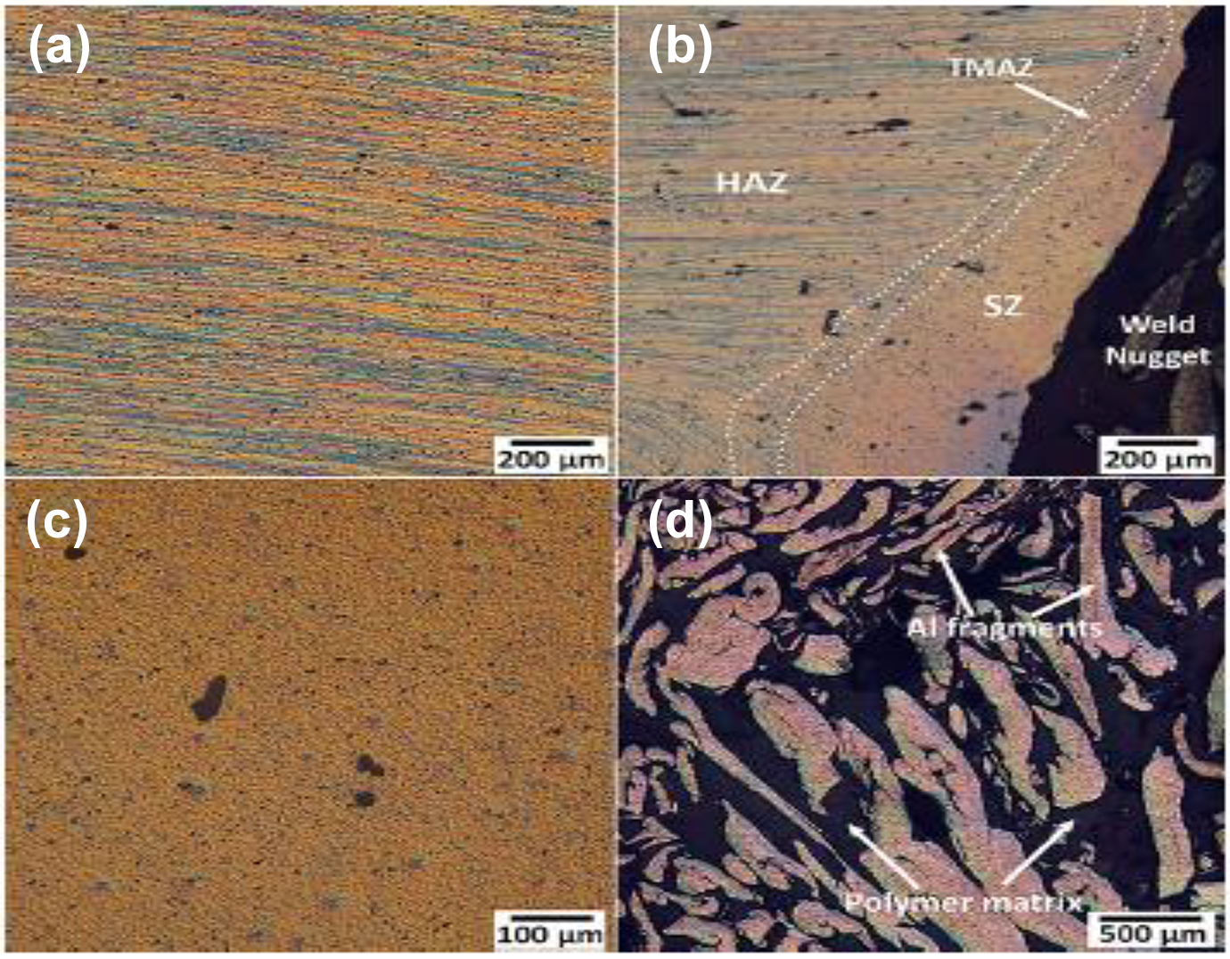
A stirring tool is plunged into the surface of the base metal and travels along a path of joint during the process of FSW. The rotating tool not only generates heat as it presses through the surface of the base plate and mixes it with the base material in the stir zone, but it also applies pressure to the joints. 46 Heat makes the materials plasticize below the melting point and flow in the hole left behind the tool pin. The molten layer is under adhesion and interlocking between the dissimilar materials. Macro mechanical interlocking and chemical adhesion bonding ascribed to the main bonding mechanism in Friction stir welding technique. 47 Bonding between both materials ensures strength of the dissimilar welded joints. 48 Proper bonding and surface interlocking are necessary for a good sound weld. Rotating tool helps in the formation of Al chips in the weld stir zone by movement of tool along the bonding line. 49 Aluminum fragments found in the stir zone shown in Figure 1 shows the schematic diagram of FSW and Bonding mechanism of dissimilar metal to polymer. Where the size of Al fragments minimized by increasing the tool rotational speed or by decreasing the tool traverse speed. Lower deformation by heat merely eliminates the oxide layer existing in the surface, whereas higher heat produces mechanical interlocking and forms suitably strong connections. 50 Too much heat may lead to degradation the polymer and weaken the joints. Advantages of this joining technique, they are easily assembled and used, does not need any filler material during joining. However, only a few studies have been performed using this technique to join dissimilar hybrid metal to polymer joints. 51
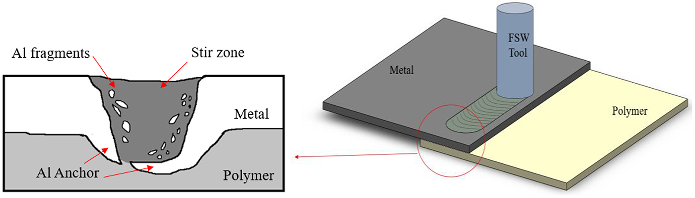
schematic diagram of cross section of FSW and bonding mechanism metal and polymer.
Effect of FSW tool
Tool design has a significant impact on weld joint, which determines material flow and joint strength.52,53 The major challenge in FSW is the material selection and design of the tool. The tool shape determines the heating, material flow and forge area pattern of the plastic weld.54–56 Tool shape and tool wear are two major properties which may affect the weld quality by heat production and dissipation. The friction between the rotating tool shoulder and work piece is the source of heat generation in the base material. 57
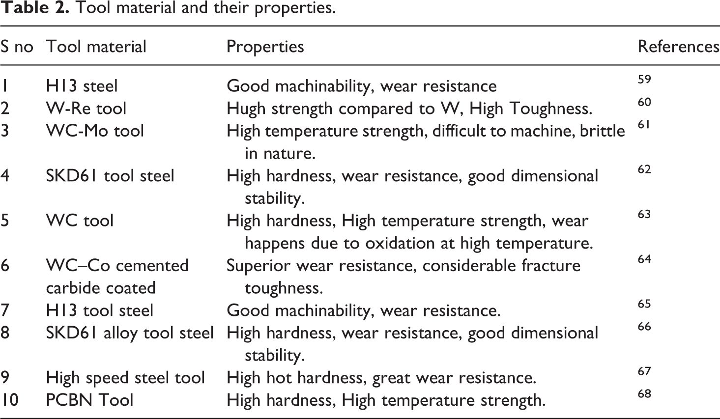
The properties of good tool materials57,58 for FSW/FSP are as follows: Tool wear changes the shape of the tool, hence tool should have good resistance to wear, so that it could avoid degradation of weld quality and defects. It should have good machinability to weld complex structures. Low thermal expansion coefficient to reduce thermal stress. High fracture toughness to avoid breakage while plunging and retracting. Good creep resistance and dimensional stability at elevated temperature.
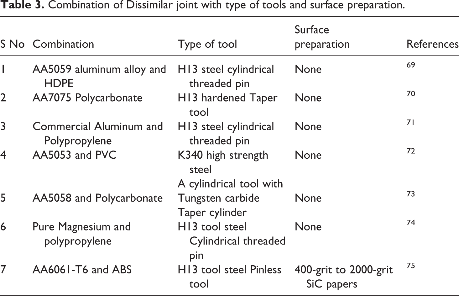
Table 2 lists the various types of tool materials as well as their properties.59–68 Table 3 lists the various types of tools used to join dissimilar metals to polymers.69–75 as reported the result shows that the H13 tool is most often used to weld harder materials and aluminium alloys due to its high wear resistance. High-strength materials are mostly welded using Tungsten (W) and polycrystalline cubic boron nitride (pcBN) based tools. In contrast to other tools, the high hardness and temperature stability of the pcBN tool allows for limited wear. 58 Shoulder to pin diameter of tool plays a crucial role in stir zone development. Diameter of the pin is equals the basemetal thickness and pin length is comparatively shorter than thickness.76,77
Tool material and their properties.
Combination of Dissimilar joint with type of tools and surface preparation.
Effect of FSW process parameters
Tool rotational speed, welding speed, tool dimension, tool tilt angle and tool plunge depth are the most notable friction stir welding process parameters.78,79 Where each parameter plays a major role in stirring and heat generation. Tool rotational speed disturbs the intensity of the plastic deformation which directly reflects in material mixing. 80 The optimization of process parameters is necessary to obtain a good weld joint strength. 81 Xu et al. 75 investigated the influence of welding speed on Friction stir weld on AA6061/ABS, at lower traverse speeds, the working temperature is more than the polymer’s melting temperature which leads to generation of voids in the stir zone region. Liu et al. 82 attempted with the optimum welding parameter to achieving maximum tensile strength without bubbles formation in the welding region and reducing the size of the bubbles by increasing rotational speed, welding speed and plunge depth. Improper selection of FSW metal-polymer welds are susceptible to defects like tunnel defect, cracks, excessive flash and bubble formation due to the improper metal flow and heat generation. Increase in transverse speed guides to increase bonding area & decreases with the further increase in welding speed, it is clear that amount of bubbles reduced with increase in welding speed. 83 At higher transverse speeds no warping and welding distortion in the joints because of low working temperature. 46 Thus the combination of higher welding speed and lower rotational speed or lower welding speed and higher rotational speed leads to better tensile properties, proper weld depends on optimal process parameters.
Tensile strength
Huang et al. 84 investigated joint strength of aluminum alloy 6061-T6 & poly ether ketone produced by Friction stir lap welding and studied that the shear strength of the dissimilar joints measured at various welding speeds. Shear bond strength is directly affected by welding speed, with greater welding speeds resulting in insufficient plasticization of the material. With the increase in tool traverse speed, shear bond strength increases to certain level and then gradually decrease with further improvement of traverse speed. Maximum shear strength of 20.2 MPa is obtained at 50 mm/min due to formation of bigger aluminum anchor and wider bonding area between metal and resolidified polymer were load carrying capacity is more which helps in excellent joint. At higher welding temperature reduction of Al anchor happens which results in progressive decrease in shear bond strength. In another study Huang et al. 85 compared tensile shear strength results with different rotating speeds. They reported that higher tensile strength achieved is 18 MPa at rotational speed 1600 rpm and minimum tensile strength is 10 MPa at rotational speed 1400 rpm. Tensile strength increased with the increase in rotating velocity up to 1600 rpm and decrease with further increase 1800 rpm which reduces the joint strength due to softening of PEEK due to high heat input. A similar study reported in other study Huang et al. 47 of joining AA2060-T8 CF PEEK, the increase in rotational speed the tensile strength rises and subsequently fall. Low velocity ratio the amount of heat generated at the contact surface was inadequate, resulting in poor material stirring and chip formation. Melting and squeezing of high-heat-concentration materials, to get satisfactory outcomes, proper welding settings must be maintained. Patel et al. 86 carried out friction stir welding of aluminum alloy 6061-T6 to polycarbonate and compared the tensile strength for different parameters. The higher tensile strength of 14.913 MPa was acquired with tool rotational speed 500 rpm and feed rate 40 mm/min. Heat input plays major role in tensile properties of the hybrid joints, heat input is highly influenced by rotational speed and welding speed. Increased rotating speed results in increased frictional heat and mechanical stirring, with the increase in temperature fluidity of metal increases which improves weld quality. Graph of relationship between tensile strength and velocity ratio is shown in Figure 2. Derazkola et al. 87 studied tensile strength of FSWed AA5058 and Poly methyl methacrylate. Tool tilt angle and plunge depth plays an important role in ultimate tensile strength. Maximum tensile strength of 45 MPa at rotation speed of 1600 rpm, welding speed of 25mm/min, 2° tilt angle and 0.2 mm plunge depth. Shahmiri et al. 88 carried out Friction stir lap welding of aluminum alloy AA5052-H32 and Polyproplene PP-C30 S and compared shear strength of joint with the pseudo heat index W 2 /V. where, W is the rotational speed and V is the welding speed, they concluded that low heat input results in the maximum shear strength value of 5.1 MPa that 20% of Polypropylene.
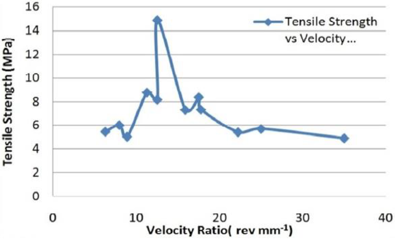
Effect of velocity ratio on tensile strength. 87 Reprinted by permission from Elseveir, 2018.
Microhardness
Hardness of the stir zone is always lower compared to the base material. It is because of the thermal degradation of the polymer associated with mechanical stirring action of tool. Hardness of the weld joint is affected by the tool rotating speed and high heat input, with higher tool rotational speed and temperature. Vickers microhardness tests conducted on the AA5059/HDPE dissimilar joint were conducted by Khodabakhshi et al., 69 Improvement in hardness is attained by moving from one side of HDPE (4.6 HV) to the other side of AA5059 (86.7 HV). Shahmiri et al. 88 reported that increase in rotational speed and heat input will have on significant effect in the hardness of the joint. This is due to the presence of aluminium chips in the re-solidified polymer at the weld nugget. Huang et al. 47 performed FSW to join the aluminum alloy 2060 to carbon fiber Poly ether ether ketone Figure 3 showcase the hardness variations of welded joints with respect to rotational speeds. It clearly shows that the increase in rotational speed will decrease the hardness value of Al anchor. Huang et al. 84 made a similar finding when they looked at the microhardness of welds in various regions. Microhardness values were found to have an irregular distribution on the dissimilar FSW of AA6061-T6 and PEEK combination. The average value of microhardness of stir zone is more than that of the polymer basemetal but less than that of aluminum alloy 6061 T6. A hardness value of 15.2 HV was achieved in the stir zone, where high hardness was found in the aluminium basemetal; the low hardness value on the polymer side was mostly owing to plastic deformation and high heat input produced by the rotating tool. 84 Figure 4 shows the Load depth curves of Vickers hardness indentation for the joint aluminum alloy 5059 to High density polyethylene. Reduction in hardness by thermal degradation. Khodabakhshi et al. 69 investigated the hardness gradually reduces in HAZ & TMAZ due the softening of material and recrystallization. Derazkola et al. 89 investigated hardness of welded dissimilar joints with and without alumina nano particles the average value obtained at the joints 71 and 79 shoreD for FSW and FFSW respectively. Results indicated the decrease in hardness of PMMA leads to the thermal degradation and some change in molecular weight of the polymer, by inducing nano particles hardness increased as expected. Figure 5 indicates the microhardness distribution of friction based filling stack joining for aluminum alloy 6082 T6 to Polypropylene the above Figure 5, clearly shows uneven microhardness distribution on the weld surface. Rout et al. 71 carried out hardness test on the welding of aluminum alloy with polypropylene and resulted that low hardness of the joint as 20HV. Huang et al. 90 PTMAZ is most heat affected region by the process where low microhardness observed.
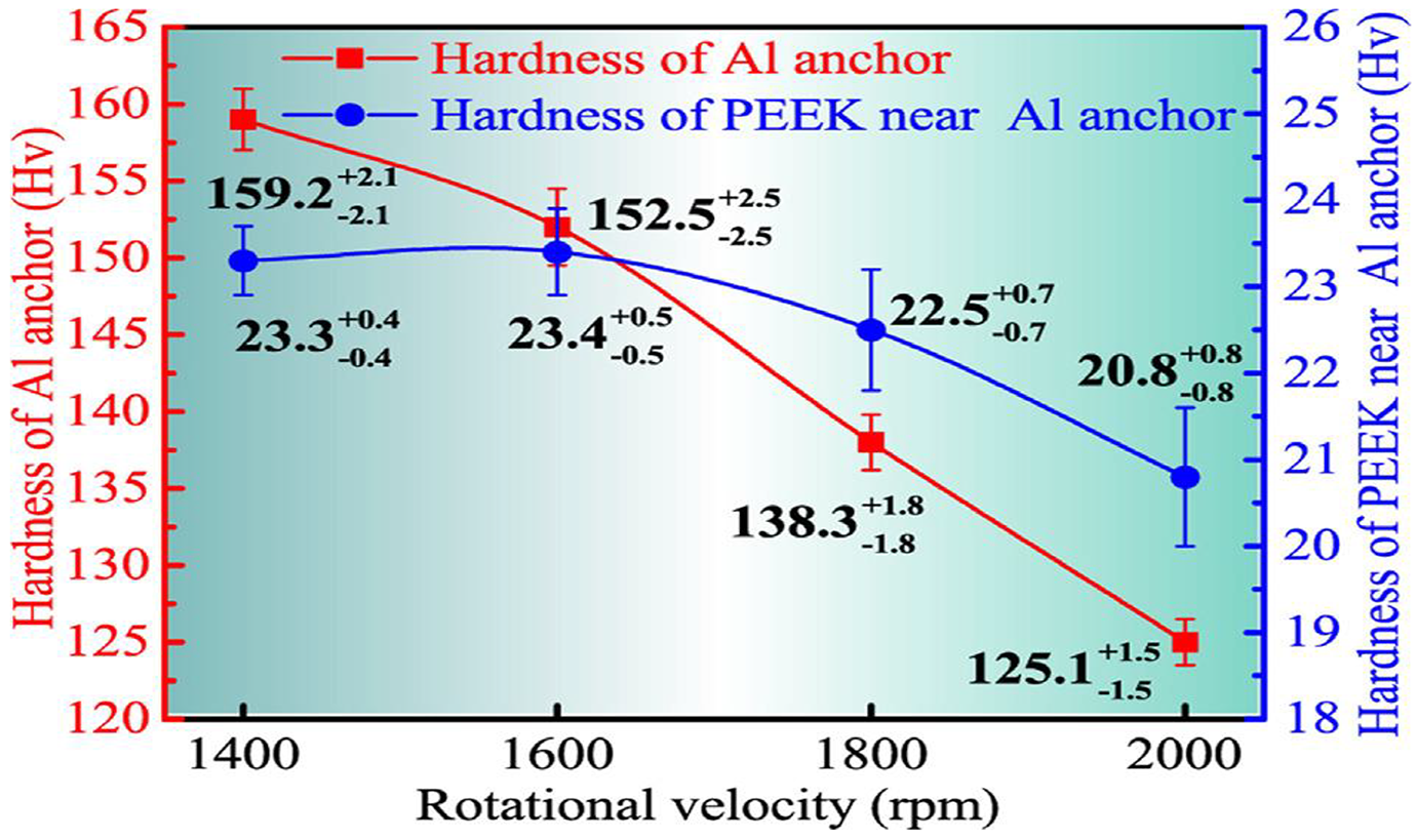
Hardness of the typical locations for the Al anchor and its surrounding PEEK. 47 Reprinted by permission from Elseveir, 2018.
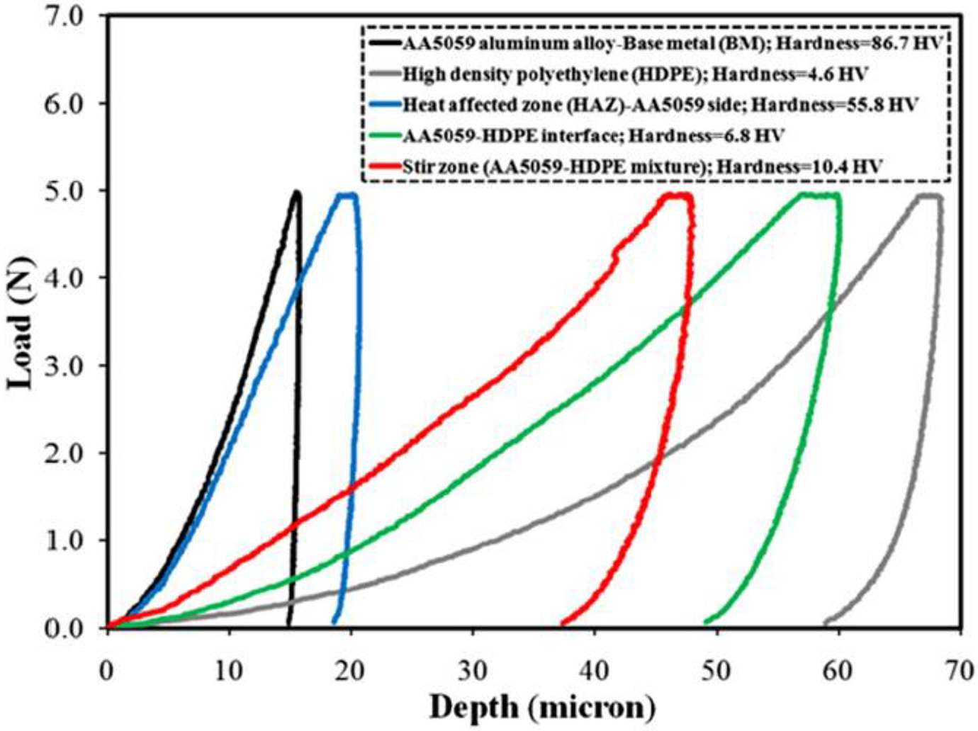
Indentation hardness load–depth graphs for BMs AA5059, HDPE, HAZ and SZ. 69 Reprinted by permission from Elseveir, 2014.
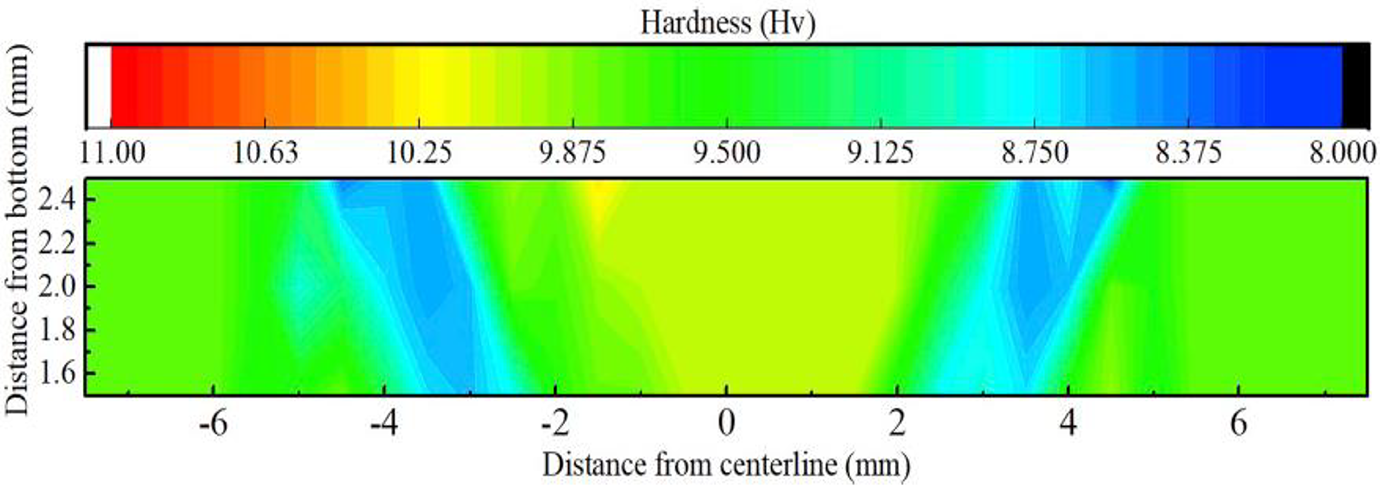
Microhardness distribution of FFSJ joint. 90 Reprinted by permission from Elseveir, 2019.
Microstructural characterization
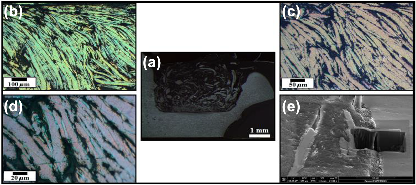
Khodabakhshi et al. 49 used the FSW approach to examine the bonding process and interface characterization of dissimilar AA5059 and HDPE. Figure 6(a) indicates microstructure characterization analysis from aluminum alloy 5059 base alloy, the presence of rod shaped smaller impurities with diameter 77 nm and length 250 nm which are found in Al-Mg alloys. Due to the stirring of FSW tool the initial coarse grain structure was broken down into an average coarse grain structure of 100 nm. The presence of HDPE polymer in joint influence the grain structure of aluminum alloy. Some voids formed on the joint interface is controlled by the heat input. Rahmat et al. 91 investigated dissimilar weld on aluminum alloy 7075 and polycarbonate, Figure 7 shows the SEM microstructures of dissimilar weld. The aluminum dislocation is shown in Figure 7(a) and is interlocked into the polymer side. This is due to the fact that when harder material is put on the advancing side, it quickly transports into softer material. Some voids can be seen around the stir zone in Figure 7(b) and (c). It’s due to a lack of plunge depth, a faster welding speed, and inadequate forging pressure. Since it is a mechanical interlocking, there is no intermetallic compound coating formed between the joints. Shahmiri et al. 88 Figure 8(a) and (b) shows the presence of cold rolled grain the base aluminum which is deformed in the direction of stirring of tool. In stir zone the cold rolled grains transformed into fine equiaxed grains because of recrystallization shown in Figure 8(c) fragments of aluminum were found in the nugget of SZ shown in Figure 8(d) subjected to high strains before being cut out of base aluminium. Presence of oxygen is the reason for thermal degradation on the polymer side. The space between the aluminium nugget and the polymer will widen as the temperature rises. This gap is formed due to the cooling of joint after welding which have a large difference between thermal expansion coefficient of polymer and metal. Similarly, Huang et al. 84 investigated friction stir welding on dissimilar materials Figure 9 depicts the macrostructure of dissimilar materials welded at different welding speeds. Al anchor is formed by the action of rotating tool, size of the Al anchor in retreating side is comparatively smaller than advancing side due to the higher peak temperature in the advancing side. A surface groove is shown in Figure 9(a) due to low welding speed, which results in melting and overflowing of molten polymer at high welding heat input, resulting in inadequate filling of materials. Length and the thickness of the Aluminum anchor is decreased with the increase in welding speed.
(a) Macro image of cross section. (b–d) Microstructure of dissimilar welding. 49 Reprinted of Informa UK Limited, trading as Taylor & Francis Group, 2017.
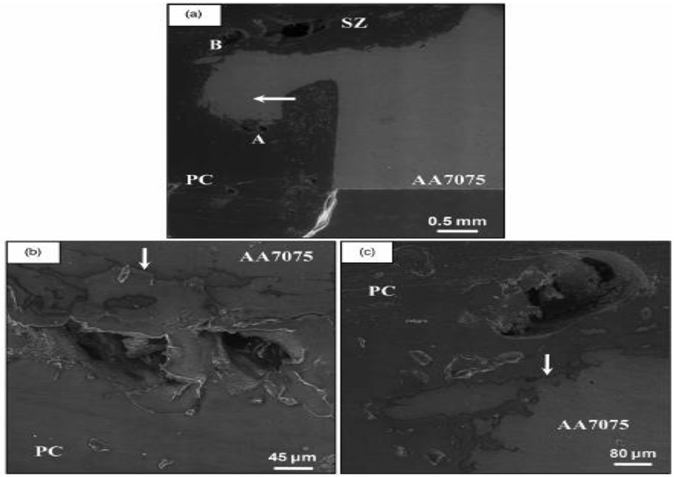
SEM microstructures of dissimilar welded AA7075 to Polycarbonate. 91 Reprinted of Informa UK Limited, trading as Taylor & Francis Group, 2014.
Microstructure for different region 5052 and polymer. 88 Reprinted of Informa UK Limited, trading as Taylor & Francis Group, 2017.
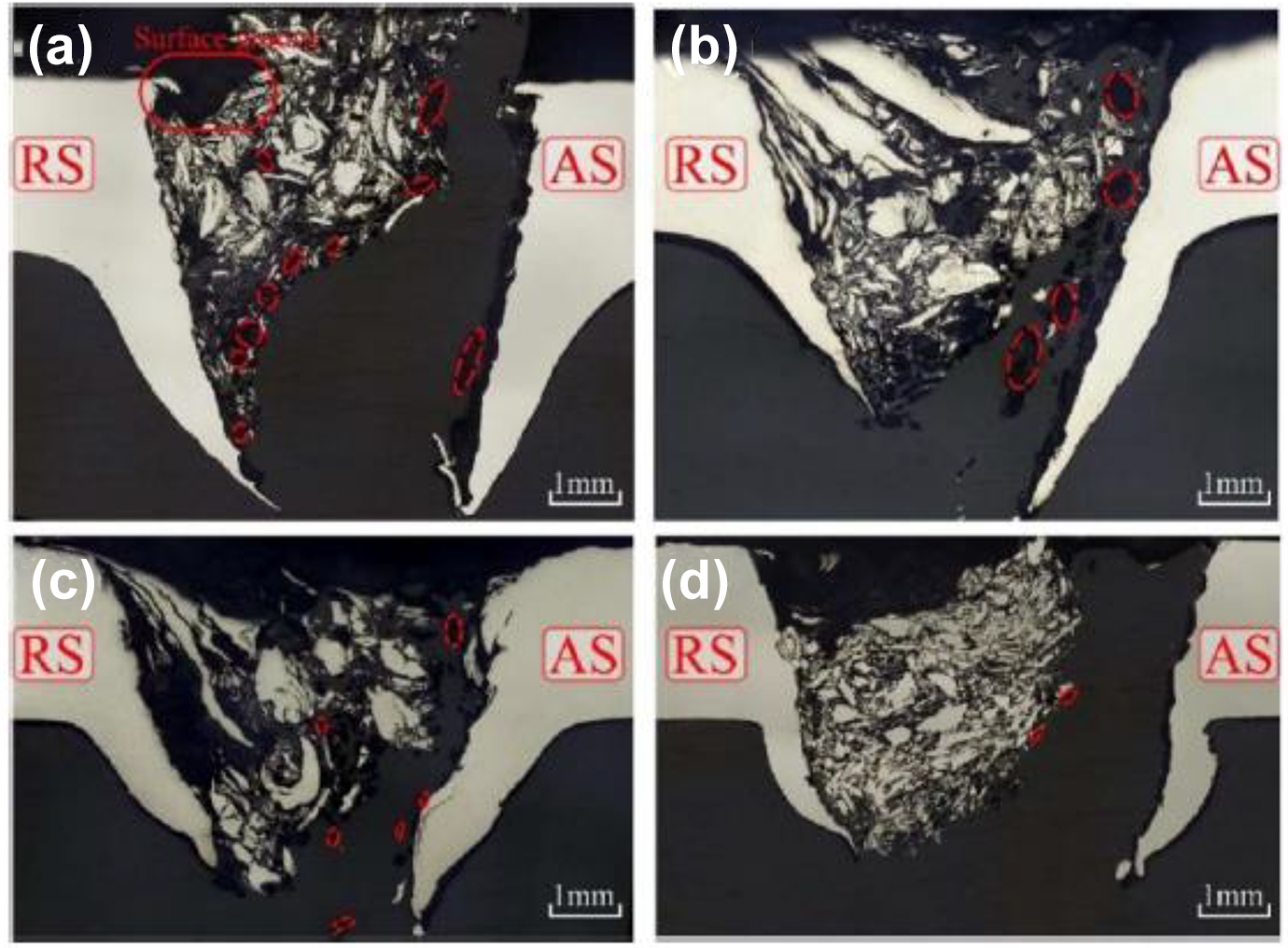
Macrostructure of dissimilar weld of 6061 PEEK for different welding speeds (a) 30 mm/min, (b) 50 mm/min, (c) 70 mm/min, (d) 90 mm/min. 84 Reprinted of Informa UK Limited, trading as Taylor & Francis Group, 2018.
Defects in friction stir welding
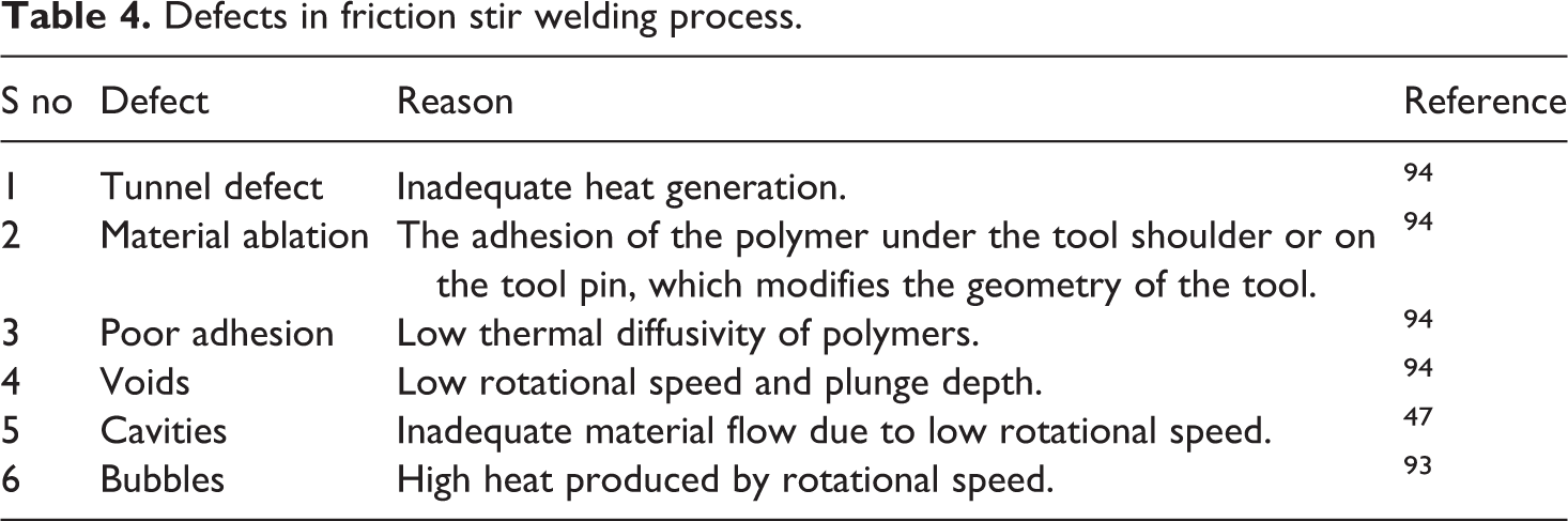
Figure 10 depicts the cavity defect produced between the polymer and the metal as a result of rotating speed. Low rotational speed generates less frictional heat, resulting in insufficient material transfer and cavity defect under the stir zone. The heat input increases the flow of plasticized material, which removes the cavity defect as the tool rotational speed increases. Figure 11 shows the warppage and deformation in upper Al sheet due to rotational speeds that is because of minimal thermal conductivity of carbon reinforced polymer and the heat generated in the tool and workpiece is trapped and distorts the aluminum sheet. 92 Table 4 depicts some of FSW flaws.47,93,94
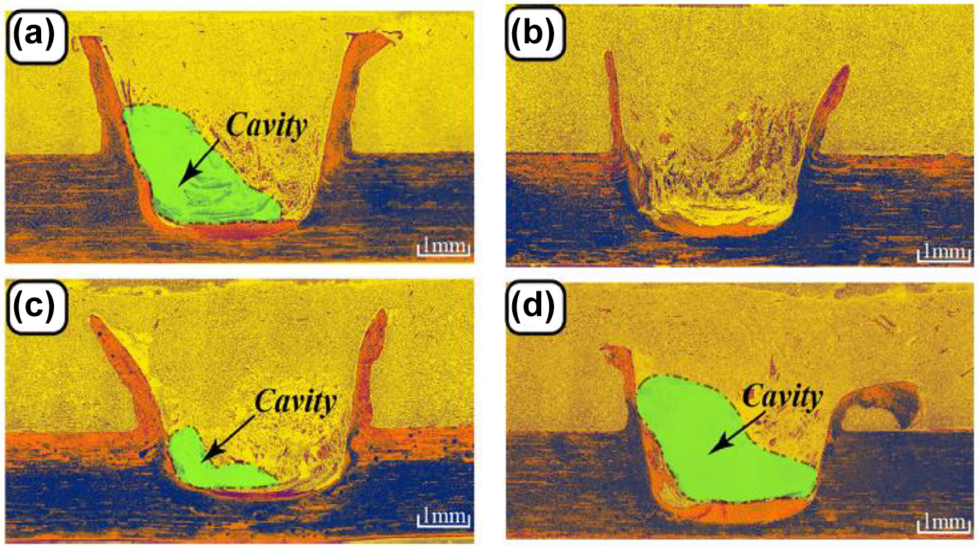
Macrostructures of typical joints at different rotational speeds: (a) 1400 rpm, (b) 1600 rpm, (c) 1800 rpm and (d) 2000 rpm. (The yellow colour represents SCF/PEEK; the green colour represents the defect; the orange means the AA2060-T8.) 47 Reprinted by permission from Elsevier, 2018.
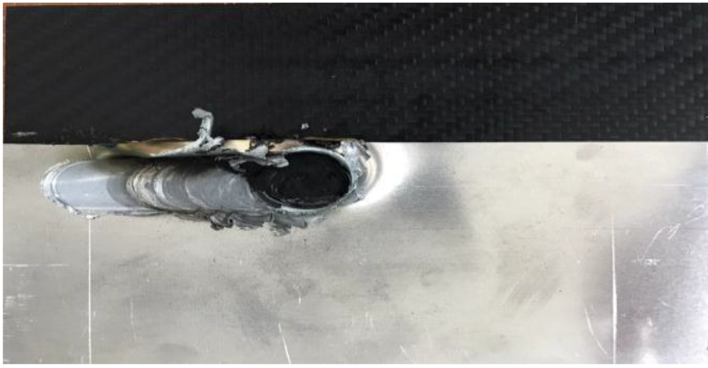
warppage in Aluminum sheet due to rotational speed. 92
Defects in friction stir welding process.
Inherent issues of FSW in joining metal to polymer
In FSW process material flow reversal in advancing side causes formation of stagnant zone near to the tool. It resulted in wormhole defects due to inadequate material flow in advancing side. 95 During dissimilar FSW process, placement of material plays a major role, whereas aluminum placed on the advancing side and polymer material placed on the retreating side, since the advancing side experiences more heat compared to the retreating side. 95
Major issues of dissimilar welding is the difference in the melting point, where polymer reaches its melting point soon compared with metals, polymer will easily degrade with high heat, and it deteriorate the properties of the weld joint.73,75,96
Recent advancements in friction stir welding process
Stationary shoulder friction stir processing
Friction stir processing (FSP) is a promptly emerging solid state technique for production of surface composites. Most composite fabrication techniques, such as powder metallurgy, injection moulding, diffusion bonding, laser technique, were done in the liquid phase at elevated temperatures, resulting in the formation of intermetallic compounds and undesirable phase change between the reinforcement and parent material. To overcome the above issue fabrication of composite should be conducted at low melting points which FSP could offer. 97 FSP is used to improve base material characteristics such as surface properties, grain structure refinement, and the material’s ability to attain maximum ductility. 98 FSP process uses unique non consumable tool with modified shoulder and pin.99,100 As the tool rotates and approaches forward, the frictional heat generated at the interface of rotating tool pin and the parent material which directly results in the mixing of reinforcements and softening and plasticization of the parent materials, hence the processed region obtained. As reported the stationary shoulder tool produces low heat input and grain refinement in stir zone which results in fine equiaxed grain microstructure in stirzone, 101 since stir zone of the weld undergone dynamic recrystallization. This process reduces flaws like weld thining, 102 voids and cavitation due to the improper material flow.103,104 During conventional FSW process tool plays a major role in heat generation during welding, but in the case of dissimilar materials will behave in a different way because of their diverse properties. So development of a specific tool to address this issue. So far the effective tool for welding polymers was developed by Strand, 105 main advantages of this stationary tool is that it able to hold the molten material inside the weld zone and also improves the surface quality. 55 Patel et al, 106 proposed a novel stationary shoulder friction stir processing technique with low heat input grain refinement, tool consists of a nonrotating shoulder and rotating pin. This tool reduce the temperature around welding zone and also increase grain refinement throughout the weld zone area. 107 as reported, by using external stationary tool the arc corrugation and flashes of the weld are low compared with conventional method this is because of stationary shoulder which prevents the material from flowing out of the weld area. This process encourages more material flow into the weld region which shield against the formation of cavity and tunnel defects in weld joints. Thus the external stationary shoulder is the improved version of solid state traditional process. 108
Friction stir scribe technology
Friction stir scribe (FSS) technology is a novel technology of FSW that aids in the joining of incompatible base materials with varying melting points.109,110 Defects like voids and flashes in the weld bead due to the difference in temperature of dissimilar materials will lead to deterioration of weld and poor bonding strength. 111 To overcome the above difficulties FSS process is used, it consists of a cutter scribe at the tip of the tool pin which reduces the heat generation while welding. During the lap welding process the tool pin interacts with the upper plate and cutter scribe only approaches the bottom plate. 112 As the tool pin rotates and moves forward cutter scribe creates a rivet like mechanical interlock bonding mechanism. Maintaining clearance between tool and bottom plate ensures that this process prevents the material deformation in the bottom sheet. 113 Figure 12 shows the scribe tool tip design and working mechanism of the weld.
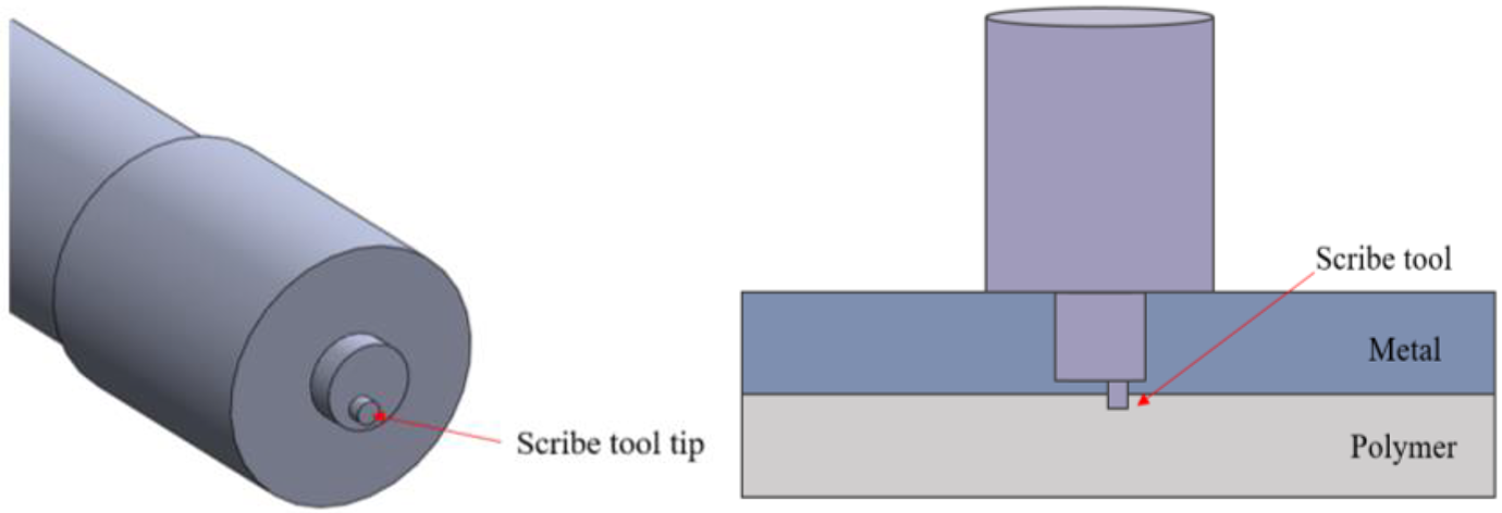
Scribe tool tip and schematic representation of mechanism.
Friction stir spot joining
Bonding mechanism
Friction stir spot joining (FSSJ) is the most attractive solid-state welding for producing good quality welds. Technology of “friction stir spot joining” is primarily used to connect metal structures. The joints were created by a stirring tool made up of high hardened steel connected to a friction stir machine that applied pressure to the tool material and welded samples during the welding process. Tool pin and shoulder is always in contact with the surface metal part during welding process. During the welding process, the tool rotates and plunges into the surface of the base materials, generating heat; at this point, the softened base material behind the pin fills the gap produced by the pin, which forms the joint between base materials. Micro mechanical interlocking and adhesion bonding between the base materials are the bonding mechanism in FSSW technique.114–118 The primary benefit of friction stir spot joining is that it is simple to join and does not require surface preparation or predrilling holes, No hazardous gases generated during the welding process, and joints are readily fixed.
Effect of FSSJ process parameters
The input parameters of welding process like dwell time, tool rotational speed and plunge depth decides the properties of weld joint. The shape, size and mechanical properties of the weld joint are depending upon the input process parameters. 119 Dwell times plays crucial role in joint strength, with longer dwell times in friction stir spot welding resulting in greater maximum load to fracture values. 120 A Friction stir spot welding of AZ31B with nano-SiC particles where higher dwell times produce finer reinforcement distribution at weld stir zone. Grain size of reinforcement in weld nugget increase with increase in heat treatment. This is because the high energy stored in the stir zone of the welded joints allows the grain growth. In this study the improvement of strength is attributed with the fine grain size. 121 Song et al. 122 investigated the influence of plunge speed on friction spot welding of AA6061-T6 sheets, 2,4,6,8 and 10 mm/min are the range of selected plunge speed. Results clearly shows that tensile shear load increases upto 6mm/min and remains constant. Shen et al. 123 investigated the influence of tool rotation speed and duration time on 6061-T6 sheet with rotational speed ranging from 1200, 1500, 1800 and 2100 rpm and duration time from 2, 3 and 4 seconds. The higher tensile result 2107 N got at rotational speed of 2100 rpm and 4 second duration time.
Tensile strength
The rotational speed has the greatest influence on weld joint lap shear strength, followed by weld time, plunge depth, and force.124,125 Increased rotational speed enhances lap shear strength by generating adequate heat input and a larger joining area. 48 The weld joining area increases by 70% when the rotational speed is increased from 1900 to 2900 rpm. The greater the joining area, the closer the carbon fibres and PPS matrices with aluminium are in contact. Plunge depth is vital in macro mechanical interlocking because it regulates the development of metallic nubs at the interface of metal and composite, which can improve adhesion. Therefore the larger heat inputs results in stronger joints sometimes it leads to rupture in weld zone area. 125 Furthermore, maximum tensile shear force and friction displacement stir spot joining with diverse interlayer thickness films and joints without interlayer films. 126 Goushegir et al. 114 stated that the weld zone is divided into three distinct regions: the adhesion region, the transition region, and the plastically deformed region in the centre. Cracks begin at the outermost edge of the adhesion zone and propagates along the interface region between the aluminium or polymer and this layer in a plane parallel to the applied load path, causing the joints to fail. 48 This crack propagation is reason for cohesive failure in a plastically deformed zone, where greater number of carbon fibres and polymer matrices remain attached to the aluminium surface. 114 Flow of the liquefied polymer in the bonding area is facilitated by a higher rotational speed and a longer joining dwell time. Higher plunge depth is required in shorter joining time to facilitate the material flow. 124 Figure 13 shows that the plasma electrolytic oxidation (PEO) coating joints shows good results than the specimens prepared without PEO treated. PEO treated specimens enhance the joint strength and failure occurs 1228 N where failure load of specimens without PEO observed 306 N that is three times lesser than the previous one. 127 Tensile strength increases with the increase in tool rotational speed up to certain value and then decreases regardless of speed where maximum tensile shear strength of aluminum alloy 5052 and CFRTP obtained at speed of 1600 mm/min− 1 is 2.9 kN shown in Figure 14. 6 In similar study AA2219/PP-C30 S joints were made and got shear tensile force of joints increases from 268 N to 540 N with the increase in tool rotational speed from 600 rpm to 1800 rpm. 128 Figure 15(a) shows the load extension curve of the lap shear tests of samples in sandblasting condition. Where anodizing condition Figure 15(b) produces stronger joints than sandblasted condition. 1792 kN is the average strength of the joints obtained at anodizing condition, compared with 292 kN obtained in sandblasted alloy. 115 These results clearly show that the rotational speed, plunge depth & stirring duration plays a major role tensile strength of welded joints.
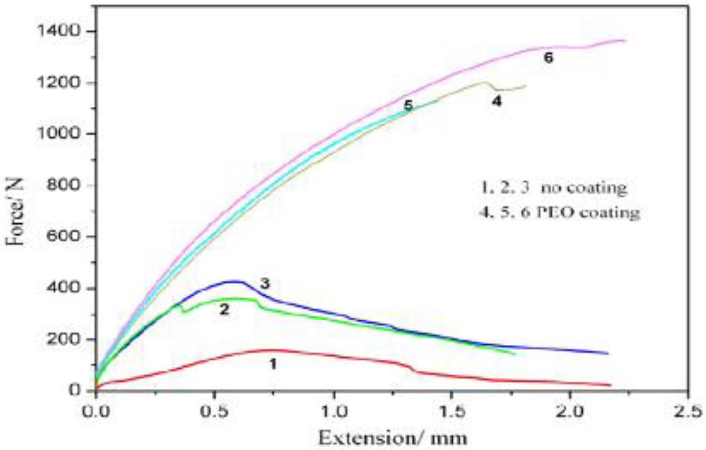
Lap shear strength of AA5052 and Polypropylene with and without PEO Coating. 127 Reprinted by permission from Elsevier, 2017.
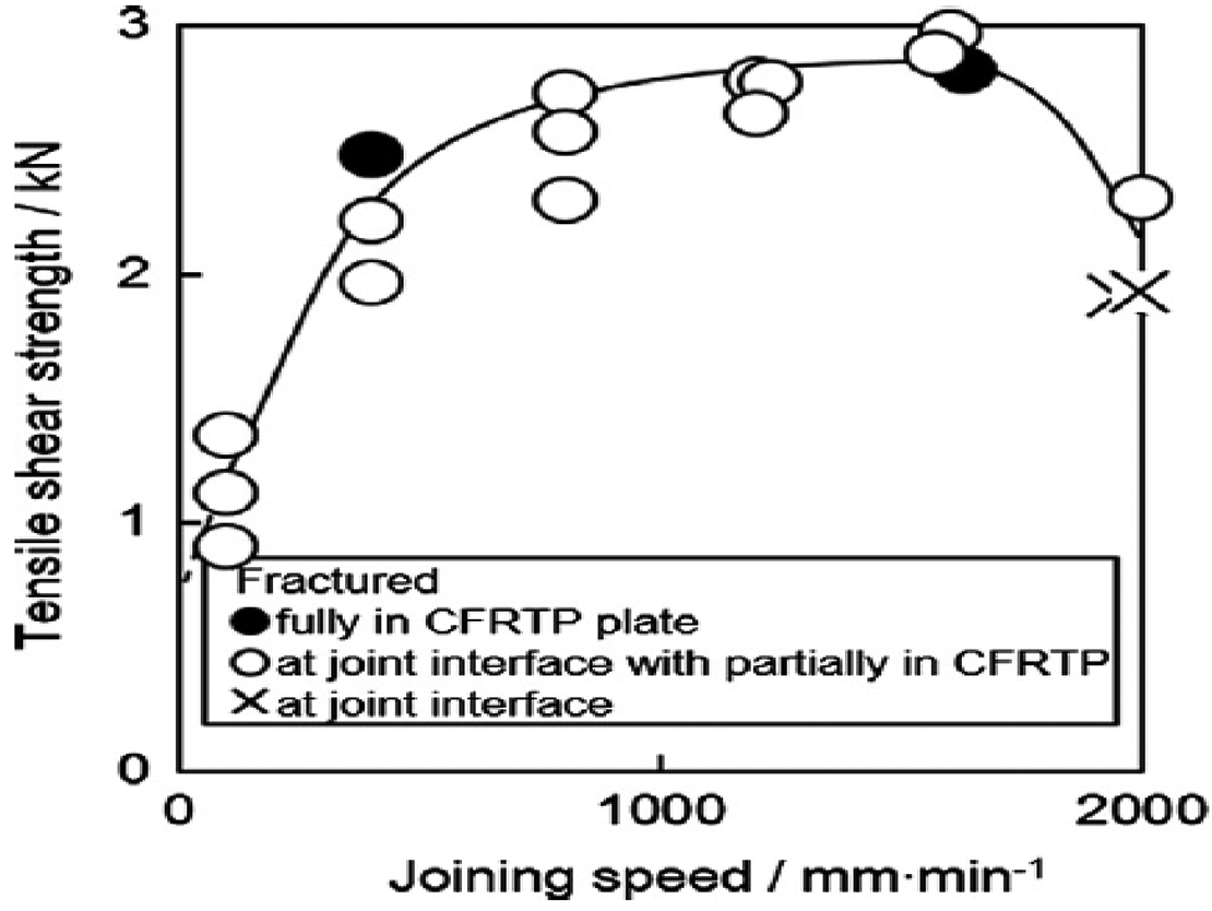
Relationship between Tensile shear strength vs Joining. 6 Reprinted by permission from Elsevier, 2015.
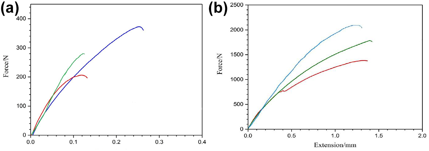
Force Extension curves of Dissimilar AA5052 alloy and Polypropylene (a) sand blasted condition (b) anodizing condition. 115 Reprinted by permission from Elsevier, 2019.
Microstructural analysis
Linear intercept method is used to measure the average grain size. Fine sized grains in stir zone were obtained by the recrystallization happened during stirring process. Finer grains results in higher hardness in stir zone of the welded joint. The dynamic recrystallization of material occurs when the crystalline materials are broken at elevated temperature, where new sub-grains and regular boundaries formed with the continuous annihilation of dislocations. 129 Rotational speed encourages the grain growth at minimum temperature. 130 Zhang et al. 131 reported that heat input is an important factor which decides the size of the grains in stir zone, coarser microstructure was obtained by higher peak temperature at higher rotational speed about 1541 rpm. Figure 16 reveals the microscopic and macroscopic structure of a friction spot welded aluminum alloy AA5052-H112 at rotational speed 1541 rpm and 5 seconds dwell time. Figure 16(a) shows macroscopic cross section of FSSW joint. Figure 16(b) exhibits elongated grains by work hardening. TMAZ is differentiated by deformed grains compared to BM and HAZ. Stir zone consists of equiaxed and refined grains. Compact structures observed in Stir zone and Heat affected zone because of the stir action by tool pin. 131 In similar study effects of parameters like rotational speed, plunge depth and dwell time on shear tensile failure, hook formation and heat input energy, defect free joint obtained at rotational speed 1200 rpm and dwell time 2 seconds with few minor cracks found in hook region due to low heat input energy. 132 Figure 17 shows the SEM images of fracture surface of dissimilar joints AA5052 with polypropylene in which gas bubbles formed due to the thermal degradation of polymer, which produce hydrogen, aliphatic and unsaturated hydrocarbons increases with temperature. 117 Bubbles formation causes a non-uniform shear stress in dissimilar joint. Shear stress increased in adjacent areas due to shielding stress created by bubbles. With the increase in plunge speed, size of grains in SZ increases since the temperature at higher plunge speed is more and grain growth occurs. The grain size, however, increases with the tool rotational speed due to plastic deformation. 133 Larger grains in SZ is observed due to the larger static grain growth during high plunge speed. 116
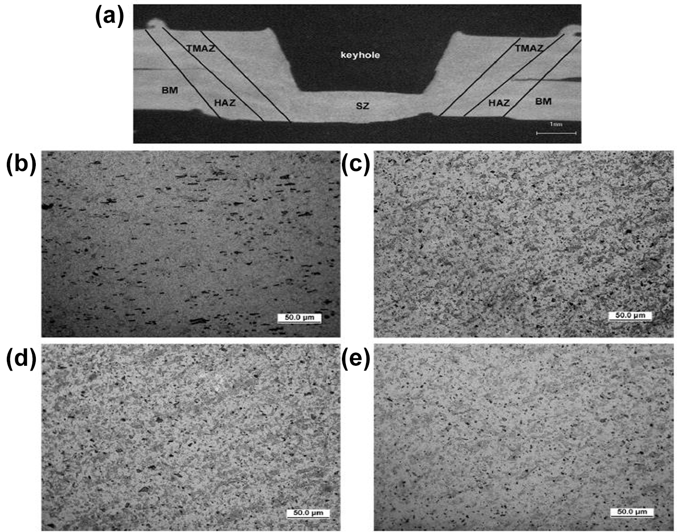
The microstructure of a weld joint at rotational speed of 1541rpm and dwell time 5 seconds. (a) Macro image of joints, (b) base material, (c) heat affected zone, (d) thermo mechanical affected zone and (e) stir zone. 131 Reprinted by permission from Elsevier, 2011.
SEM images of Fracture surface as AA5052/PP joints (a) alloy side and (b, c) polymer side. 117 Reprinted by permission from Elsevier, 2019.
Defects in FSSW
Several types of weld flaws were formed during FSSW process. Low heat generation and inadequate material flow cause defects such as lack of bonding, voids, fractures, and a deficient bonded region. These flaws are linked to the material flow and processing parameters. 134 Formation of hook in the material is associated with the tool rotational speed which leads to improper flow of base materials and lack of pressure. 135 F Yusof et al., reported formation of air bubbles between the Aluminum alloy and PET polymer. The majority of the bubbles were found in the tool region at the centre of joined area. Reason for bubble formation is high heat temperature produced by tool rotation. Plunge depth mainly influences the size of the bubble at lower plunge depth the size of the bubble is smaller. Bubble nucleation may lead to shear failure load of the joints. 136 Size of voids increases with increase in rotational speed at given time. Hence the weld duration plays a major role in increasing materials fluidity. 137 Main disadvantages in the FSSW is the keyhole formation due to the tool. The presence of keyhole is a barrier to achieve high strength welds in FSSW process. 138 To avoid this keyhole defect refill FSSW method proposed by Helmholtz. 139 were it is used to fill the key hole left behind the tool with special tool. Tool material should be cooled down to room temperature at the beginning of every experiment to avoid pull-out of material from weld nugget. The explanation for the pull-out is due to excessive heat output during the previous weld and inadequate cooling of the material. 140
Laser assisted joining
Laser joining of polymer and metal uses a laser source as the medium; it is a non-contact welding method that achieves deep penetration through the use of a heat source. 141 Higher penetration depth and less heat affected zone area obtained in this laser welding process. 142 Despite laser joining is advantageous for the manufacturing of hybrid and micro complex components, surface pre-treatment is necessary for clean and faster welding. 143 Laser welding consists of two types of joining process (i) Deep penetration welding or keyhole welding (ii) Laser beam conduction. With higher intensities of laser produces high penetration depth and minimum heat affected zone. There are some challenges in welding reflective materials like aluminum by using laser for welding aluminum. It is recommended to use conduction mode of laser where penetration is more stable and shallow. 144 The laser mechanism is depicted in Figure 18. 145
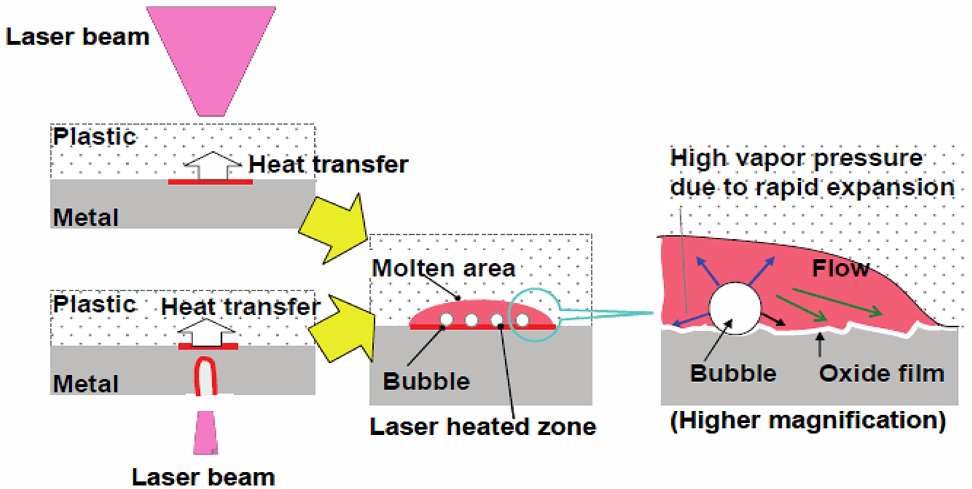
Mechanisms of laser direct joining between metal and plastic. 145 Reprinted by permission from Elsevier, 2012.
Bonding mechanism
Bonding of dissimilar metal to polymer is complex due to their interfacial as reported, polymer having low wettability compared with metals, it is because of lower surface tension of polymers. 146 The development of laser welding is the Laser assisted metal and plastic (LAMP) technique. Weld joint is formed due to the melting of base materials by the rapid heat produced by laser. This heat promotes reaction in the interfacial area and aids in the attachment of polymer to metal via an oxide layer that covers the whole metal surface. 145 Lower melting temperature of polymer around 250°C starts melting compared to aluminum alloy which is around 550°C. 147 As a result, polymer material will easily decompose at a temperature below 400°C. This indicates the importance of heat input in mechanism during joining process. So, the heat input is the major concern in this type of joining. 148 A unique heating mechanism of LAMP technique used to control the temperature in interfacial region has advantages than other conventional process, where joining is characterized by the formation of bubbles between plastic and metal surface. 146
Tensile strength
Jung et al. 149 conducted experiment on LAMP joint of AA5052 aluminum alloy and PAN type made of Polyamide6 and 20% chopped carbon fiber. The joint strength is increased with the increase in travelling speed and laser power by 3mm/s and 1000 W upto a limit and decreases with the further improvement in laser power 1200 W by thermal degradation due to excessive heat input. Lamberti et al. 147 welded 0.5 mm thick aluminum and 1 mm thick Polyamide overlap configuration. Figure 19 shows the chart between shear load and power, maximum shear load obtained 1600 N at modulated power 300 W, for higher heat energy input the shear load was decreased and some bubbles were found at the interface. In the Figure 20, Li et al. 150 showed relation between tensile lap shear force and the surface structures, the tensile strength decrease with the increase surface roughness and stated that the bonding strength of the joint is depend upon density and distribution of features. Consequently Kajihara et al. 26 investigated aluminum alloy 5052 and polyethylene terephthalate with alumina particles blasted to improve joint strength. Figure 21 shows the shear strength at different polymer temperature where temperature of polymer plays a major a role in shear strength of the weld joint. Low shear strength obtained in low temperature because of insufficient heat which make less fluidity of polymer. Lower strength noted at 280°C due to thermal degradation of polymer at high heat production. Zhou Zhang investigated laser welding on AA 7050 and CFRP Polyamide6 with lap welding configuration with AA 7050 plate of thickness 2 mm and CFRP of 3.5 mm where aluminum plate placed on the upper side. 151 Figure 22 clearly shows that the influence of heat input over shear strength where shear strength increases with the increase in heat input after certain limit it starts decreases because of thermal degradation of polymer. Due to the minimal heat input the insufficient melting of polymer affect the bonding strength of the joint. 151
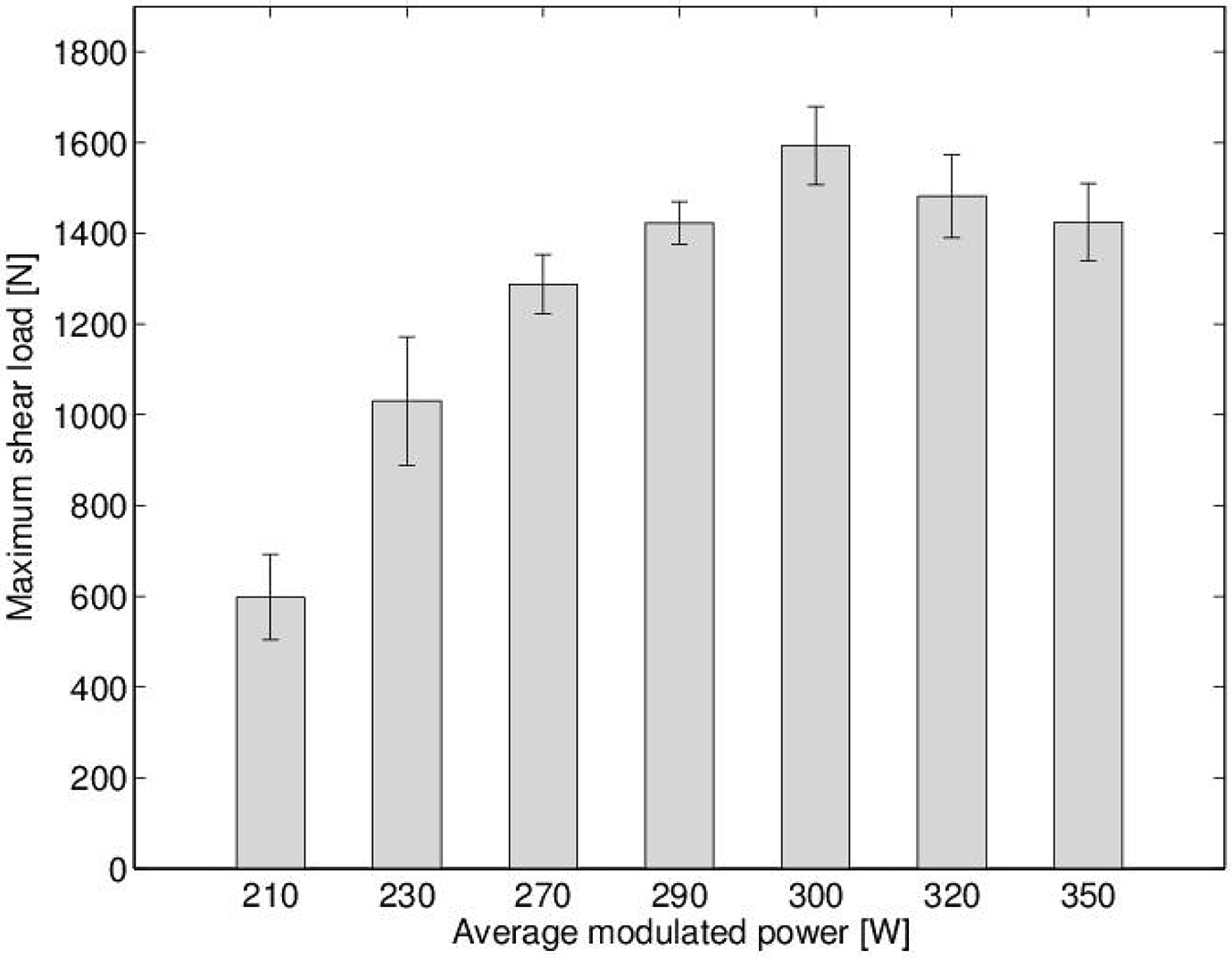
Maximum shear load (N) vs modulated power (W). 147 Reprinted by permission from Elsevier, 2014.
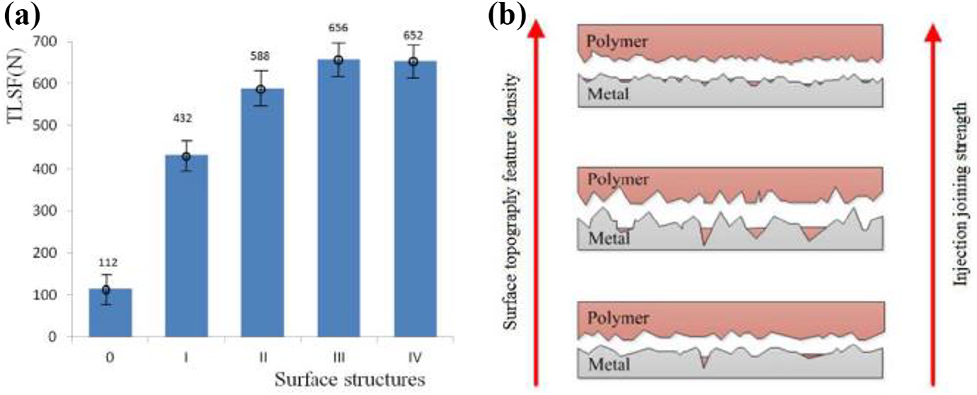
(a) Relation between Tensile lap shear force and surface structures. (b) Fracture at interface. 150 Reprinted by permission from Elsevier, 2018.
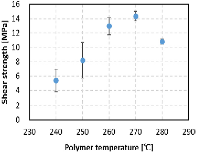
Shear strength for different temperatures. 26 Reprinted by permission from Elsevier, 2018.
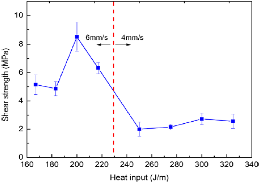
Shear strength vs heat input. 151 Reprinted by permission from Springer nature, 2017.
Microstructural characterization
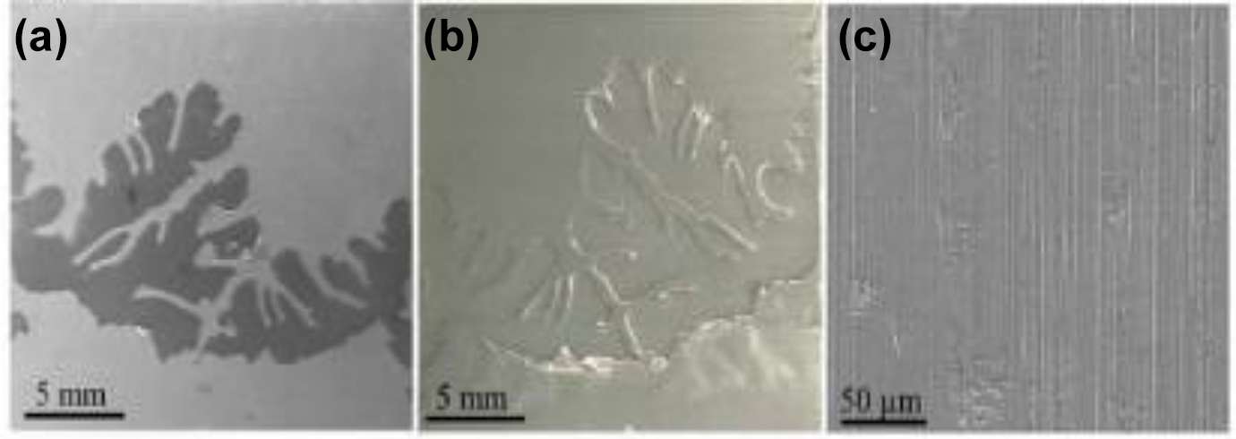
Microstructure analysis in Figure 23 clearly shows the boundary between HAZ and the base metal. The heat generated by laser energy is radiated on the aluminum alloy. Heat affect zone produced during the welding process is less. The grain structure in the HAZ is smaller compared to the base material. 152 Eventually, Huang et al. 153 produced dissimilar welding on steel and Polymethyl methacrylate (PMMA) by using Laser welding found weld strength is obtained with low laser power, Coincidentally a very low laser thermal heat input leads to lack of fusion. Some bubbles formed at the interface of the joint where PMMA decomposed, long pulse duration increase input thermal energy per unit area, the absorptivity of the laser beam is greater at this point, resulting in more polymer melting and wider beads. In similar study Tao et al. 142 joined TC4 alloy and Carbon reinforced Polyphenylene sulfide states that with increase in laser power, bubbles generated size is more at interface. Katayama et al. 154 welded 304 steel and Polyethylene terephthalate (PET) where Figure 24 SEM images shows some bubbles at the interface. TEM image shows the joint interface were tightly bonded on the atomic level. The base metal and the interaction layer identified by face centric cubic structure γ phase and Cr oxide film. 155
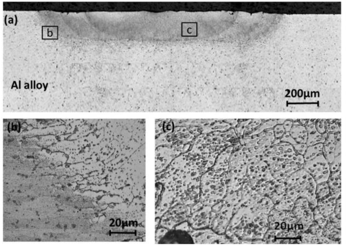
Heat Affected Zone in Al alloy. 152 Reprinted by permission from Elsevier, 2019.
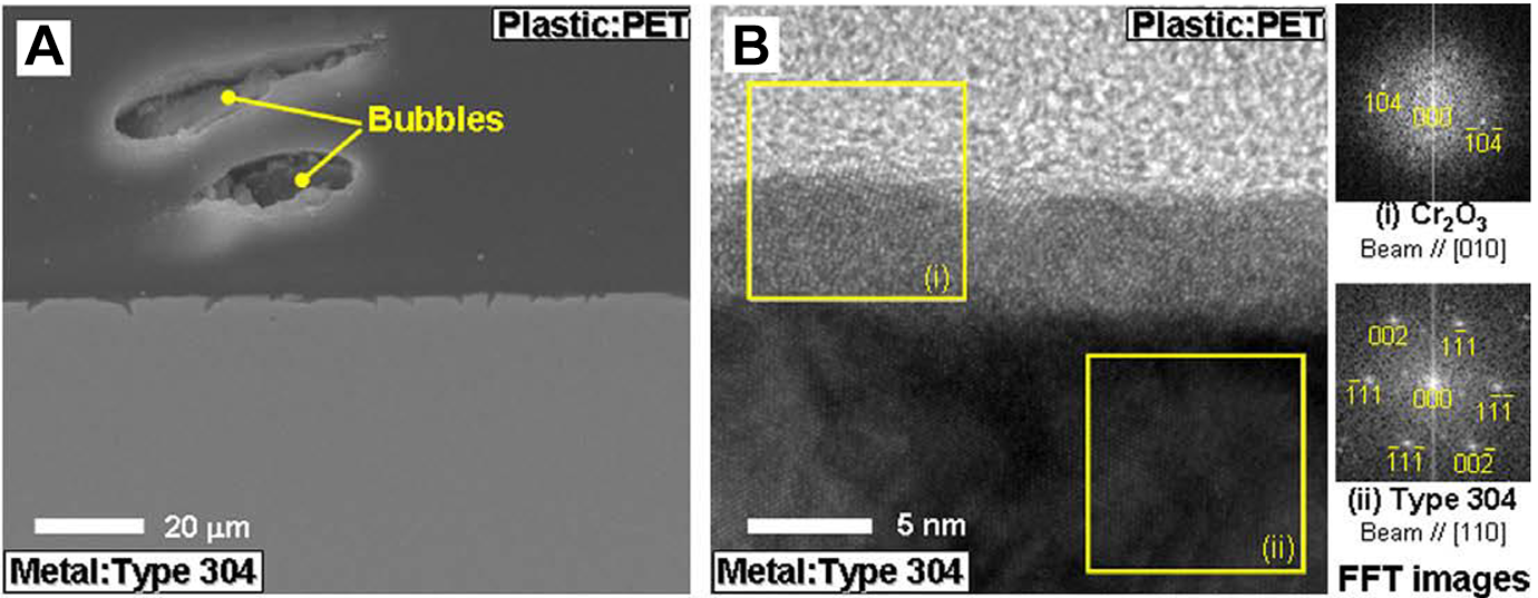
shows SEM (A) and TEM (B) image of PET and 304 steel joint. 155 Reprinted of Informa UK Limited, trading as Taylor & Francis Group, 2014.
Defects in laser assisted joining
Cracking is a major defect in laser welding due to high stress concentration, Gower et al. 33 investigated metal to polymer sandwich by pulsed laser welding and found some defects like porosity, cracks and undercuts in fusion zone. Overheating and decomposition of the material are caused by high heat input whereas low thermal heat input results in lack of fusion. 153 Excessive laser power could easily deteriorate the polymer, which results in less bonding strength for high load capacity applications. 143 Cracking occurs as a result of stress concentration during rapid heating and cooling. 33 High heat production makes the metal to melt and flow into the weld pool this may avoid crack formation in the weld. Since it is a rapid heating and cooling process, at high temperature porosity formed in the polymer area which leads to decomposition of materials so a controlled heat input should be maintained in this process. 156
Ultrasonic joining
Ultrasonic joining is a common joining technique for thermoplastic hybrid constructions. Mechanical vibrations with a higher frequency (20 to 40 kHz) and a lower amplitude (1 to 25 m) are employed to join thermoplastics. 157 Ultrasonic welding can be step up by sequential welding; for example, a continuous line of spot welding can achieve the same result as a continuous weld. 158 Viscoelastic friction and surface friction are the two primary heating mechanisms. 159 The cause for this ultrasonic joining mechanism is said to be interfacial friction between base materials. Whereas the viscoelastic heat effects when polymer’s glass transition temperature is reached, and it provides the maximum heat during joining. 160 Vibration and solidification are the two predominant stages of ultrasonic welding. Heat is produced during the vibration phases upon applying the ultrasonic vibrations and mechanical pressure, causing material to soften and flow. In the second stage i.e solidification stage where the matrix strengthen by the application of pressure and time. 161 With an increase in welding force, the material is fused by increasing the energy concentration at the interface of the joint. Sonotrode is used to apply mechanical vibration, welding pressure and solidification pressure to the specimen. Which is connected with transducer, this transducer generates mechanical vibration with the help of booster. The required amplification of the induced vibration is passed to the welding specimen through the booster. In ultrasonic welding process the mechanical vibration produces heat by increasing temperature in the interface area, material will refined with the help of pressure and heat. This process is the best suitable for thermoplastics whereas thermoset cannot be refined with application of heat and pressure. 162 as reported the mechanism of bonding is based on the intermolecular interactions between the surfaces. 163 There are numerous advantages to using ultrasonic welding. It is the fastest joining technique compared with other technique such as arc welding, resistance welding, and induction welding. It is also easily automated and thus used for mass production. 164 Minimal surface damage because low heat is generated at interface. 165 This technique can be used for spot and seam welding without the use of filler material 166 and does not produce any fumes or sparks. 167 Figure 25 portrays the principle of ultrasonic welding principle, 167 Ultrasonic welding eliminates common metallurgical defects like formation of brittle phases, porosities or intermetallic compounds as like fusion welding technique. 168 Some disadvantages include maximum seam size is not larger than 250 x 300 mm special tooling is required for complex shapes and it is costly. 4 It is limited to thin sheets around 3 mm thickness 167 because vibration can’t penetrate through thicker plates and produce good quality welds. 169 Mechanical vibration may produce noise from resonate state, the chances of specimens to fail in fatigue due to vibration cyclic loading. 165 Obaidi et al. 170 used ultrasonic welding to fabricate joints between AA6082 and ABS. Specimens were properly etched before joining. They investigated effect of aluminum plate thickness and amplitude of the vibration in strength of the joints. Results stated that it is important to prepare of aluminum surface before joining, they stated that without chemical etching no proper joining will obtained. Stronger joints obtained with the increase in amplitude of vibrations. Thickness of aluminum plate plays major role in joint strength. Yeh et al. 171 did joint of AA5052 and ABS polymer specimens. Results shows that the density of structure and the size of the contact area between metal and polymer influences shear strength of the joint. Maintaining mold temperature at 60°C has a positive impact on the shear strength. Staab et al. 172 produced different joints of AA2198 and AA5024 and thermoplastics like CF-PEEK and CF-PPS by using torsion ultrasonic welding technique. Heat treatment and welding time have a significant impact on joint strength. Wagner et al. 173 joined different grades of aluminum alloys AA2024 and AA5754 with SCF PA66. Surface pre-treatment for AA5754 sand blasted and chemical etching increased tensile shear strength up to 50 MPa.
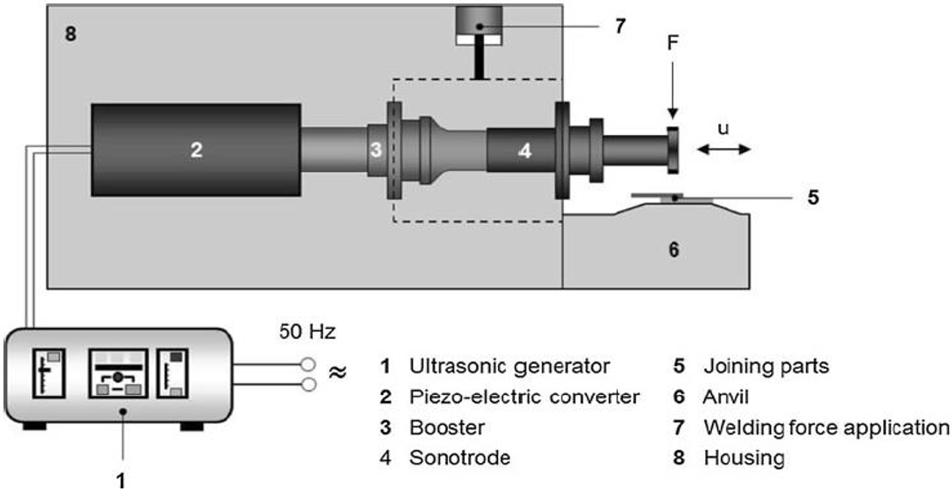
Principle of ultrasonic metal welding. 167 Reprinted by permission from Springer nature, 2012.
Induction welding
Induction welding is one of the fusion welding technique. It is mostly used to join electrically conductive materials. 174 This technique produce precise and accurate joining. The heat is generated within the electromagnetic field created by a high frequency eddy current and alternating current. Metal to polymer more accurately aluminum to polymer joints can also be produced by this technique. The aluminum side can be heated up and it conducts heat to polymer side. 175 It is possible to heat the polymer surface with the presence of carbon fiber in it. There is no additional filler material used during the joining process, and it is also a very inexpensive and fast welding technique when compared to others. Bonding mechanism describes the joining done by mechanical adhesion between polymer and metal surface, due to the piercing of polymer into the pores of the metal surface. Surface and interface energies plays a major role in wetting and compatibility of the weld joints. 176 The major disadvantages in this technique is only used for electrical conductive materials and surface preparation needed for better joint quality. 177 Weidmann et al. 178 used induction welding to create a hybrid joint of steel and Glass fiber/PA6. The investigators focused exclusively on temperature at the joining area and thickness changes. Results show that each surface pretreatment has different working temperature. There is no significant increase in bond strength with increasing thickness. Mitschang et al. 179 used an induction technique to create an aluminium and CF/PA66 joint and measured the effect of pretreatment methods and their results, as well as the effects of joining temperature and joining pressure. Surface preparation by corundum blasting and acidic pickling technique shows greater improvement in bond strength and also joining pressure plays a major role in bond strength. Adding interface layer of additional polymer sheets leads to higher bonding strength. The bonding strength is almost doubled when surface pretreatment and interface layer combined together. In other work, Didi et al. 180 produced AA5754 and PA66 specimens by using induction joining technique and explored the influence of different surface treatment and aging on the final strength of joints. Results clearly shows that the aging of aluminum before joining will reduce the shear strength of the welded joints. In another case after acidic etching its showing some improvement in strength.
Friction riveting
Friction riveting is a technique used to join dissimilar materials like metal and thermoplastics. 181 Friction riveting consists of metal anchor inside a polymer composite plate. Friction riveting 182 consist of three steps 1. Friction 2. Forging 3. Consolidation. Figure 26 shows the friction riveting process. The rotating rivet is moved towards base plate, where the rotational and axial pressure combined to cause friction and produce heat which melts the base metal and the tool tip is continuously fed into the base material. Due to the friction temperature increases rivet tip becomes plasticized and at this time the rotation decelerated and additional axial pressure is given on the rivet tip mushroom like structure is obtained. Last is the cooling stage where the rivet is strongly anchored inside the material. Friction riveting combines both mechanical fastening and friction welding hence there is no need of surface pretreatment and predrilled holes it will maximize production.183,184 Hence there are some limitations like only thermoplastics matrix only joined with this technique, as reported the joints undergo heat during friction and dwell times it may results in thermal degradation because of the polymer material’s low thermal conductivity. 185 Galvanic corrosion occurs while joining two different materials. 186 Amancio et al. 187 looked into the thermal degradation of polyetherimides during friction riveting process. Infrared thermography is used to evaluate the temperature during the joining. Heating rates and temperature are found to be increase with the rotational speed. Borba et al. 188 conducted similar research on thermal degradation of the glass fiber polyester during friction riveting, varying rotational speed and friction time to achieve better results. The temperature increase during joining was monitored using thermo camera on the polymer flash exerted from the polymer base material. The results show that increasing the rotational speed degrades the polymer and has a direct effect on the shear strength. Blaga et al. 183 studied the feasibility of friction riveting glass fiber reinforced polytherimide with metal layers. They maintained constant joining time, pressure and varied rotational speed. Got good results in rotational speed at 10000 rpm observed the formation of the anchor, with only few thermal flaws around the rivet is identified in optical microscope. Sequently Altmeyer et al. 182 investigated feasibility of joining Ti alloy/SCF PEEK achieved higher strength of 10.6kN at rotational speed 20000 rpm, welding speed 1.5 sec and friction pressure 0.8 MPa.
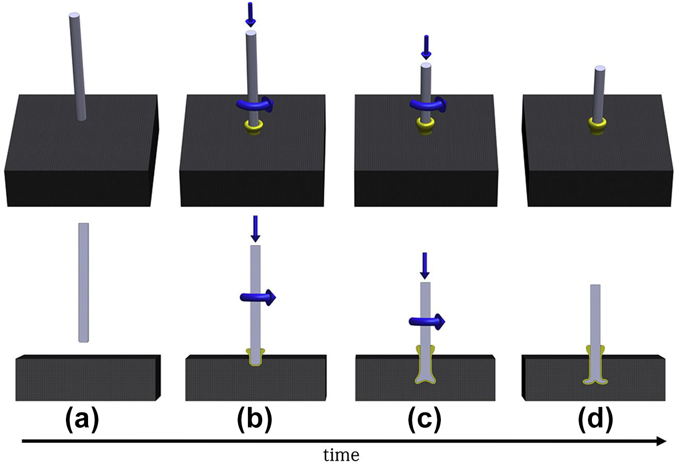
Friction riveting process. (a) Positioning. (b) Frictional heat generation and rivet penetrates the polymer. (c) Increasing the axial force rivet tip widening (mushrooming). (d) Consolidation of joint. 181 Reprinted by permission from Elsevier, 2014.
Additive manufacturing technologies
Additive manufacturing technology is a 3D printing or layered manufacturing technique which is digitally controlled. 189 This technology not only used for polymer but also has made great results for metal, alloys and ceramics.190,191 Figure 27 depicts the mechanism of additive manufacturing. Addjoining process is a novel technique combines Additive manufacturing and materials joining patented by Helmholtz-Zentrum Geesthacht, Germany. AddJoining enables you to layer various materials together in a layered configuration. 192 Fused Deposition Modelling (FDM) is a 3D printing technique involves melting and depositing a polymer layer by layer on a hot bed. Material is melted by a small extruder head with a nozzle through which filament is squeezed. The melted material deposited on the previous solidified layer should properly bonded. Working temperature and pressure plays a major in deposition. 4 Addjoining process is divided into three steps 1. Polymer filament is melted and deposited to form a layered structure. 2. Polymer layer deposited until desired thickness achieved. 3. Hybrid structure was removed from the platform once after the process is completely finished. Bonding between polymer and metal surface done by means of adhesion forces and mechanical interlocking 193 advantages of this 3D printing technologies are possibility to manufacturing complex shapes, variety of material combinations, compared with traditional method structure made by addition technique so wastages of materials less. 194 Disadvantages includes poor accuracy and slow building times. Derazkola et al., 195 manufacture laminated composite structure by using friction stir additive manufacturing (FSAM) between PMMA and textile stainless steel. Where three textile stainless steel was placed between four PMMA sheets. Polymer- steel laminate is obtained by layer upon layer manner. Guo et al. 196 used novel Ultrasonic Additive Manufacturing (UAM) to join AA 6061 – H18 and CFRP. The Samples with 3 layers and 4 layers of Carbon Fiber were built and mechanically tested. Tensile results shows that the peak loads 1.8 mm thick CF plates is 4677 N and for 2.2 mm thick 7238 N. Falck et al. 192 produced joint of AA2024, PA6 and CF-PA6 by using Addjoining technique. Where the lap shear strength obtained is 21.9 MPa which is 19% higher than adhesive bonding technique. Ozlati et al. 197 joined AA5083 and polypropylene PP C30 S used alternate fused deposition modelling additive manufacturing technique by combination of bonding and mechanical locking, this hybrid structure shows good results in tensile shear when they are preheated.
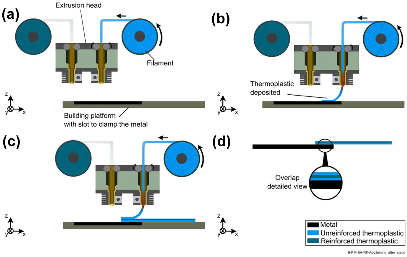
Schematic representation of the Add Joining process for layered metal-polymer composite hybrid structures. 192 Reprinted by permission from Elsevier, 2018.
Challenges in welding dissimilar materials
Even though there is a benefits in weight reduction with the dissimilar metal to polymer joints however joining of these two materials is very challenging due to difference in properties such as melting points, thermal conductivity, thermal expansion and also chemistry of materials.94,198
Following Factors need to be considered while joining dissimilar materials
Heat required to plasticize aluminum can easily deteriorate the polymer, Differences in melting point of materials affects properties of the weld. Thermal conductivity of materials deteriorate the crystallization condition of the materials and affect the wettability of the surface of base materials. Effects of joint stress. Microstructure of joint affected by heating and cooling rates of dissimilar joints. Pre and post heat treatment is useful to reduce minimize thermal stress during joining. Brittle joints may occur due the formation of inter-metallic compounds which results in crack formation at the joint.
Conclusions
Joining of dissimilar metal to polymer using welding technique are still in the early stage of development. In this review article different methods of dissimilar welding of metal to polymer were reviewed. As reported, dissimilar joints were successfully produced by FSW, FSSW, Laser welding, Ultrasonic welding and Induction welding techniques with satisfactory results. This article clearly discussed the properties like tensile strength, microhardness, and microstructure of metal to polymer joints produced by different techniques. This paper also addressed novel types of fabrication method such as friction riveting and additive manufacturing. The following is a summary of the conclusions: The tensile strength of the metal to polymer joint is found low compared to the base material due to difference in composition of the materials. Surface pretreatment like corundum blasting and chemical etching enhances the bonding strength of the weld joint. The microhardness of the metal to polymer joint is low compared to the base metal due to the thermal degradation of the polymer caused by mechanical stirring action of the tool. Since the molten polymer material affected by high frictional heat during the welding process. In FSW technique, Tool rotational speed and transverse speed are the two important parameters which influence the welding quality. Tool rotational speed and plunge depth influences strength of welded joints. So controlling of this parameters are vital to increase weld quality. Bubbles and voids formation due to the elevated temperature which reduces load bearing capacity of the joints. This can be eliminated by decreasing the heat input. Macro mechanical and adhesion bonding are the primary bonding mechanism in between metal and polymer welds produced by FSW technique. Friction stir spot joining is the alternate process for FSW. Only low thermal degradation occurs when compared to the traditional FSW process, which benefits in improvement of joint properties. The interfacial region between resolidified polymer and metal alloys is the most important factor influencing joint strength during the laser welding process. Due to the high heat production microstructures of joints produced by laser welding present in this region clearly shows the brittle structures, results in reduction of mechanical properties. Surface pre-treatment improves strength of the joints. Ultrasonic welding technique produced good sound weld when compared to other process, but only limitation is only thin sheets joined by this technique. Maximum seam size is not larger than 250 x 300 mm and special tooling is required for complex shapes and it is costly. Friction riveting are also novel type joining techniques to produce the dissimilar joints. Friction riveting doesn’t need any special surface preparation and curing agents compared with other process. This technique also reduces stress concentration in joints. In recent years, advanced joining technologies such as Additive manufacturing have been developed to improve accuracy of the joints with less wastage of material. Major advantage of this technique that it is easily automated in manufacturing and more degree of freedom in machining complex parts.
Based on existing literature survey we found the following need to be addressed in further studies: Theoretical discussion on internal material flow at the metal to polymer interface during welding must be addressed. To investigate the heat generation during dissimilar welding of metal to polymer numerical simulation studies should be addressed. It will also reduce the material wastage. There has been no proper research into the effect of shrinkage and structural change in polymer structures caused by heat produced during joining. No proper studies addressed in area of corrosion and fatigue loading which is very much important in automated industries. Welding of metal to polymer will become hot topic in coming years.
Footnotes
Declaration of conflicting interests
The author(s) declared no potential conflicts of interest with respect to the research, authorship, and/or publication of this article.
Funding
The author(s) received no financial support for the research, authorship, and/or publication of this article.