
Abstract
Present paper has experimentally and numerically investigated the mechanical behavior of composite sandwich panel with novel M-shaped lattice core subjected to three-point bending and compressive loads. For this purpose, a composite sandwich panel with M-shaped core made of carbon fiber has been fabricated in this experiment. In order to fabricate the sandwich panels, the vacuum assisted resin transfer molding (VARTM) has been used to achieve a laminate without any fault. Afterward, polyurethane foam with density of 80 kg/m3 has been injected into the core of the sandwich panel. Then, a unique design was presented to sandwich panel cores. The study of force-displacement curves obtained from sandwich panel compression and three-point bending tests, showed that an optimum mechanical strength with a considerable lightweight. It should be noted that the experimental data was compared to numerical simulation in ABAQUS software. According to the results, polyurethane foam has improved the flexural strength of sandwich panels by 14% while this improvement for compressive strength is equal to 23%. As well as, it turned out that numerical results are in good agreement with experimental ones and make it possible to use simulation instead of time-consuming experimental procedures for design and analysis.
Introduction
Sandwich panels are made of two plates, top and bottom, with a lattice core, both of which are made of composite material. High strength-to-weight ratio is the main characteristic in the sandwich panels. 1 The main role of lattice core is to keep the surface sheets separated and make the whole panel to resist against vertical deformations like a single plate. Composite sandwich panels with lattice cores have wide applications in the industries of transportation, automotive, aerospace and also marine structures due to low weight and high strength. The geometry of the lattice core has a great effect on load distribution. 2 Many researches have been performed on the mechanical and properties of the composite sandwich panels such as compressive strength, three-point bending strength and specific bending strength.
Mechanical properties of multilayer corrugated core laminated composite sandwich panel under quasi-static three-point bending are investigated experimentally as well as numerically by Farrokhabadi et al. 3 According to the experimental and numerical results obtained from different quasi-static bending tests, 3 it was found that the composite multilayer specimen A-03, composed of rectangular core shape, exhibited the highest capability of energy absorption, maximum deflection and minimum peak load; while, the composite sample C-03, composed of triangular core shape, showed the maximum value of peak load, minimum absorbed energy and deflection up to fully penetration. Jen and Tang 4 performed the four-point bending tests on the sandwich beam with glass/polypropylene faces and aluminum foam cores and experimentally studied the effects of face thickness, core height, and angle-ply directions on the bending strengths and the failure modes of the studied sandwich panel. Assessment results showed that the prediction errors were found to be below 30% for most specimens. Akhmet et al. 5 Analyzed the performance of adhesively bonded corrugated core sandwich structures using cohesive zone method. Sayahlatifi et al. 6 numerically and experimentally studied the quasi-static behavior of hybrid corrugated composite/balsa core sandwich structures in four-point bending. The parametric study showed that with increasing the corrugation angle and thickness, the specific strength/stiffness exhibited an ascending trend. Moreover, rectangular-shaped corrugation contributed to the best mechanical performance. Florence et al. 7 studied the effect of energy-absorbing materials on the mechanical behavior of hybrid fiber-reinforced plastic honeycomb core sandwich composites which were under the three-point bending, edgewise compression, flatwise compression and Charpy impact. Ma et al. 8 carried out the bending fatigue tests of honeycomb sandwich panels by using an improved three-point bending test. A life prediction method was proposed and its effectiveness in predicting the fatigue life of sandwich panels has been verified.
Joseph et al. 9 analytically and experimentally presented the results of Flexural behavior of concrete sandwich panels subjected to punching load and four-point bending. Numerical models developed were able to approximately predict load-deflection responses of concrete sandwich panels under different loading conditions. Zhou et al. 10 developed a low-cost alternative method for the evaluation of residual compressive strengths of sandwich panels via four-point bending. It was found that core density and compressive skin thickness were the major factors of significantly influencing the failure modes of the sandwich beams. Wang et al. 11 studied the bending resistance performance of the honeycomb sandwich panel with ceramic tile face-sheet through three-point bending experiments. The results demonstrated that the bending behavior of the present ceramic sandwich was largely promoted due to the ceramic tile face-sheet. Besides, the mechanical influence of the ceramic tile face-sheet and the cell edge length of honeycomb core were determined. Sun et al. 12 introduced the short-Kevlar-fiber toughening method for three-point bending and in-plane compression properties of carbon-fiber/aluminum-honeycomb sandwich panels. Formisano et al. 13 studied the mechanical behavior and collapse mechanisms of innovative aluminum foam-based sandwich panels exposed to three-point bending. Sun et al. 12 performed both three-point bending and in-panel compression tests on aluminum honeycomb sandwich panels to explore the crushing behaviors of honeycomb sandwiches. Based on the experimental results, theoretical solutions for the three-point bending test were also established to predict the peak load, energy absorption and collapse mode. Wang et al. 14 presented a numerical study on three-point bending behavior of honeycomb sandwich with ceramic tile. The ceramic sandwich with reinforced honeycomb core also showed better mechanical behavior in the simulation. Rupp et al. 15 focused on failure mode maps of sandwich panels under bending load, which have been produced using a polyurethane spraying process. Cinar 16 evaluated of sandwich panels with composite tube-reinforced foam core expose to bending and flatwise compression. According to the test results, the samples including the composite tubes gave six times higher bending stiffness as compared to the samples without the composite tubes. Shah and Kapania 17 analyzed the failure of hexagonal and triangular honeycomb core sandwich panels subjected to three-point bending, in-plane compressive loading, and transverse shear loading using finite element method. The comparison made between triangular core and hexagonal core sandwich panels having the same cell size and relative density showed that triangular cores outperform hexagonal cores for applications where in-plane loading is dominant, whereas, in terms of transverse shear and out-of-plane loading, triangular core panels tend to fail at lower loads and lower deflections. Djama et al. 18 fabricated a sandwich panel composed of hybrid skins and novel glass fiber-reinforced polymer truss core using a novel manufacturing method to analyze the mechanical behavior of the sandwich panel. A comparison with a few common lightweight structures indicated that the manufactured truss core had similar specific compressive and shear strengths.
Gao et al. 19 experimentally studied the bending behavior of ZrO2 honeycomb sandwich structures prepared by digital light processing’s tereo lithography. Uzay et al. 20 presented mechanical behavior of sandwich structures with eight different fiber facing configurations and extremely low-density foam cores via three-point bending load. Wang et al. 21 investigated the effects of core thickness and density on strength, stiffness, and panel peeling strength of carbon fiber-reinforced composite sandwich structures. The results showed that material strength improved by increasing the density or thickness in their structure. Demircan et al. 22 obtained tensile and bending properties of biaxial weft-knitted and cross-ply thermoplastic composites. According to their investigation, tensile and three-point bending properties of the cross-ply composite structures had higher than the biaxial weft-knitted composites with the aramid stitch yarn Because of the higher volume fraction of the cross-ply composites. Hu et al. 23 experimentally revealed the deformation, strength, and failure modes of woven textile sandwich composites to carry out flatwise and edgewise compression experiments, uniaxial stretching experiments, and three-point bending experiments. Three-point bending and tribological properties of surface-treated poly fiber-reinforced high-density polyethylene composite have been considered by Li et al. 24
To the best knowledge of the authors, it can be figured out that there is no study for investigation of damage analysis in composite sandwich panels with novel M-shaped lattice core expose to three-point bending load and compressive load. This paper experimentally and numerically represents the mechanical behavior of composite sandwich panels with novel M-shaped lattice core composed of carbon fibers and Epoxy resin subjected to three-point bending load and compressive load. All samples manufactured and also simulated in ABAQUS software. The principal purposes of the paper are i) Inventing a new design for truss core in order to reach the high level of mechanical strength by following engineering standards and ii) the influence of polyurethane foam on the mechanical behavior of the sandwich panel under bending load and compressive load is investigated.
Materials description and design and fabrication steps
In this research, in order to manufacture the sandwich panel with M-shaped core, epoxy resin EC 130 LV have been used which its properties are shown in Table 1. Woven carbon fibers (ρs = 1760 kg/m3) with the properties shown in Table 2 are used to fabricate the laminates. Another material that has been used in this study is polyurethane foam, whose material properties have been shown in Table 3.
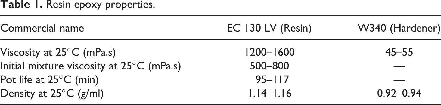
Resin epoxy properties.
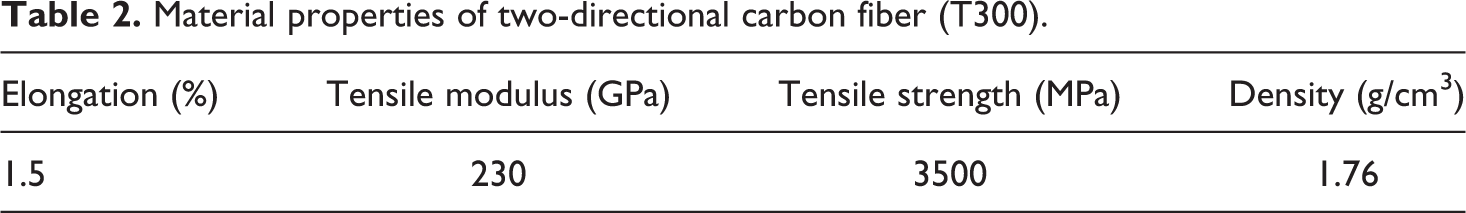
Material properties of two-directional carbon fiber (T300).
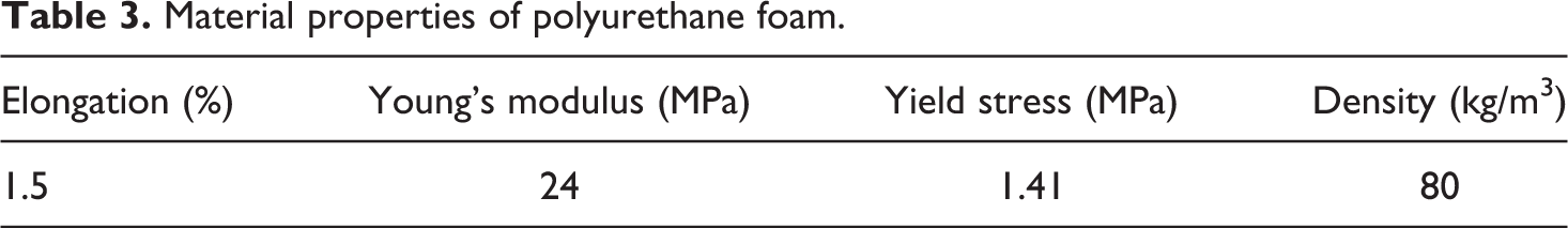
Material properties of polyurethane foam.
Generally, the fabrication of the sandwich panels has three important steps. In the first step, the carbon fiber is cut in a appropriate size and then they are placed in a vacuum bag and resin epoxy is added. Afterward, in order to heating and cooking process, they’re placed in oven machine. In the second step, the produced laminates are cut by water jet in designed size according to the plan. And finally, in the third step, The male-female parts, which produced by water jet, are assembled together to form the core. Then, resin epoxy is used again in order to attach the upper and lower plates to the core. Oven machine is used again to cook the epoxy resin in the region of connection of plates and core. It should be noted that the manufacturing and assembly process is similar for all samples. More details have been provided in the next two subsections.
Laminates production
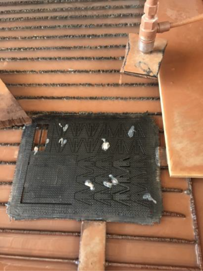
In this section, the design and fabrication steps of sandwich panel with M-shaped core has been introduced. In order to achieve a laminate without any porosity, the method of Vacuum Assisted Resin Transfer Molding (VARTM) has been used in the first step. The epoxy resin was subjected to a frequency of 30 kHz and a power of 150 W for 10 min by an ultrasonic device, at which point the hardener was added to the mixture in a ratio of 100 to 15. In this process, after placing the carbon fibers in the vacuum bag (Figure 1) and creating a partly vacuum on it, the resin pass through the mold from inside the tube so that the whole bag is filled evenly. The produced laminate includes eight layers of carbon fiber woven with epoxy resin. The fabricated samples are vacuum placed for 12 h at room temperature to be completely dried. Eventually, the samples are then placed in an oven at temperature of 60°C for 4 h. All laminates have almost 1.95–2.05 mm thickness.
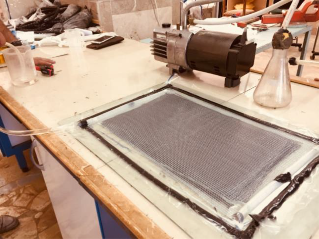
Vacuum bag pump.
Sandwich panel fabrication
The next step is to build sandwich panel with novel M-shaped core. The composite sandwich panel consists of two face-sheets and M-shaped lattice core (Figure 2). The M-shaped core is composed of three female parts and three male parts that every part has three trapezoidal unit cells. The truss-shaped core components have been designed as male and female parts in way that be assembled to each other without any need to glue. The dimensions of the female and the male parts have been shown in Figure 3.
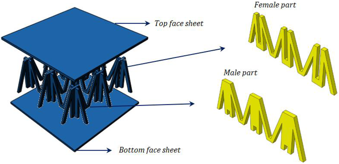
Configuration of composite sandwich panel with M-shaped lattice core.
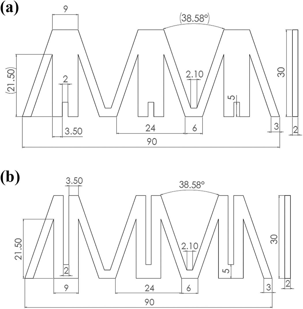
Dimensions of (a) male and (b) female part (in mm).
The laminates are cut by water jet cutting operation to make the female parts and male parts according to the construction plan (Figure 4). Then, the resulting patterns were assembled into each other with male-female fitting to produce a M-shaped lattice core (Figure 5). As seen in Figure 2, the two face-sheets, which have dimension of 90 mm length, 90 mm width and 2 mm thickness, are placed on the top and bottom of the core with epoxy resin. To attach the laminates to the core, sandwich panels are placed inside the oven. In order to make a strong connection between the core and plates, the samples should be placed inside the oven for 9 h at 40°C for more complete cooking. To perform the mechanical experiment on the panels, three sandwich panel have been fabricated for each experiment. Finally, sandwich panel was fabricated with dimensions of 90 mm × 90 mm × 34 mm (Figure 6(a)). Then polyurethane foam, which is obtained by combining two materials: polyol and isocyanate, with a density of 80 kg/m 3 has been used to fill the empty space between the M-type core and the sandwich panel surfaces. Finally, the foam-filled sandwich panel was made as shown in Figure 6(b).
Cutting laminate by waterjet machine.
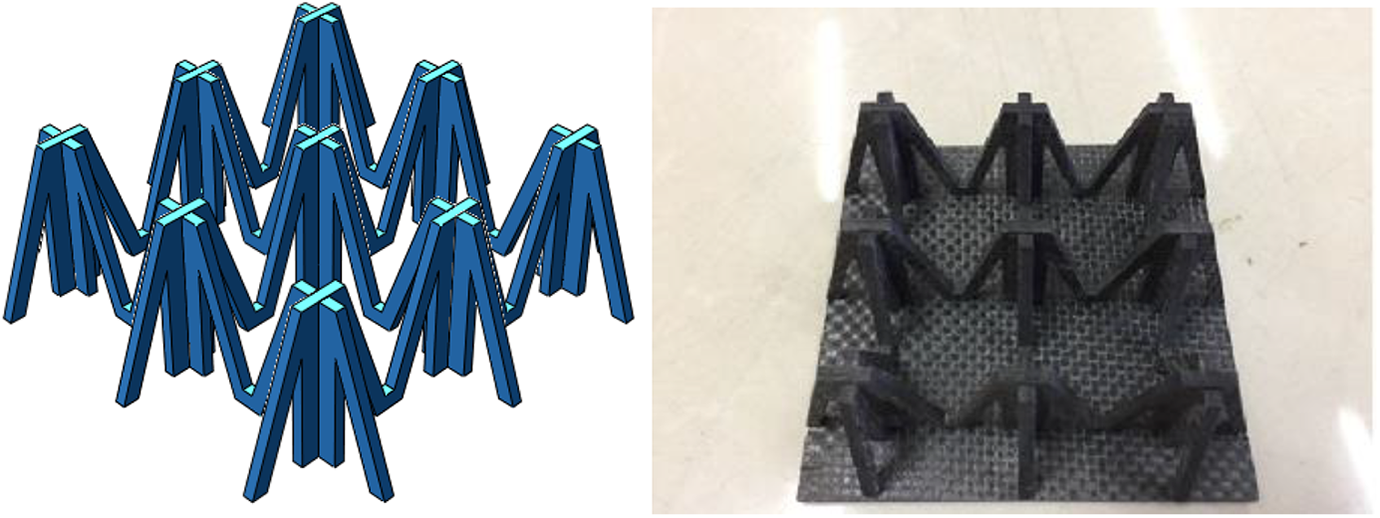
Fabricated M-shaped lattice core.
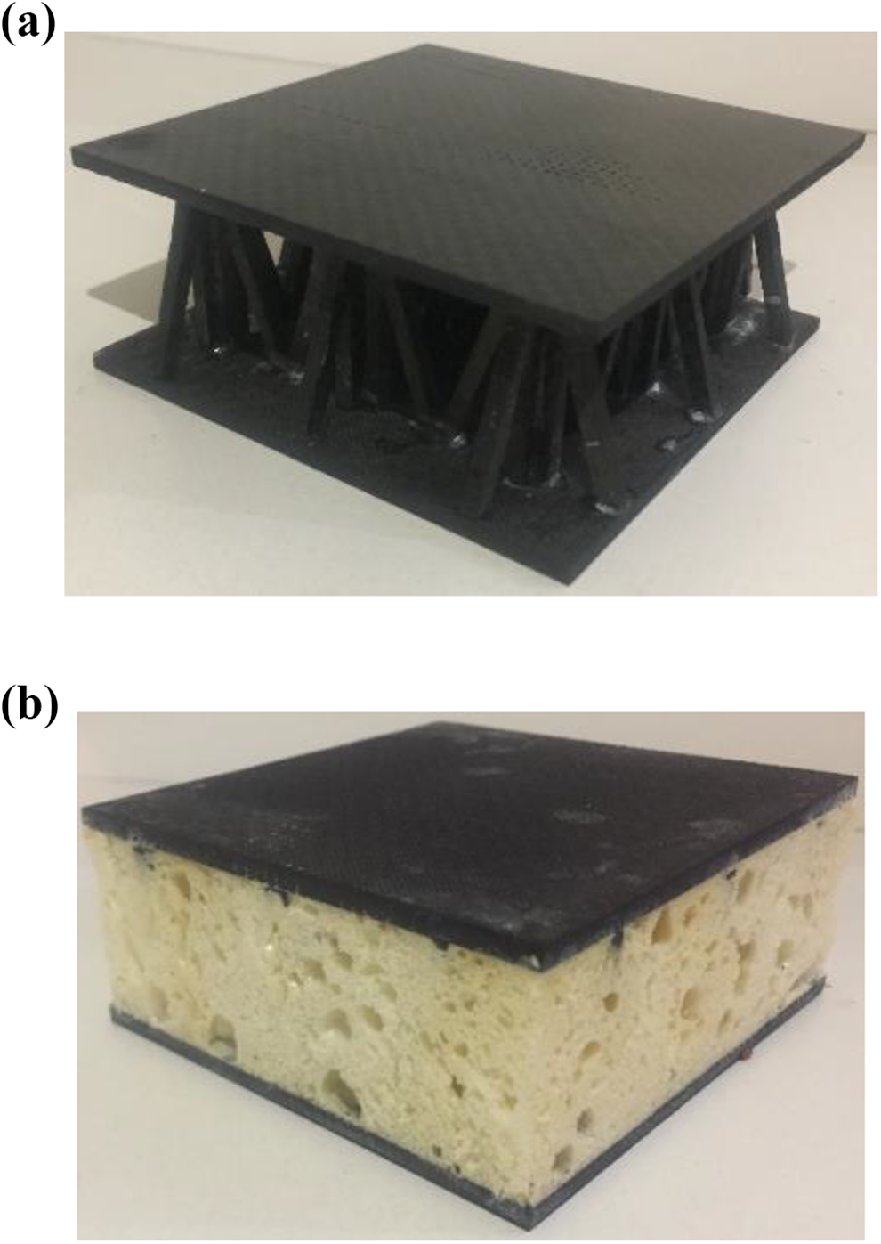
Fabricated composite sandwich panel (a) with foam and (b) with foam.
Experimental tests
All of the mechanical tests in the present research were done by a SANTAM testing machine with axial actuators. The SANTAM has a static capacity of 150 KN, with a maximum stroke of 300 mm. Aappropriate movement rate of the movable head of the testing machines is between 0.5 and 10 millimeter per minute. 25 In this study, the speed rate of 0.5 mm/min has been applied through all types of mechanical tests to get the maximum accuracy for taking picture from different failure modes.
Tensile test
The laminates were tested in tensile properties direction in order to determine the mechanical properties of the parent material used to manufacture the lattice cores and laminate sheets. As mentioned, tests were conducted on rectangular specimens accordance with ASTM D-3039 by using SANTAM STM-150 hydraulic device as shown in Figure 7. And also the carbon fiber laminates used in the tensile test has been shown in this figure. The constant movement rate of movable head of the testing machine was 0.5 mm/min. The gages under test is rectangular-shaped with dimensions of 250 mm × 25 mm × 2 mm (Figure 7).
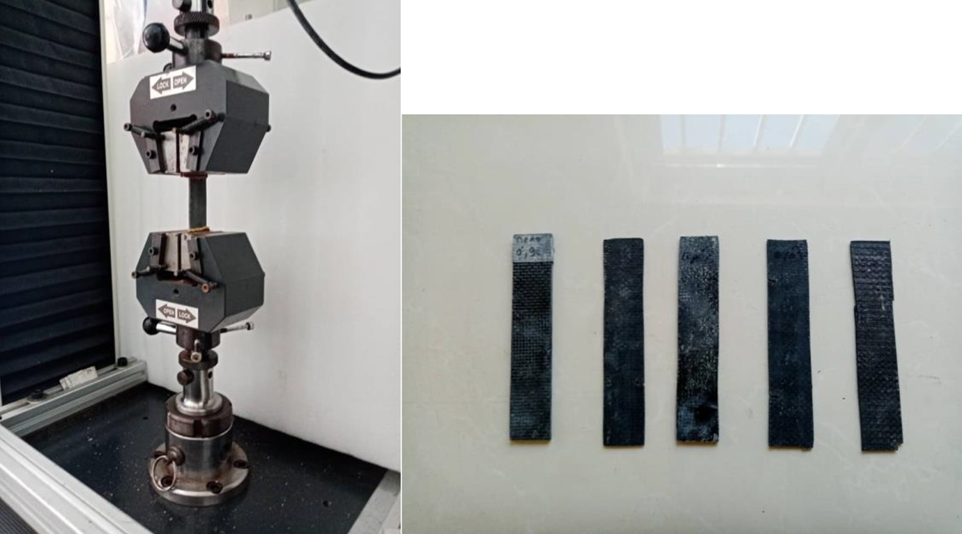
Testing machine in conjunction with carbon fiber laminates in the tensile test.
Three-point bending test
In order to determine the mechanical behavior of the composite sandwich panel, three-point bending test using a cylindrical rod with a 9 mm radius is implemented. And then, the stress-strain curves of the composite panel is obtained. It is necessary to mention that the three-point bending tests in the current study were performed by a SANTAM STM-150 testing machine with axial actuators. Figure 8 shows the specimen mounted on the testing machine and ABAQUS software.
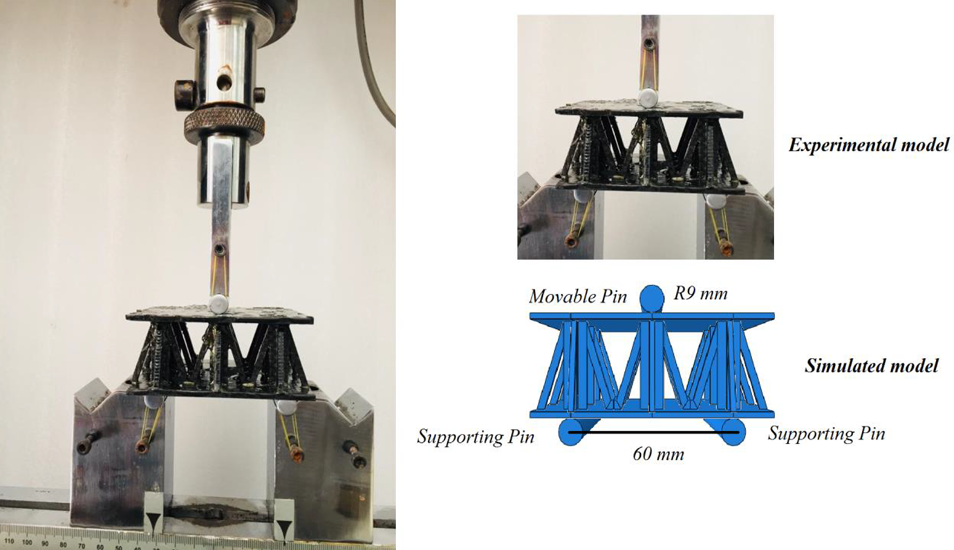
Sandwich panel with M-shaped core during three-point bending test.
Compressive test
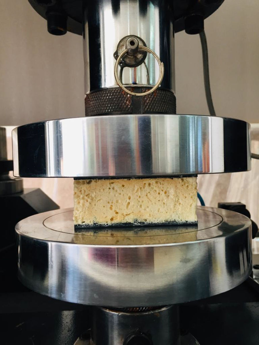
In order to determine the compression behavior of the composite sandwich panel, compressive load has been applied on the panels. Single laps flatwise compressive tests were conducted on the M-shaped core panels in accordance with the standard test for sandwich core material. Flatwise compression tests were performed according to ASTM C365 test standard. For the flatwise compression test, the specimen with an area of 90 mm × 90 mm were put on a self-aligning spherical bearing block. Figure 9 shows the specimen mounted on the testing machine and ABAQUS software.
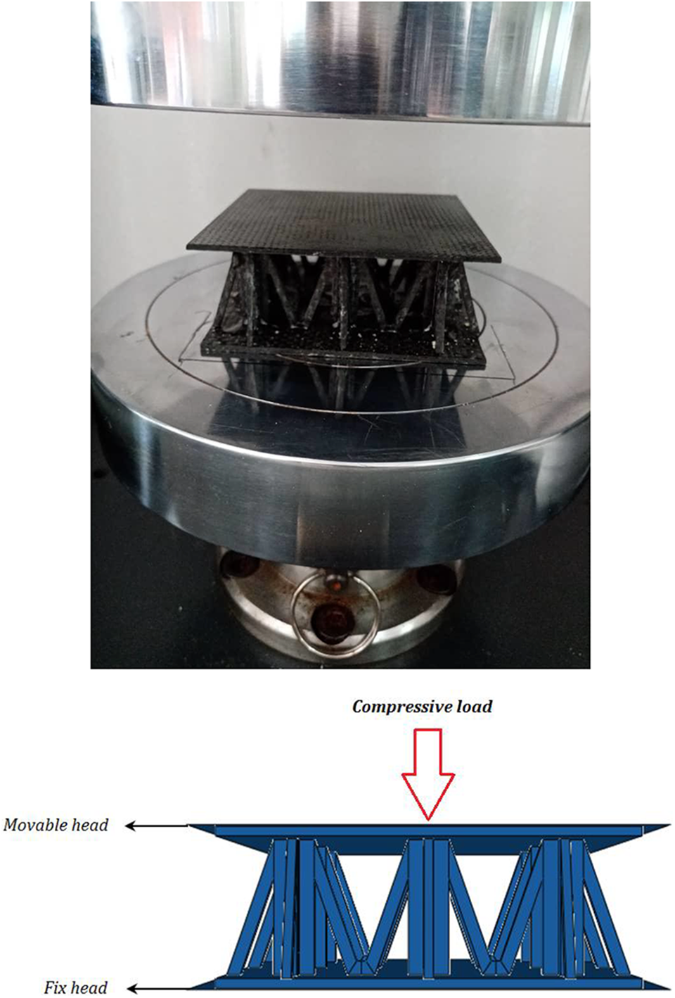
Flatwise compression test setup during the comparison test.
Numerical solution
In this section, the details of numerical modeling are explained. In order to validation of the results in the tensile, three-point bending and compression tests, finite element method (FEM) has been used to compare the numerical and experimental results. Therefore, the numerical simulation has been performed by ABAQUS well-known software, which some of the important steps are expressed in the following subsections.
Geometrical modeling
The first step is to define the geometry of sandwich panels with M-shaped core according to the experimental model. To model the sandwich panels for three-point bending and compressive tests, a 3D, solid and deformable part has been designed. The dimensions of the sandwich panel were shown in the Figure 3.
Property assigning
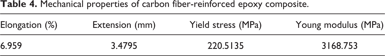
After modeling the fabricated panel, the mechanical properties need to be assigned to the samples. For this purpose, the mechanical properties of carbon fiber-reinforced epoxy composite have been experimentally determined in tensile tests (see Table 4 and Figure 10). Also, the pins and the supporting plates behaviors in the bending and compressive analysis are considered rigid due to their negligible deformation in comparison to the sandwich specimens. The contact behavior between the composite specimens and the pins is set to be frictional with 0.3 as coefficient of friction.
Mechanical properties of carbon fiber-reinforced epoxy composite.
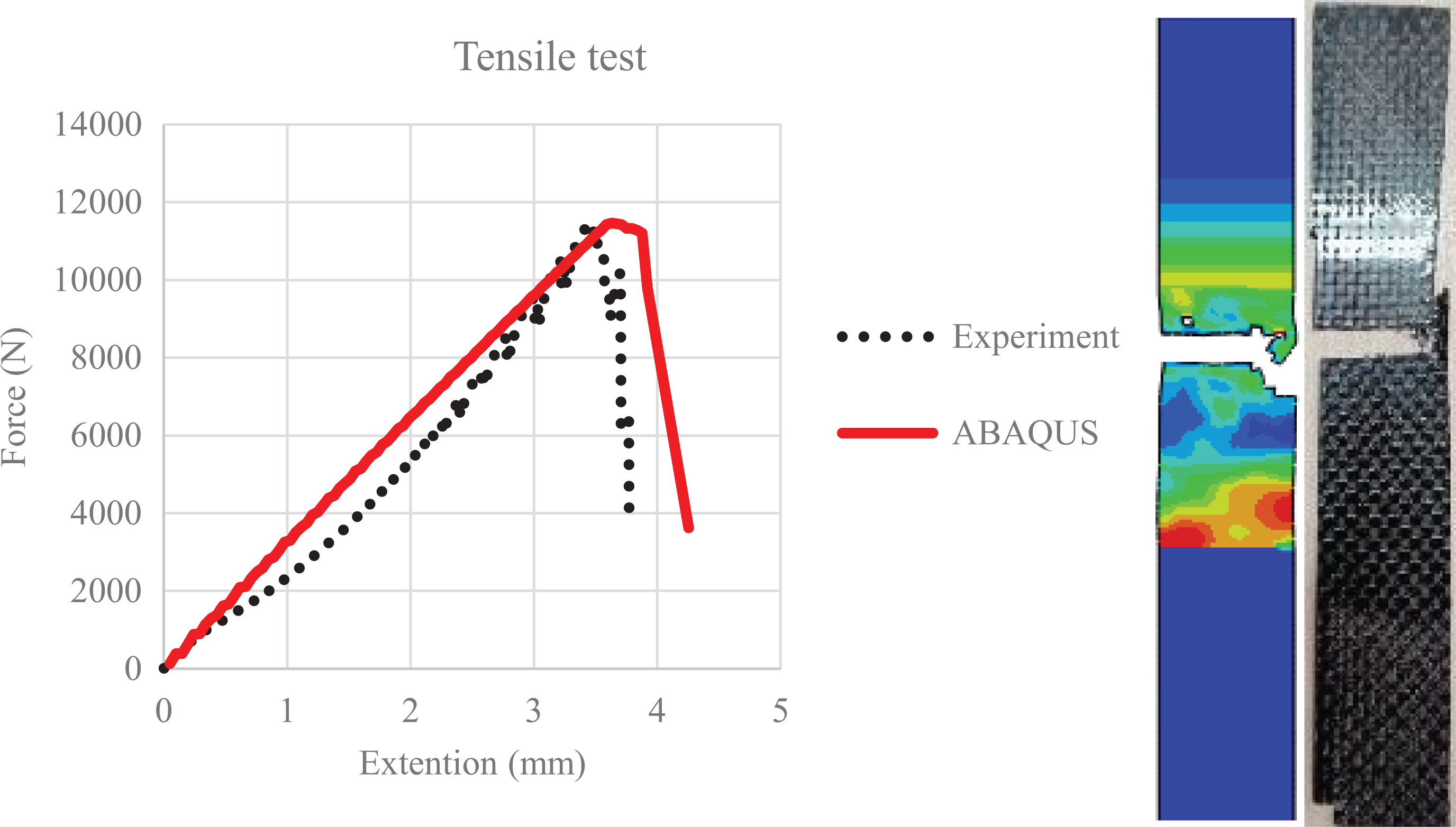
Force-displacement diagram and simulated fracture mode of sample under tensile test.
Mesh and element type
In this analysis, the eight-side element C3D8R has been used for meshing the part instances of the composite samples. The convergence study has been performed to find the proper size of the elements. It is necessary to mention that the optimal number of panel’s elements are 78766.
Boundary conditions
In the bending test, supporting pins of the bottom of the panel has been fixed in all directions and the movable pin of the top of the panel is also constrained in all directions except transverse direction, which is free in y-direction. Furthermore, in order to apply the bending load, 14 mm displacement in y-direction is applied to the top pin. Transverse displacement is performed until the moment of failure of the part (see Figure 8). Also in the compressive test, the fixed head of the bottom of the panel has been fixed in all directions and the movable head of the top of the panel is also constrained in all directions except transverse direction, which is free in y-direction. Furthermore, in order to apply the compressive load, 10 mm displacement in -y-direction is applied to the movable head (see Figure 9). Transverse displacement is performed until the moment of failure of the part.
Step
In the present simulation, the dynamic explicit solver has been used to analyze the bending and compression behaviors of the panels. It should be noted that the explicit analysis, unlike the implicit analysis, never encounters the problem of non-convergence after the occurrence of damage in which the properties of the material degrade.
Convergence study
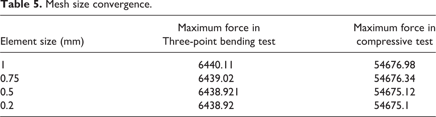
In this section, A mesh convergence analysis is performed to balance the accuracy and computational cost. According to the Table 5, maximum force in the three-point bending test and compressive test has been determined for different mesh size in the simulation. Table 5 shows the results for the 0.2 mm mesh size are close to the results of 1.0 mm mesh size. But, the results for the 0.2 mm mesh size are closer to the experiment results. However, the running time is almost equal for both mesh sizes. Therefore, a mesh size of 0.2 mm is chosen for simulation of mechanical tests.
Mesh size convergence.
Results and discussion
In this study, the manufactured sandwich panels foam-filled and without foam have been subjected to the three-point bending and compressive loads for same conditions for each sandwich panel, their mechanical behaviors have been examined experimentally as well as numerically.
Results of tensile strength
Figure 10 indicates force-displacement diagram that has been obtained from the numerical and experimental tensile test data for carbon fiber material. As shown in Figure 10, the experimental results have excellent agreements with those obtained by numerical simulation. Table 6 also shows the maximum force in experiment and simulation tensile test. It can be figured out from the comparing the results in both method, difference between them is approximately 0.04%. Eventually, Figure 10 shows that by increasing the tensile load, the curve remain in elastic region.
Maximum force in experimental and numerical tensile test.

Results of three-point bending test
In this section, the results of three-point bending test on sandwich panels with M-shaped core have been presented. Figure 11 illustrates the force-displacement diagram of M-shaped composite sandwich panel exposed to three-point bending load experimentally as well as numerically. As this figure shows, the numerical simulation is well capable to predict the bending behavior of sandwich panels and there is a fairly good agreement between the experimental and numerical results such that the difference between maximum stress in the loading process is less than 2%. It should be noted that one of the inevitable errors in the simulation is boundary conditions. Because it has been defined three types of boundary condition in ABAQUS software such as free, clamped and simply supports while in the experiment situation, the boundary conditions are not exactly similar to them. For example, in the fixed boundaries, node displacement is exactly zero in the simulation while, in the experiment, the node displacement have a little value and is not exactly zero. Therefore, to displace the sandwich panels or other samples for the special value, more force is required in the simulation than in the experiments. In other words, the elastic part of the simulation curve in Figure 11 is steeper than in the experiments. On the other hand, despite the inevitable errors, the developed numerical model predicts the peak loads of the samples reasonably well and the overall numerical solution process trend corresponds to experimental one. As seen from this figure, the elastic region started at point O and ended at about point A and after that, the plastic region started and then, at point B, plastic region ended and then the crushing behavior is abruptly happened. It is clear that there is no fault in the region of the elastic response in samples (Figure 12(a)). The pinging noises were observed continuously after the peak load with widespread damage due to crushing after about point A the photograph of the specimen is shown in Figure 12(b) and (c) to visually elucidate the failure modes observed experimentally. This observation has been considered on some previous study. 26
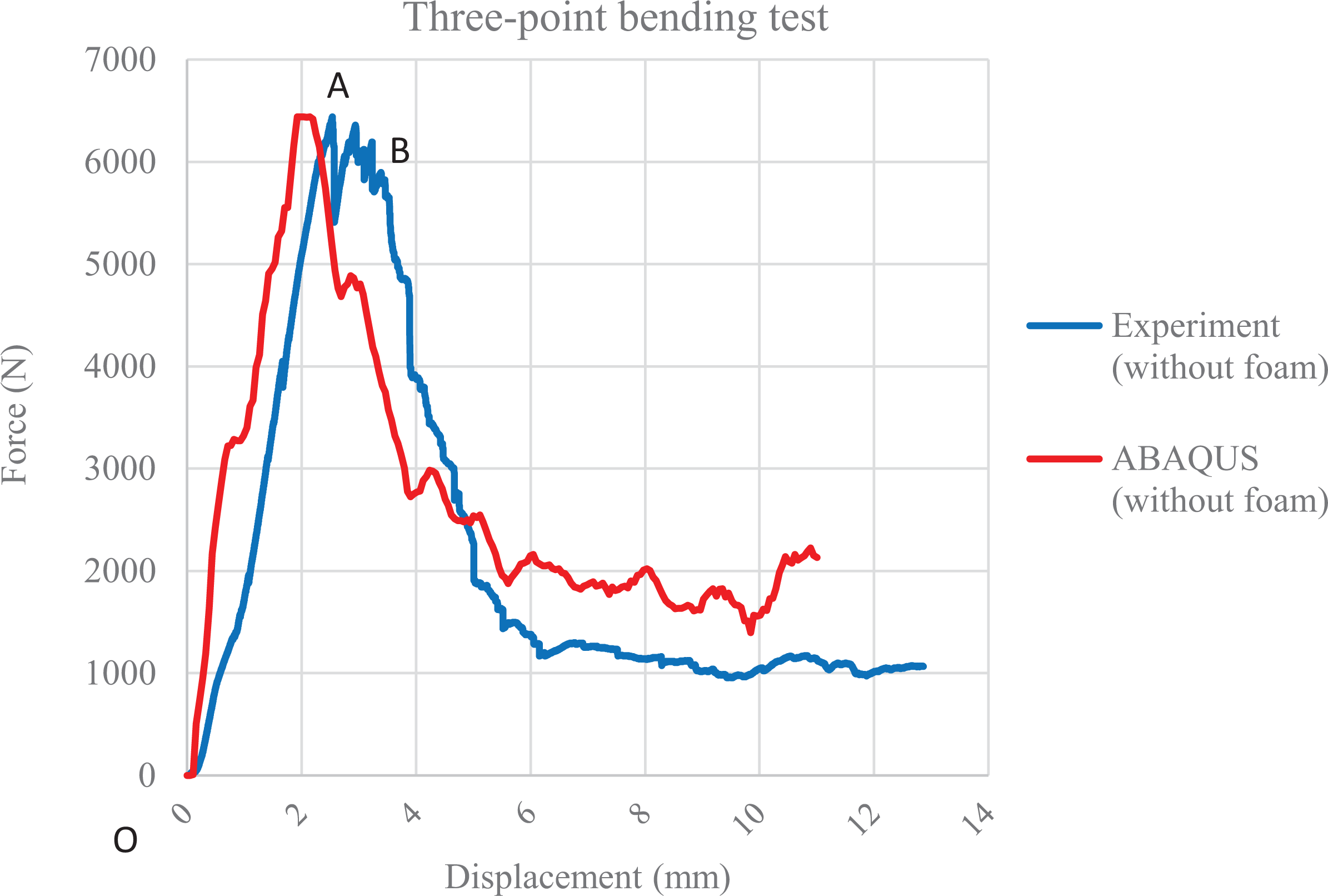
Force-displacement diagram of the M-shaped composite sandwich panel under three-point bending test in numerical and experimental method.
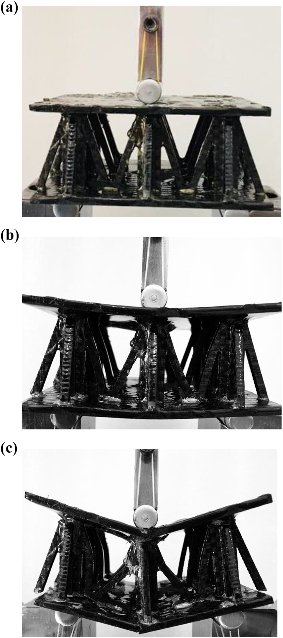
Deformation history and failure modes. (a) Elastic response. (b and c) Fracture modes from point B region.
Figure 13 compares the results of damage and failure mechanisms of the M-shaped sandwich panel samples in the numerical analysis with the experimental results. It is necessary to notice that these results belong to the damage mechanisms at the last step of loading. As the figure shows, the software presents the deformations and damages in the sample reasonably well.
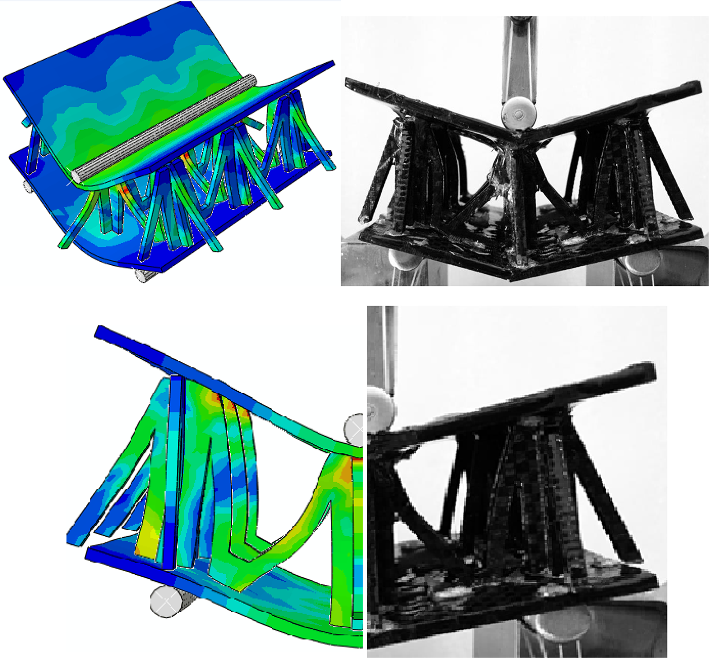
Comparing experimental and numerical damage mechanisms under three-point bending load.
For better understanding, the numerical and experimental results of M-shaped sandwich panel structures are compared and analyzed. Based on the obtained data in Table 7, the difference between the numerical and experimental results on anticipating the maximum stress is about 0.01% on average and generally there is an good agreement between numerical and experimental results.
Maximum force in experimental and numerical bending test.
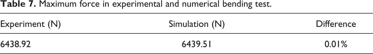
Figure 14 shows the experimental damage mechanism of the M-shaped composite sandwich panel with polyurethane foam subjected to three-point bending test. Figure 15 illustrates the force-displacement curves for foam-filled and non-foam-filled composite sandwich panel under three-point bending test. It is figured out that polyurethane foam has great influence on bending behavior of the sandwich panel and the peak load in the foam-filled sandwich panel is about 14% more than that in the foamless sandwich panel and point B’ is higher than before (B). The maximum force in foamless and foam-filled sandwich panels under three-point bending have been shown in Table 8.
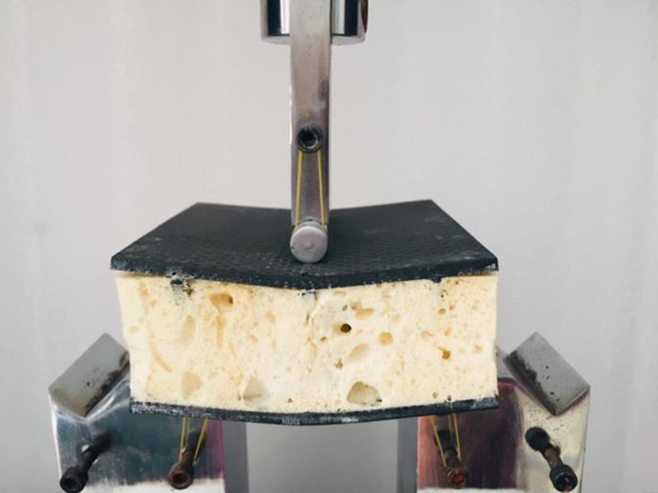
Foam-filled sandwich panel under three-point bending load.
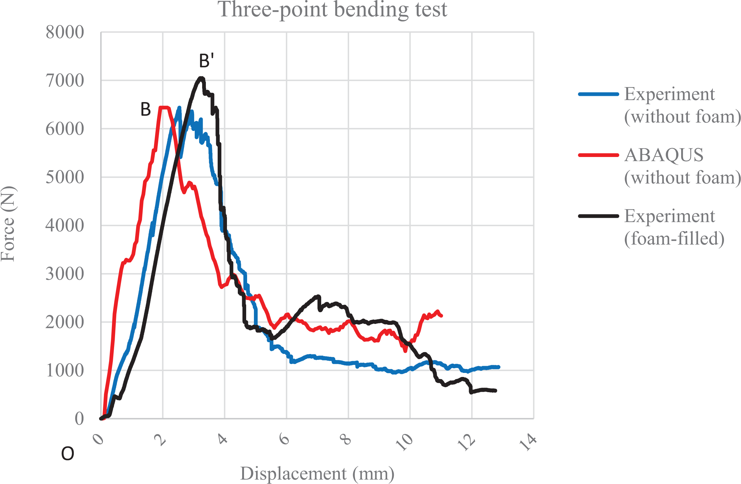
Comparison of stress-strain diagram of the M-shaped composite sandwich panel under three-point bending test in experimental and numerical simulation.
Maximum force for foamless and foam-filled sandwich panel under three-point bending test.
Results of compressive test
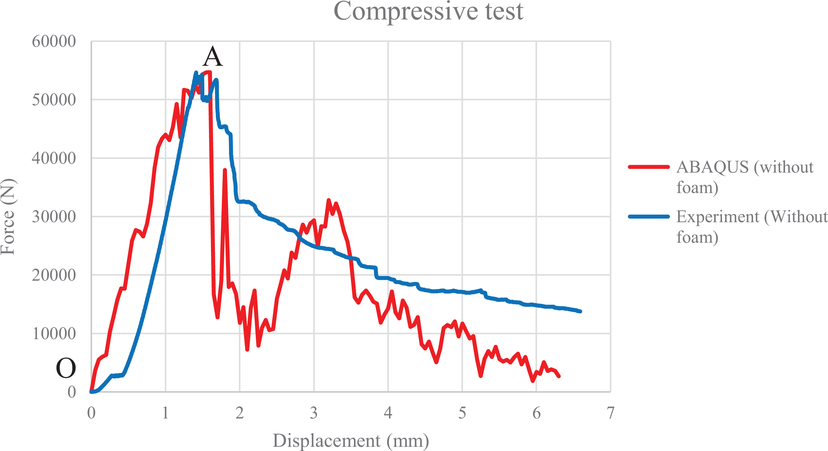
Figure 16 compares the predicted flat wise compressive strength panels with test results. According to the figure, the developed numerical model predicts the peak loads of the samples reasonably good and the overall numerical solution process trend corresponds to test one. As the figure shows, the elastic region started at point O and ended at about point A and after that, the crushing behavior is abruptly happened. It is clear that there is no fault in the region of the elastic response in samples (Figure 17(a)). The pinging noises were observed continuously after the peak load with widespread damage due to crushing after about point A the photograph of the specimen is shown in Figure 17(b) and (c) to visually elucidate the failure modes observed experimentally.
Force-displacement diagram of the M-shaped composite sandwich panel under compressive test in numerical and experimental method.
Deformation history and failure modes: (a) Elastic response. (b and c) Fracture modes from point A region.
Figure 18 illustrates the results of damage and failure mechanisms of the M-shaped sandwich panel under compressive load in the numerical analysis and the experimental results. It is important to notice that these results belong to the damage mechanisms at the last step of loading. As the figure shows, the software presents the deformations and damages in the sample reasonably well.
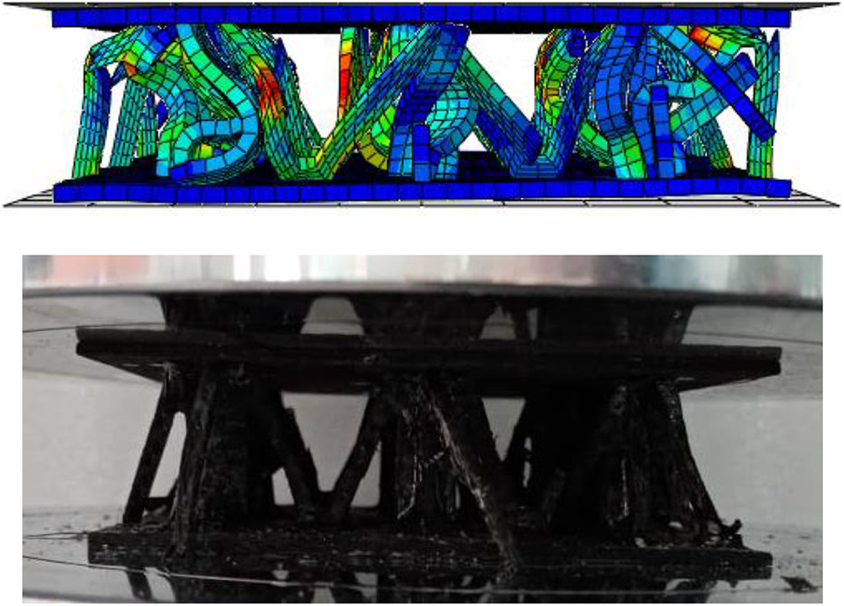
Comparing experimental and numerical damage mechanisms under compressive load.
In addition, the numerical and experimental results of M-shaped sandwich panel structures are compared and analyzed. According to the obtained data in Table 9, the discrepancy between the numerical and experimental results on anticipating the maximum load is about 0.07% on average and generally there is an excellent agreement between numerical and experimental results.
Maximum force in experimental and numerical compressive test.
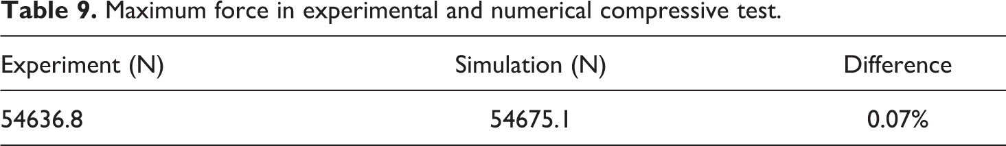
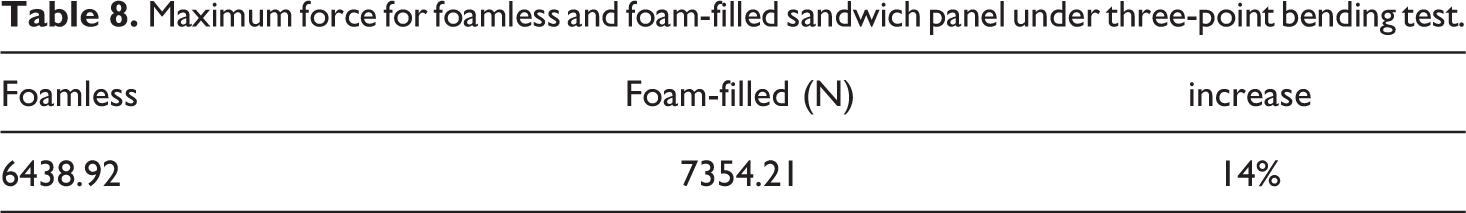
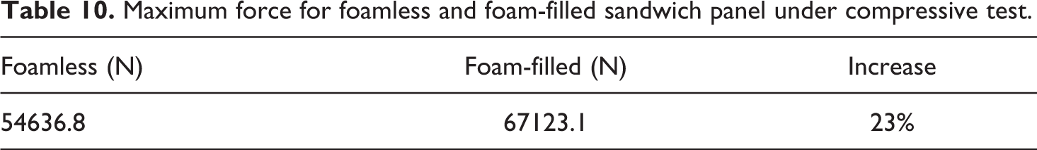
Figure 19 shows the experimental damage mechanism of the M-shaped composite sandwich panel with polyurethane foam subjected to compressive test. Figure 20 illustrates the force-displacement curves for foam-filled and non-foam-filled composite sandwich panel under compressive test. It is figured out that polyurethane foam has great influence on compressive strength of the sandwich panel and the peak load in the foam-filled sandwich panel is about 23% more than that in the foamless sandwich panel and point A’ is higher than before (A). The maximum force in foamless and foam-filled sandwich panels under compressive force have been illustrated in Table 10.
Experimental damage mechanism under compressive load.
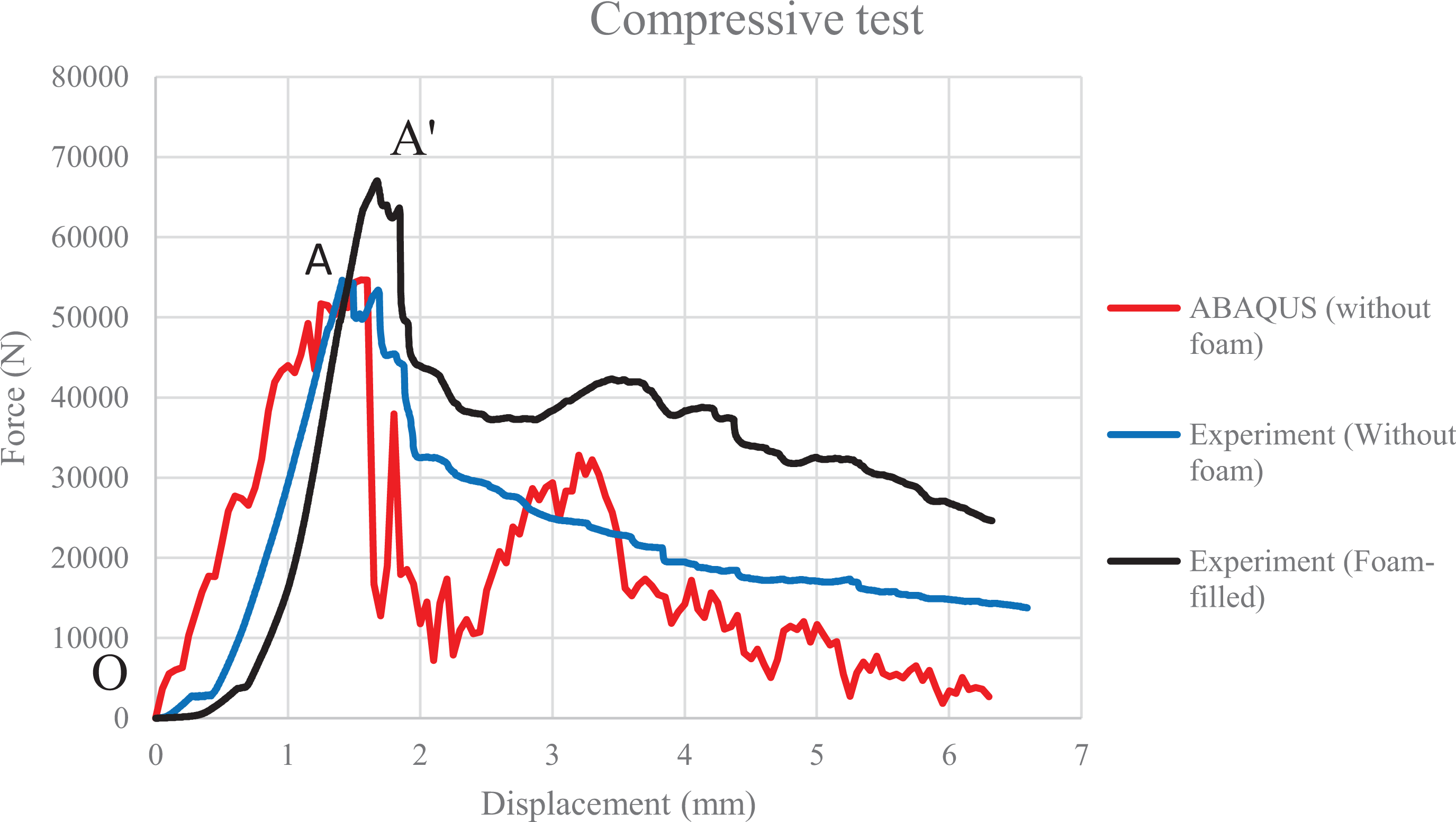
Comparison of force-displacement diagram of the M-shaped composite sandwich panel under compressive test in experimental and numerical simulation.
Maximum force for foamless and foam-filled sandwich panel under compressive test.
Conclusion
In order to evaluate the flexural strength of the all-composite sandwich panels with novel M-shaped core design, the Polyurethane (PU) foam-filled and non-filled core sandwich structures were fabricated and flatwise-compression and three-point bending tests were performed. All the specimens, were prepared with eight layers epoxy/carbon fiber laminates. The faces and the M-shaped core were cut by water jet machine with the specific size and geometric dimensions and then, the sandwich parts assembled with epoxy adhesive. Afterward, PU foam was injected among the core to investigate the bending behavior and compressive strength of the sandwich structure and deformation mechanism of the cores. According to the experimental and numerical results obtained from three-point bending and compressive tests following conclusions can be mentioned: According to the force-displacement diagram of sandwich panel under three-point bending force which is obtained numerically and experimentally, it has been noticed that numerical results can predict failure behavior well. According to the force-displacement diagram of sandwich panel under compressive force which is obtained numerically and experimentally, the developed numerical model predicts the peak loads of the samples reasonably good and the overall numerical solution process trend corresponds to test one. Based on the present study, injecting the Polyurethane foam among the core enhanced the ultimate compressive and bending loads and absorber features of sandwich panels. Polyurethane foam has improved the flexural strength of sandwich panels by 14% while this improvement for compressive strength is equal to 23%.