Analysis of depth of penetration (DoP) experimental data of Dyneema® HB26 hard ballistic laminates is presented using an energy approach. Several DoP experimental parameters have been identified and calculated including the threshold velocity of penetration (), the characteristic time (), the DoP damping coefficient (), and the dynamic pressure per unit impact speed (). For the first time, a simple penetration model is developed from the energy approach to predict the projectile motion and penetration resistance force during depth of penetration experiments.
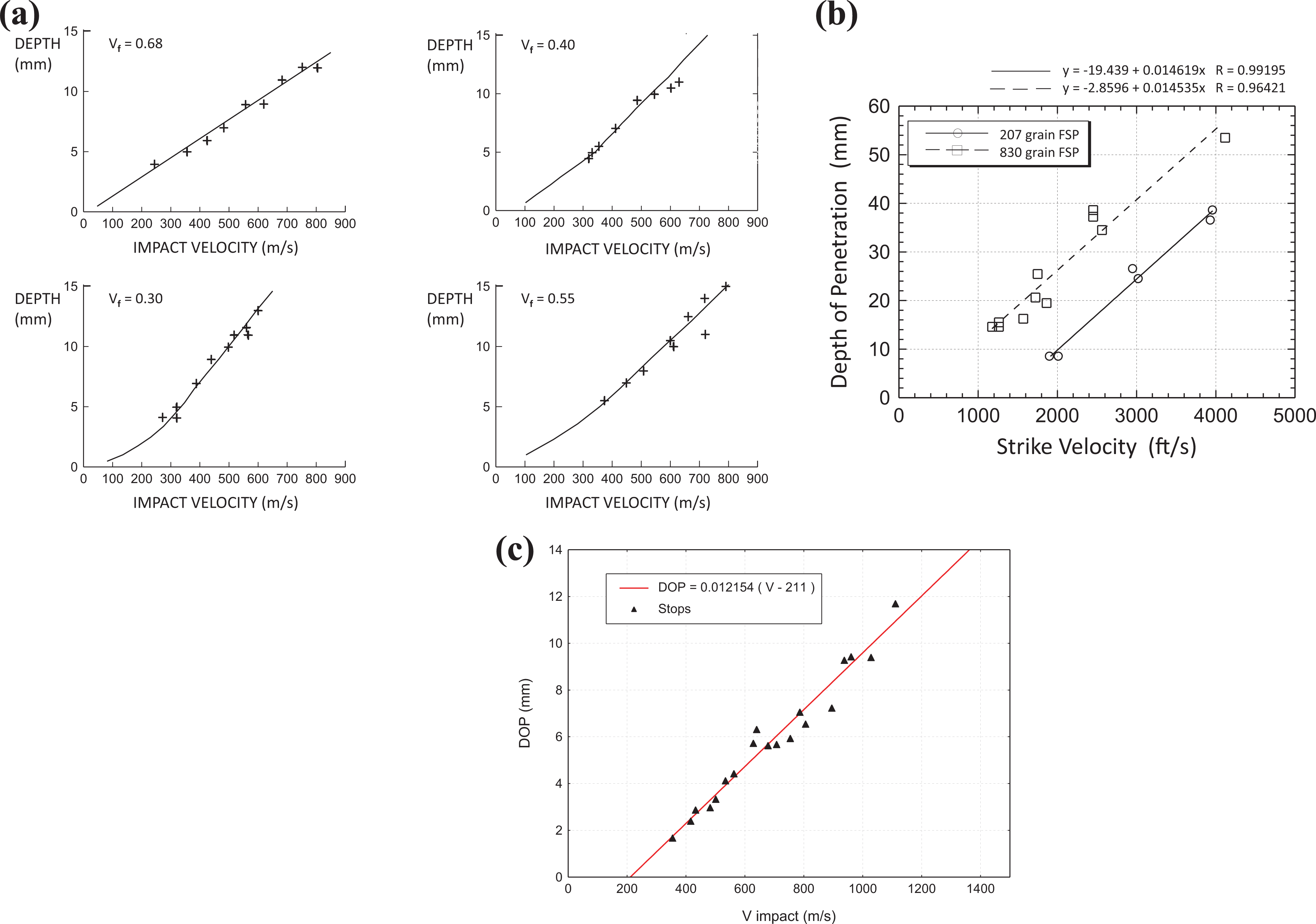
Penetration of projectiles into semi-infinite and finite thickness targets have been investigated in the past using experiments,1–8 modeling and simulation9–17 and by theoretical analysis18–22 Long rod penetration into metals, concrete and ceramics are common in literature, however, depth of penetration data on composites,23,24 is very limited. Figures 1(a) and (b) show the depth of penetration (DoP) experiments conducted by Greaves23 and Chou and DeLuca.24 These experiments were conducted with fragment simulating projectiles (FSPs, with length-to-diameter ratio close to 1) impacting thick composite plates supported by thick steel plates. This type of experiment is generally known as a penetration resistance test. In these experiments, two parameters are measured: (i) the penetration depth dP and (ii) the impact velocity of the projectile,VI. In Figure 1(a) and (b), the penetration depth is plotted as a function of the impact velocity, with trend lines that appear to be linear. In Ref.,25 depth of penetration (DoP) is measured from the ballistic limit (V50) experiments (not supported on the back face) on HB26® thick laminates. The authors present DoP as a function of impact velocity (V), and this also shows a linear relationship (Figure 1(c)). While there are a handful of penetration theories for very high velocity impact applications (e.g., Tate Theory,18,22 Cavity Expansion Theory26–28 and others in Refs.,17,29,30), no theories have been developed or used to analyze these classic DoP experimental data on composites with low aspect ratio projectiles.
Classic depth of penetration experiments on composites. (a) E-Glass/polyester impacted with 44-grain 0.30 cal FSP (2.851 g), fiber volume fraction, . (b) S-2 Glass/Cycom 4102 polyester, fiber weight fraction, , impacted with 0.50 cal (207 grain, 13.413 g) and 20-mm (830 grain, 58.783 g) fsps. (Reproduced with close resemblance to original figures in Ref.23,24) (c) reproduced from figure24 of Ref.25 with permission, DOP from unsupported ballistic experiments, HB26® ballistic laminate, areal density AD = 12.5 , thickness H = 12.9 mm, projectile: 5.54 mm diameter stainless steel sphere with mass g (10.8 grain), best fit equation: .
These classic DoP experiments on composites and ballistic experiments on HB26 inspired the present DoP experiments on thick-section Dyneema® HB26 hard ballistic laminates made from Dyneema® SK76 fibers and polyurethane (PU) matrix, which is a ballistic material of choice for personnel protection31–42 The main objectives of the present study are to identify the important parameters of the Depth of Penetration (DoP) experiments on Dyneema® HB26 thick laminates, to develop a data reduction procedure for the experimental data, and to develop a simple penetration theory that agrees well with the linear penetration depth as a function of impact velocity observed in the classic DoP experiments on composites. To achieve these objectives, the DoP experimental technique will be described first followed by a data reduction methodology and a simple penetration equation based on an energy approach.
Depth of penetration experimental and analysis methodology
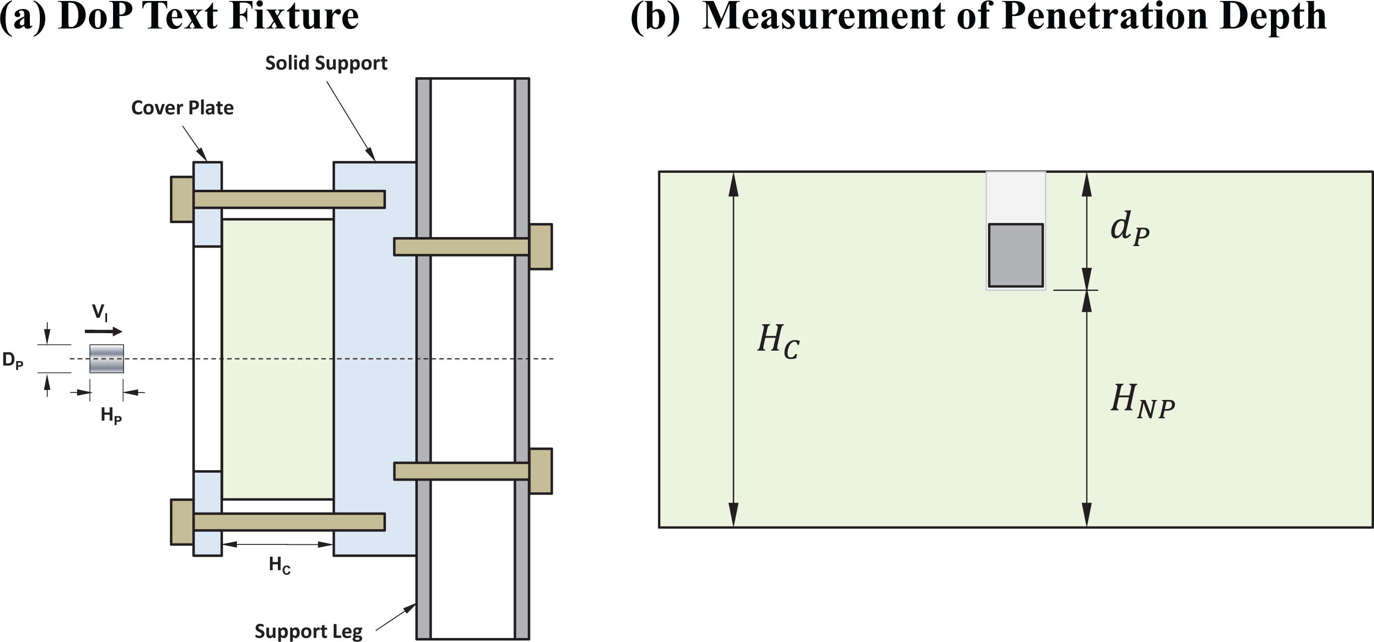
Penetration resistance of a material is usually quantified by conducting a depth of penetration experiment (DoP). In a DoP experiment Figure 2), a finite thickness target of thickness HC is clamped on a rigid support (on another support structure) such that the target thickness can be assumed semi-infinite. Upon impact, the projectile penetrates into the target and stops inside at a penetration depth of dP. In a DoP experiment, the penetration depths are measured and plotted as a function of corresponding impact velocities (VI) of the projectiles, which defines the penetration resistance of the target material as shown in Figure 1. From the linear plot of , one can immediately determine the slope of the curve, , which has a unit of time and can be defined as the characteristic time of penetration, . It is obvious that the characteristic time of penetration, , is an indicator of the penetration resistance of a target-projectile pair. A lower value of indicates a higher penetration resistance, while a higher value of indicates a lower penetration resistance. An energy-based analysis methodology is developed to provide better insight to the DoP process, and is presented next.
DOP experimental methodology.
Energy based analysis method for DoP experimental data
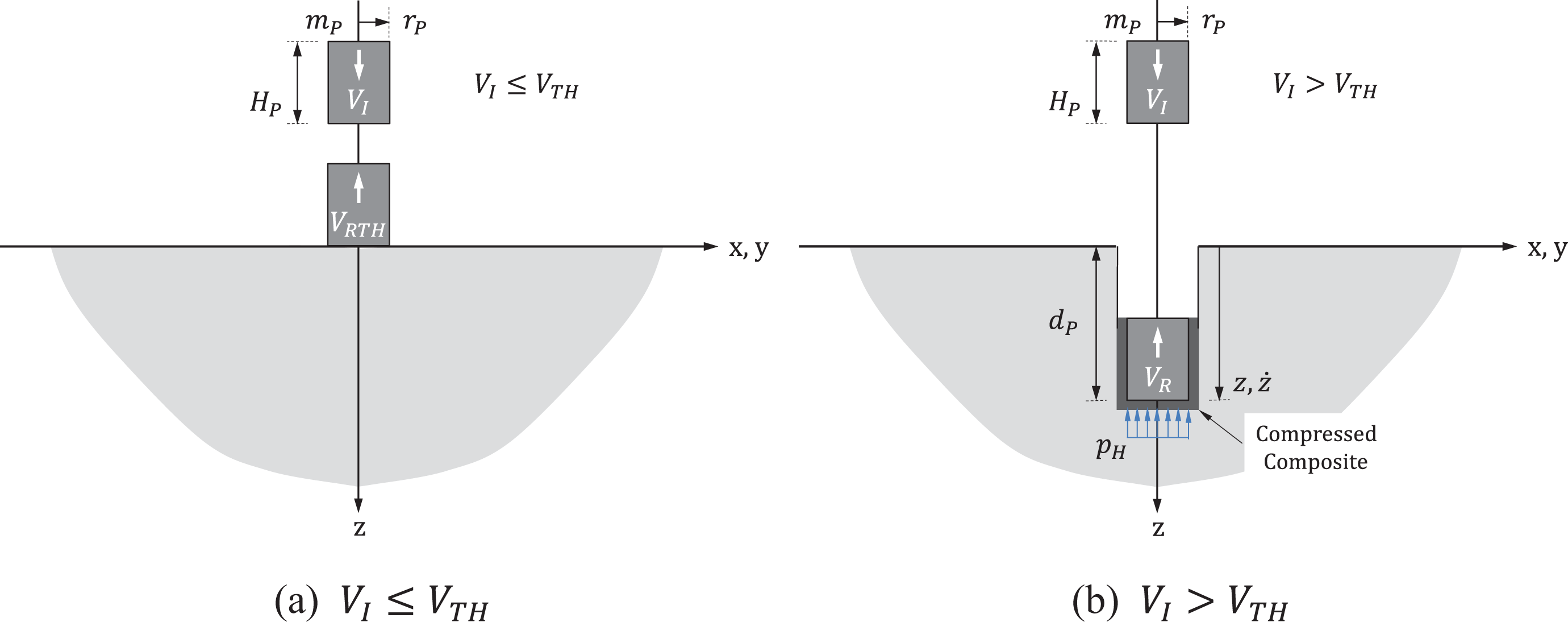
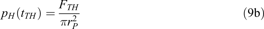
Consider a rigid, flat-nosed right circular cylinder (RCC) projectile, with radius rP, height HP, and mass mP, impacting a semi-infinite target at an impact velocity VI. Also consider a threshold impact velocity, , below which the projectile will not penetrate but rebound from the target with a rebound velocity , in a direction opposite to the impact velocity. The magnitude of is governed by the through-thickness (TT) stiffness of the target (Figure 3(a)). For an impact velocity greater than the threshold velocity, , the projectile will penetrate to a depth of dP (“P” is used for penetration depth in earlier penetration theories) after which the projectile will come to a complete stop and then rebound with a velocity VR (Figure 3(b)). Thus, one can conclude that the penetration of the projectile into the target will cease when the instantaneous velocity of the projectile, , equals the threshold velocity of penetration, i.e. . During the penetration process, an instantaneous penetration resistance force acts on the projectile. This penetration resistance force is defined as , where (where, is the TT stiffness, and is the TT strain in a composite target) is the hydrodynamic pressure of the highly compressed composite material in contact with and under the penetrating projectile (Figure 3(b)). For an uniform material through the thickness, the penetration resistance force is assumed to be linear with penetration depth . If the TT stiffness is a function of TT location z, i.e. , then an incremental linear approximation shall be used in a computational analysis method in calculating instantaneous penetration depth . For simplicity, in obtaining a closed form analytical solution, TT stiffness is assumed to the constant through the thickness of the target. For projectiles with different nose shapes than RCC, will not be uniform however can be estimated from Ref.,21,43–47 Since the projectile cannot penetrate the target below or at , is a material parameter of the target and can be determined from DoP experiments.
Fundamental concept of depth of penetration experiments.
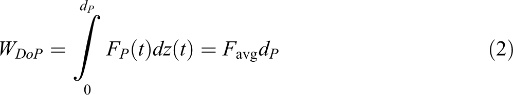
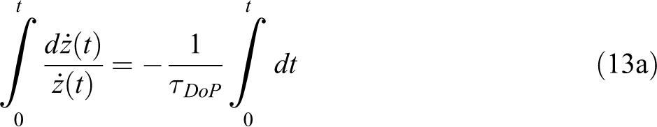
Following the principle of work and energy, from the time of impact () to the end of the penetration process (), when the projectile reaches the threshold velocity of penetration, the work of penetration () can be expressed as
where the impact energy is EI, and the kinetic energy at threshold impact velocity is . The work of penetration can also be expressed as
where the instantaneous location of the projectile and the instantaneous penetration resistance force acting on the projectile are given by and , respectively, and is the integrated average penetration resistance force defined as
where is the integrated average acceleration of the projectile. Using equations (1) and (3), we can express in terms of VI, , and dP,
where, is defined as,, is the characteristic time, is the initial deceleration at time , and is the final deceleration at time .The characteristic time , is defined as:
or,
One can determine the characteristic time () and the threshold velocity of penetration () from DoP experimental data using equation (6). The unit of characteristic time, , can also be expressed as [], which signifies that the projectile will penetrate the target by mm per 1 km/s of differential impact velocity (i.e., ). Using equation (4), equation (3) can also be expressed as:
where,FI is the initial penetration resistance force at , and is the threshold penetration resistance force at ; which can be expressed as:
where, is the damping coefficient (with the unit of or ) of DoP experiments.
Equations (1) to (8) are derived from the principle of work and energy and will be used to analyze the DoP experimental data (dP and VI) in calculating different DoP parameters, i.e. (i) the threshold velocity of penetration , (ii) the characteristic time , (iii) the initial penetration resistance force FI and the characteristic DoP damping coefficient , and (iv) the threshold penetration resistance force .
DOP experiments on Dyneema® hb26 hard ballistic laminates
DoP experiments have been conducted on thick section Dyneema® HB26 hard ballistic laminates of nominal thickness as supplied by the Army Research Laboratory – Aberdeen Proving Ground (ARL-APG). A hot press compression molding has been used in fabricating the HB26 laminates from a stack of 98 layers of [0/90/0/90] HB26 hard ballistic sub-laminates. Hot press plates are heated to 150°F (66°C) while the load on the stack of 98 HB26 sub-laminates is set to 145 psi (10 bar ∼ 1 MPa). Once the core temperature of the sub-laminates reaches 140°F (60°C), the load is increased to 3000psi (207 bar ∼ 20.7 MPa) and the temperature set to 267°F (131°C). Pressure is maintained until core temperature reaches 257°F (125°C, maximum allowed core temperature is 131°C). Laminates are cooled when core temperature reaches 257°F (125°C) and the HB26 laminate is unloaded when core temperature drops below 140°F (60°C).The processing temperature of HB26 laminates are limited by the melting temperature of UHMWPE crystals, 151°C155°C and the processing pressure has a significant effect on dynamic deflection.48 A high-pressure water jet has been used in preparing DoP specimens. Two specimens are stacked together and clamped between the bottom plate and the cover plate as shown in Figure 2(a).
A 16 grain, right circular cylinder (RCC, Figure 4(a)) and a 0.30 cal, 44 grain fragment simulating projectile (FSP, Figure 4(b))49 have been used in the present experiments. Following the range of projectile impact velocities presented in Figure 1, the present impact velocities have been varied in the range 400 m/s 1600 m/s in conducting all DoP experiments at Survice Engineering Company’s ballistic testing facility in Belcamp, MD. DoP targets are recovered after the experiments and are sectioned using a band saw and soaked in an ink-alcohol solution to apply optical contrast for photography. The non-penetrating distance is measured using a Vernier caliper to determine the depth of penetration dP by subtracting from the total thickness HC as shown in Figure 2(b).
Geometric properties of RCC and FSP projectiles, .
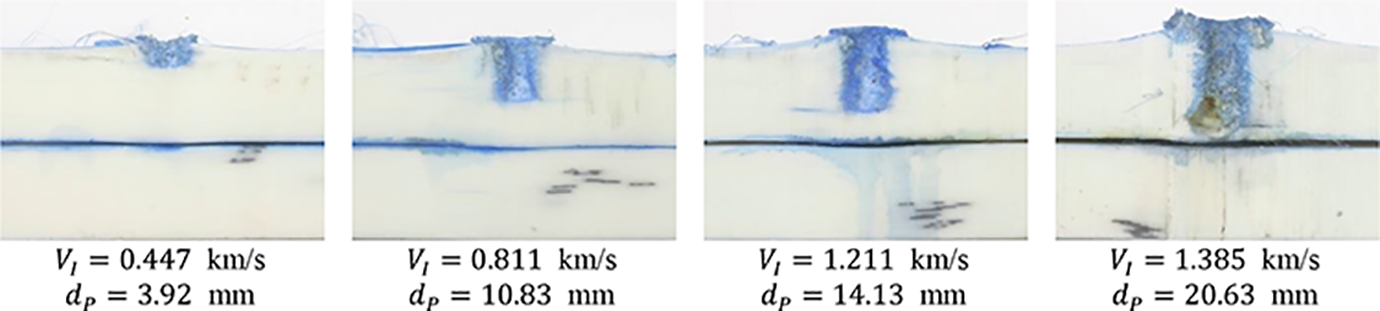
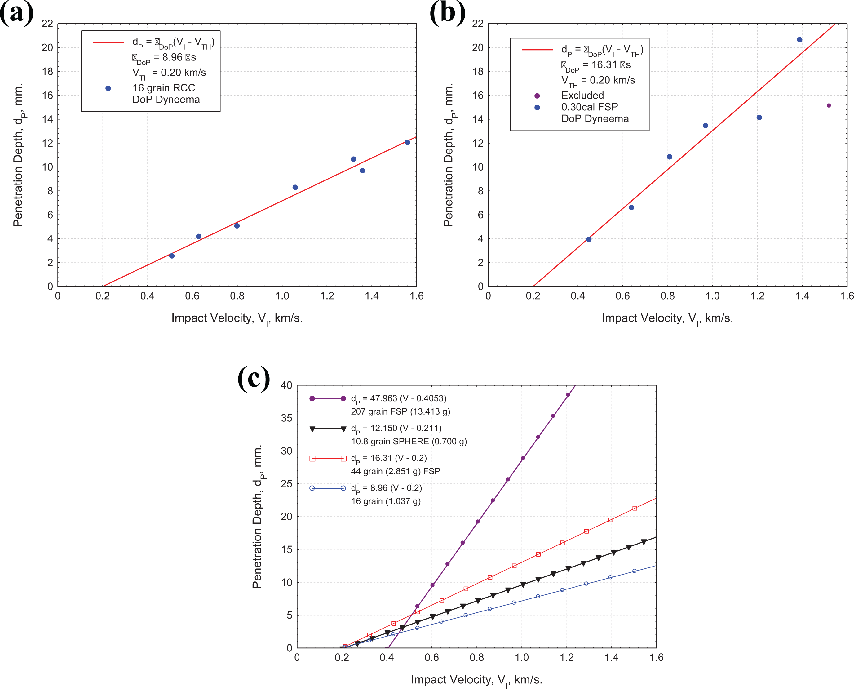
Selected cross-sections of the DoP specimens impacted with 16 grain RCCs and 0.30 cal 44 grain FSPs are presented in Figures 5 and 6, respectively. Penetration of projectile as a function of impact velocity appears as a cavity in the top target plate with significant bulging of the impact face and the rear face for impact velocities exceeding 1 km/s. Penetration depths (dP) of DoP targets as a function of impact velocities (VI) are presented in Figure 7(a) for 16 grain (1.037 g) RCCs, and in Figure 7(b) for 0.30 cal 44 grain (2.851 g) FSPs. A linear regression curve fitting methodology using equation (6) has been used to fit the experimental data in determining the value of threshold impact velocity () and characteristic time () for both the projectile-target pairs. The threshold velocity of penetration is found to be m/s for both the projectiles (a mere coincidence); however, the characteristic time is found to be 8.96 microseconds (or mm/(km/s)) for the 16 grain RCC and 16.31 microseconds (or mm/(km/s)) for the 0.30 cal 44 grain FSP. The effect of projectile nose shape and projectile mass may have effects on DoP parameters, and , which is beyond the scope of this paper. It is important to note that in Ref.,25 the threshold velocity of penetration and characteristic time for a 5.54 mm sphere of mass 0.7 g (10.8 grain) impacting an unsupported HB26® laminate of thickness 12.9 mm has been reported to be m/s and , respectively. Later we will show that unsupported DoP parameters (measured from V50 experiments) are significantly different than supported DoP parameters as they very different back face support conditions.
Selected cross-sections of DoP specimens impacted by 16 grain RCCs.
Selected cross-sections of DoP specimens impacted by 0.30 cal 44 grain FSPs.
Penetration depth of Dyneema® HB26 hard ballistic laminates as a function of impact velocity for (a) 16 grain RCC, and (b) 0.30 cal 44 grain FSP projectiles. Threshold velocity of penetration, km/s = 200 m/s. (c) parametric plot of equation (6) for different values of characteristic time, , and different projectiles.
Figure 7(a) and (b) shows that penetration depth at an impact velocity 1 km/s for 16 grain (1.037 g) RCC is 7.15 mm and for the 0.30 cal 44 grain (2.851 g) FSP is 13.00 mm. This difference in penetration depth at a constant velocity is due to difference in projectile mass, and the projectile nose shape (study of the effect of nose shape is outside the scope of this paper).
Figure 7(c) shows the plots of equation (6) for the present 16 grain (1.037 g) RCC and 44 grain (2.851 g) FSP experiments on HB26 compared with the 10.8 grain (0.700 g) Sphere unsupported V50 experiments on HB26 (van der Werff and Heisserer25), and 207 grain (13.413 g) FSP experiments on S-2 Glass/Cycom 4102 Polyester composites (Chou and DeLuca24). The effect of different projectile shapes and masses will remain as future experimental and computational tasks.
One data point of 0.30 cal FSP at km/s is excluded from all calculation as it is thought to be an outlier [possibly due to the high yaw]. The DoP data presented in Figure 7(a) and (b) appears to be linear and thus the use of energy based linear equation (6) is justified. With the known value of m/s and using each DoP experimental data point, the experimental characteristic time (equation (5)), impact decelerations aI and (equation (4)), impact forces FI and (equation (8)), and impact energy EI can be calculated from individual DoP experimental data and are presented in Tables A.1 and A.2 in Appendix A.
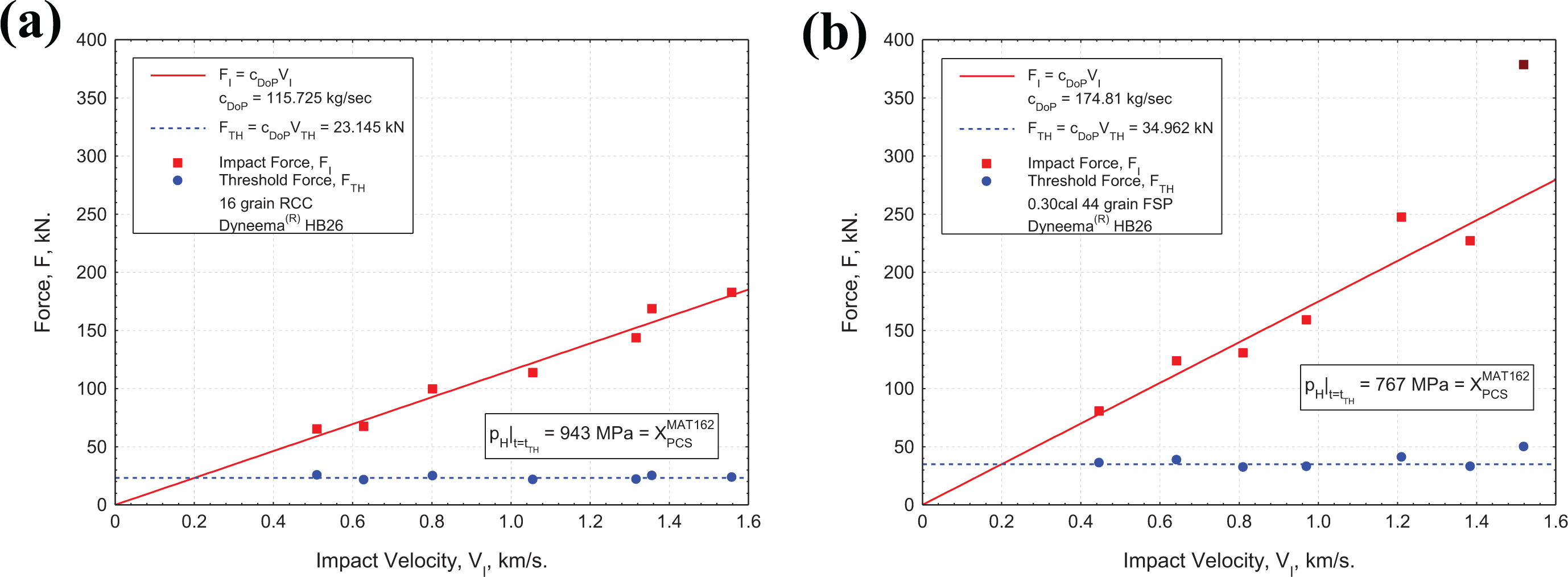
The calculated impact and threshold forces from Tables A.1 and A.2 in Appendix A are plotted in Figure 8(a) and (b) as a function of impact velocity. The impact force is linear with impact velocity as given by equation (8a) and the slope of the curve, , is the damping coefficient of DoP which is a constant for a target-projectile pair. Values of are calculated to be 115.73 kg/s or N/(m/s) for the 16 grain (1.037 g) RCC and 174.81 kg/s or N/(m/s) for the 0.30 cal 44 grain (2.851 g) FSP as shown in Figure 8(a) and (b). On the other hand, since is constant for both the projectiles, the average threshold forces have been calculated to be 23.15 kN for the 16 grain RCC and 34.96 kN for the 0.30 cal 44 grain FSP, respectively. Damping co-efficient for the 10.8 grain (0.700 g) sphere for HB26,25 and the 207 grain (13.413 g) FSP for S-2 Glass/Polyester24 have been calculated to be 57.61 N/(m/s) and 279.65 N/(m/s), respectively.
Impact force (FI) and threshold force () of Dyneema® HB26 hard ballistic laminates as a function of impact velocity for (a) 16 grain RCC, and (b) 0.30 cal 44 grain FSP projectiles. threshold velocity of penetration, km/s = 200 m/s.
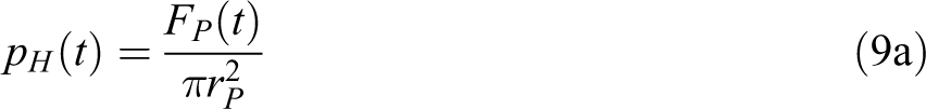
The instantaneous hydrodynamic pressure, , under the projectile can be calculated by dividing the instantaneous force by the cross-sectional area of the projectile.
At the threshold impact velocity , the threshold hydrodynamic pressure can be written as:
Threshold hydrodynamic pressures, , for the 16 grain (1.0337 g) RCC and the 0.30 cal 44 grain (2.951 g) FSP have been calculated to be 943 MPa and 767 MPa, respectively (Figure 8), while the same for the 10.8 grain (0.700 g) sphere for HB26,25 and the 207 grain (13.413 g) FSP for S-2 Glass/Polyester24 have been calculated to be 504 MPa and 887 MPa, respectively. The threshold hydrodynamic pressure, , for the 44 grain (2.851 g) FSP projectile is about 19% less than that of the 16 grain (1.037 g) RCC projectile for HB26, which is due to the truncated wedge shape of the FSP. The 16 grain (1.037 g) RCC value of the MPa for HB26 signifies that, if the through-thickness stress is less than 943 MPa, penetration will not occur.
where is the hydrodynamic pressure per unit impact velocity with the unit of or ; which have been calculated to be (i) 4.175 GPa/(km/s) for the 16 grain (1.037 g) RCC, and (ii) 3.833 GPa/(km/s)(19% less than RCC) for the 0.30 cal 44 grain (2.851 g) FSP projectile (iii) 2.319 GPa/(km/s) for the 10.8 grain (0.700 g) Sphere,25 and (iv) 2.189 GPa/(km/s) for the 207 grain (13.413 g) FSP24; respectively. This is a new, meaningful penetration resistance parameter, which tells what penetration resistance pressure or stress the target material will provide per unit impact velocity, and it can be directly calculated from the DoP experimental data. It is thus recommended to use RCC projectiles for DoP experiments in determining the penetration resistance parameters of the target plates, i.e. , , , &. Such experiments will provide information on the best-performing targets relative to the RCC projectile and this relative performance is expected to apply to other blunt projectile nose shapes.
Rigid body projectile dynamics during depth of penetration experiments
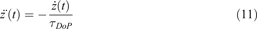
The energy based DoP data reduction methodology and the simple penetration model described by equations (1) to (10) have identified several DoP parameters, i.e. , , , & for a RCC projectile with rigid projectile assumptions. Using equation (4), a general equation for the instantaneous acceleration of the projectile can be written as
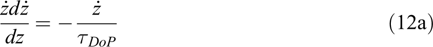
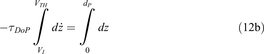
Equation (11) can be integrated to obtain the depth of penetration of the projectile as follows
Or,
Or,
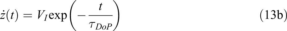
Equation (12c) is same as equation (6). The instantaneous velocity of the projectile can be determined as follows
Or,
Equation (13b) can further be integrated to obtain the instantaneous displacement of the projectile as
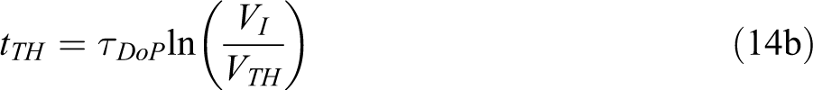
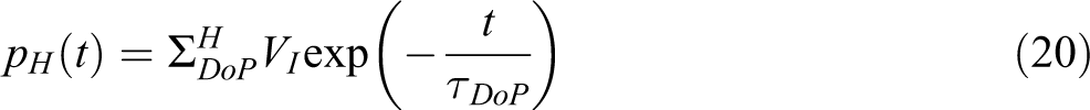
where, is the characteristic displacement of the projectile. At time , ; from which the threshold time of penetration can be expressed as
Substituting equation (13b) in equation (11) we can write
where, is the characteristic acceleration of the projectile. Then the penetration resistance force acting on the projectile is simply
where the is the initial impact contact force given by
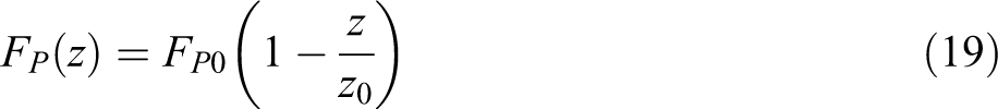
Penetration resistance force is a linear function of penetration depth and using equations (13) and (16) can be expressed as
Also, the instantaneous hydrodynamic pressure can be expressed as
Equations (11) to (20) describe the rigid body projectile dynamics which is valid until the threshold velocity of penetration,, when the penetration process ceases, however, the motion of projectile continues compressing the target material ahead of it. The rigid body projectile dynamics beyond is presented next.
Dynamic indentation of the rigid DOP projectile after the time of penetration
At time , the rigid body velocity of the projectile is . At this time, penetration of the rigid projectile into the composite ceases, however, the projectile continues to dynamically indent the target. A constant penetration resistance force is active on the projectile during the indentation period, and is given by
Thus for anytime , the equation of motion of the rigid projectile can then be expressed as
Then the velocity and displacement of the projectile are given by
and
Under constant deceleration during the dynamic indentation phase given by equation (22), the projectile velocity will be zero and rebound at time . Thus, from equation (23),
or,
where, is the total time of indentation phase.
Results and discussion
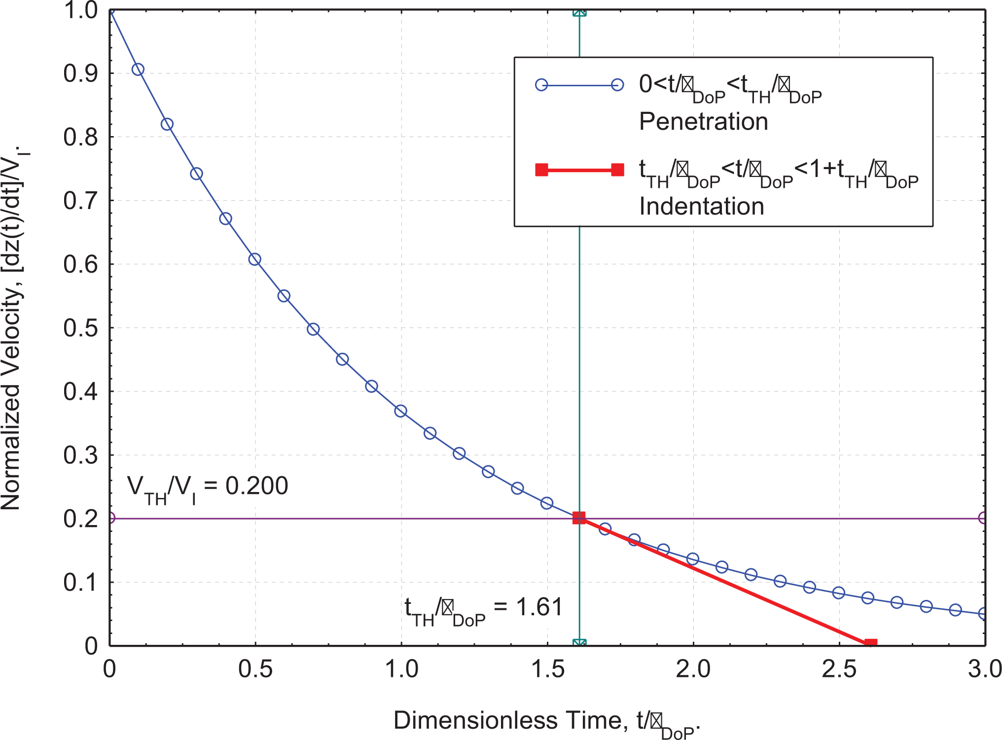
Dynamics of a rigid RCC projectile penetrating a target plate during a depth of penetration phase have been derived in equations (11) to (20). Projectile rigid body velocity (equation (12b)), penetration resistance force (equation (16)), and displacement (equation (13)) solutions are exponential in nature which are presented in Figure 9(a) in normalized form. On the other hand, the threshold time of penetration (equation (14)) is logarithmic and is presented in Figure 9(b). At the end of the penetration phase, projectile continues to indent the target, solutions for which have been derived in equations (21) to (25). Figure 10 shows the normalized indentation solution for a specific case with m/s and m/s. Equations (23) and (25) imply that the projectile velocity linearly reduces from to zero over the duration of indentation, .
Rigid body projectile dynamics during the DoP phase.
Rigid body projectile dynamics during the DoP and indentation phases. m/s, m/s, , , and .
Case study: Impact of a 16 grain (1.037 g) RCC Projectile on Dyneema® HB26 Target at km/s
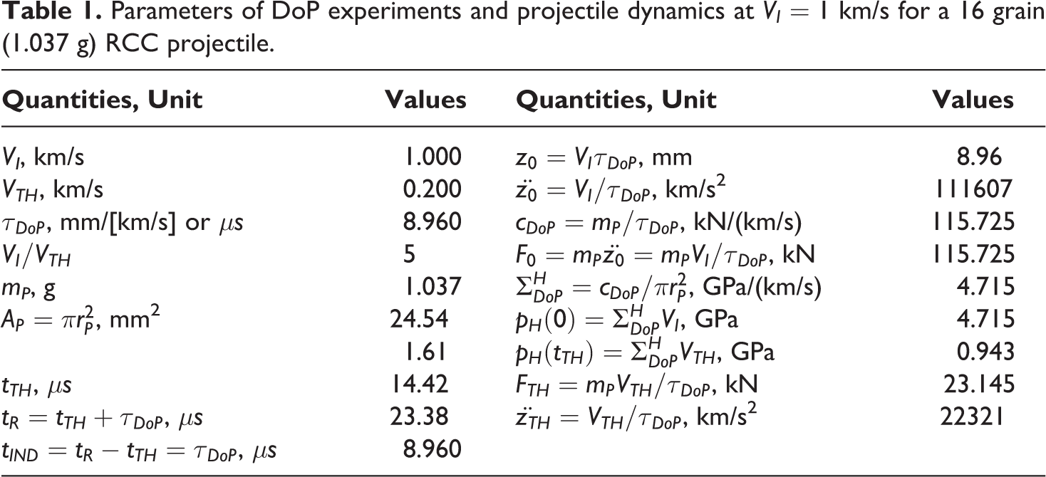
Parameters of DoP experiments on Dyneema® HB26 and projectile dynamics of a 16 grain (1.037 g) RCC for one impact case with km/s have been calculated and presented in Table 1, which also summarizes the experimental and analytical results. Two experimental DoP parameters m/s and characteristic time microseconds or mm/(km/s) signifies that penetration will not occur below an impact velocity of 200 m/s, and the RCC will penetrate the HB26 target by 8.96mm per 1km/s of differential speed (), i.e. with km/s, penetration depth will be mm. Threshold time signifies that the projectile will reduce its velocity from 1 km/s to 0.2 km/s in and will come to a stop in an additional . Damping coefficient is calculated from , which signifies that the initial impact contact force is 115.73 kN for km/s impact velocity, and the initial dynamic pressure is GPa. This is a very high pressure/stress, and requires the knowledge of Equation of State (EoS) for further analysis of the state of Dyneema® HB26 under extreme dynamic pressure. The limit stress/pressure of penetration is given by GPa, i.e. penetration damage will cease at this dynamic pressure/stress. DoP parameters for HB26 impacted with 0.30 cal 44 grain (2.851 g) FSP, and S-2 Glass/Polyester composites impacted with 0.50 cal 207 grain (13.413 g) FSP are compared to the HB26 impacted with 16 grain (1.037 g) RCC and is presented in Table B.1 in Appendix B.
Parameters of DoP experiments and projectile dynamics at km/s for a 16 grain (1.037 g) RCC projectile.
Quantities, Unit
Values
Quantities, Unit
Values
VI, km/s
1.000
, mm
8.96
, km/s
0.200
, km/s2
111607
, mm/[km/s] or
8.960
, kN/(km/s)
115.725
5
, kN
115.725
mP, g
1.037
, GPa/(km/s)
4.715
, mm2
24.54
, GPa
4.715
1.61
, GPa
0.943
,
14.42
, kN
23.145
,
23.38
, km/s2
22321
,
8.960
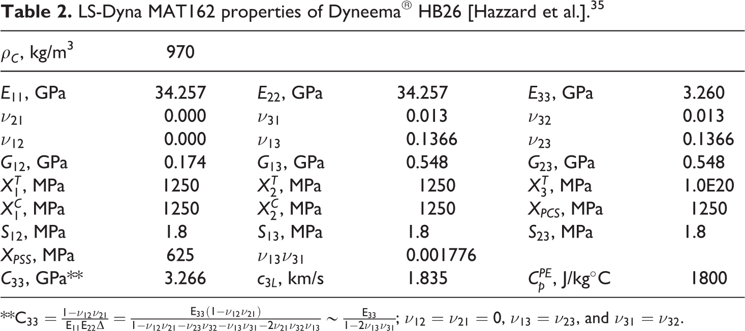
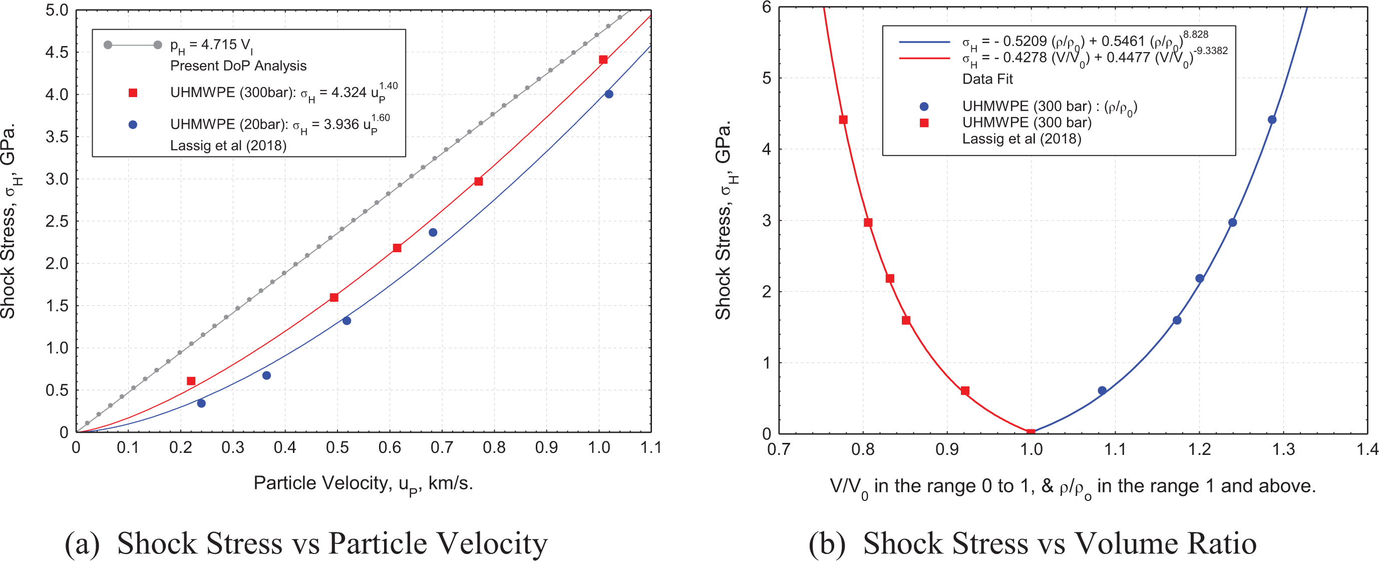
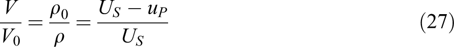
Table 2 shows the properties of Dyneema® HB26 laminate used in LS-Dyna progressive composite damage analysis under ballistic impact using MAT162 material model.35 The through-thickness modulus data from Table 2 can be used in calculating the longitudinal wave velocity of HB26 as km/s, where is the 33 component of the stiffness matrix. At an impact velocity of 1 km/s the dynamic pressure is 4.715 GPa, and an Equation of State is needed in calculating volumetric strains. Shock characteristics of UHMWPE have been recently presented by Lässig et al.41 at two different processing pressure, i.e. at 20 bar and at 300 bar. Shock stress () as a function of particle velocities (uP) are plotted in Figure 11(a) from the tabular data of Lassig et al. along with the best fit curves. Hydrodynamic pressure pH as a function of impact velocity (equation (10)) is also plotted on Figure 11(a) which appears as a straight line. Note that the rigid projectile assumption is simplistic and for this case, the particle velocity ahead of the projectile is assumed equal to the impact velocity. Present energy-based DoP model with two experimentally determined parameters (&) predicts a dynamic pressure well without the need for expensive plate impact experiments. Shock velocity (US) as a function of particle velocity (uP) is linear and have been calculated from Lassig et al. data as:
LS-Dyna MAT162 properties of Dyneema® HB26 [Hazzard et al.].35
where the first term on the right-hand side of equation (26) may equal to the longitudinal wave velocity . The volume ratio and density ratio are calculated using the shock relations:
The shock stresses for UHMWPE (300 bar) as a function of volume ratio have been plotted in Figure 11(b). Since the present Dyneema® HB26 laminate has been processed at 207 bar, and the longitudinal wave velocity is 1.835 km/s, the Lassig et al. data for UHMWPE (300 bar) closely resembles the present Dyneema® HB26 (207 bar) shock behavior.
From the pressure-volume ratio plot, it has been found that the volume ratio is (density ratio, ) for the shock stress of 4.715 GPa. Upon the RCC impact on the HB26 target at 1 km/s, the instantaneous dynamic pressure rises to 4.715 GPa, and the corresponding through-thickness volumetric strain is . The DoP penetration damage modes presented in Figures 5 and 6 show a penetration cavity with dynamic bulge at the impact face revealing that the highly pressurized cavity material is extruded from the cavity flowing out around the projectile and in a direction opposite to the projectile motion. The DoP damage mechanism is mostly unknown and remains a focus of our future work.
Conclusions
The following conclusions have been made from the present body of work.
DoP experiments should be conducted using a RCC projectile in order to determine DoP parameters such as threshold velocity of penetration , and the characteristic time of DoP .
A simple energy-based penetration model for DoP experiments has been developed which can reduce the DoP experimental data, and predict the rigid body projectile dynamics during the penetration and indentation phase.
The new DoP penetration model can calculate the initial impact force and dynamic pressure, and provides a new DoP parameter , which is the hydrodynamic pressure per unit impact velocity with the unit .
Footnotes
Acknowledgements
The authors are grateful to Mark Hazzard of DSM Dyneema for exchange of information and personal communication. Chris Meyer, a graduate student, was helpful in the discussion of penetration mechanics of hard ballistic soft laminates.
Funding
The author(s) disclosed receipt of the following financial support for the research, authorship, and/or publication of this article: Research was sponsored by the Army Research Laboratory and was accomplished under Cooperative Agreement Number 911NF-12-2-0022 and 911NF-13-2-0027. The views and conclusions contained in this document are those of the authors and should not be interpreted as representing the official policies, either expressed or implied, of the Army Research Laboratory or the U.S. Government. The U.S. Government is authorized to reproduce and distribute reprints for Government purposes notwithstanding any copyright notation herein.
References
1.
HauverGEMelaniA. Behavior of segmented rods during penetration. Adelphi, MD: Army Ballistic Research Lab Aberdeen Proving Ground, 1990.
2.
AndersonCEWalkerJDBlessSJ, et al.On the L/D effect for long-rod penetrators. Int J Impact Eng1996; 18(3): 247–264.
3.
ForrestalMJFrewDJHanchakSJ, et al.Penetration of grout and concrete targets with ogive-nose steel projectiles. Int J Impact Eng1996; 18(5): 465–476.
4.
RoachAEvansKJonesN.The penetration energy of sandwich panel elements under static and dynamic loading. Compos Struct1998; 8223(98): 119–134.
5.
FrewDJHanchakSJGreenML, et al.Forrestal. IJIEv.21i.61998; 21(6): 489–497.
6.
PiekutowskiAJForrestalMJPoormonKL, et al.Warren, penetration of 6061-T6511 aluminum targets by ogive-nose steel projectiles with striking velocities between 0.5 and 3.0 km/s. Int J Impact Eng2002; 23(1): 723–734.
7.
GomezJTShuklaA.Multiple impact penetration of semi-infinite concrete. Int J Impact Eng2001; 25(10): 965–979.
8.
MadhuVRamanjaneyuluKBalakrishna BhatT, et al.An experimental study of penetration resistance of ceramic armour subjected to projectile impact. Int J Impact Eng2006; 32(1–4): 337–350.
9.
ZukasJAJonasGH. “ARBRL-TR-02137 mechanics of penetration: analysis and experiment. Int J Eng Sci1979; 16(11): 879–903.
10.
LittlefieldDLAndersonJr CEPartomY, et al.Pergamon PII: SO734-743X(96)O0001-2 the penetration of steel targets finite in radial extent. Int J Impact Eng1997; 19(1): 49–62.
11.
AndersonCEOrphalDLFranzenRR, et al.Walker, on the hydrodynamic approximation for long-rod penetration. Int J Impact Eng1999; 22(1): 23–43.
12.
AndersonCEOrphalDL, An examination of deviations from hydrodynamic penetration theory. Int J Impact Eng2008; 35(12): 1386–1392.
13.
AndersonCEOrphalDL. Analysis of the terminal phase of penetration. Int J Impact Eng2003; 29(1–10): 69–80.
14.
WarrenTLFossumAFFrewDJ. Penetration into low-strength (23 MPa) concrete: target characterization and simulations. Int J Impact Eng2004; 30(5): 477–503.
15.
WalkerJD. Analytically modeling hypervelocity penetration of thick ceramic targets. Int J Impact Eng2003; 29(1–10): 747–755.
16.
AndersonCEChocronSBiggerRP. Time-resolved penetration into glass: experiments and computations. Int J Impact Eng2011; 38(8–9): 723–731.
17.
ChocronSAndersonCEWalkerJD, et al.A unified model for long-rod penetration in multiple metallic plates. Int J Impact Eng2003; 28(4): 391–411.
18.
TateA. A theory for the deceleration of long rods after impact. J Mech Phys Solids1967; 15(6): 387–399.
19.
ForrestalMJGradyDE. Penetration experiments for normal impact into geological targets. Int J Solids Struct1981; 18(3): 229–234.
20.
ForrestalMJFrewDJHickersonJP, et al.Penetration of concrete targets with deceleration-time measurements. Int J Impact Eng2003; 28(5): 479–497.
21.
ForrestalMJWarrenTL. Penetration equations for ogive-nose rods into aluminum targets. Int J Impact Eng2008; 35(8): 727–730.
22.
TateA. Further results in the theory of long rod penetration. J Mech Phys Solids1969; 17: 141–150.
23.
GreavesLJ. Failure mechanisms in glass fibre reinforced plastic armor. Memorandum 12/92, chertsey memorandum 92003. Chertsey: Defence Research Agency Military Division, 1992.
24.
ChouSCDelucaE. Dynamic response of S-2 glass reinforced plastic structural armor: a progress report. ARL-SR-5: AD-A273 868. Watertown, MA: US Army Research Laboratory, December1993.
25.
WerffHHeissererU. High performance ballistic fibres: ultra-high molecular weight polyethylene (UHMWPE). In: ChenX (eds) Advanced fibrous composite materials for ballistic protection. 1st ed, Chapter 3. Cambridge: Woodhead, 2016, pp. 71–108.
26.
SatapathySBlessS. Calculation of penetration resistance of brittle materials using spherical cavity expansion analysis. Mech Mater1996; 23(4): 323–330.
27.
SatapathySSBlessSJ. Cavity expansion resistance of brittle materials obeying a two-curve pressure-shear behavior. J Appl Phys2000; 88(7): 4004–4012.
28.
SatapathyS. Dynamic spherical cavity expansion in brittle ceramics. Int J Solids Struct2001; 38(32–33): 5833–5845.
29.
AndersonCE. Analytical models for penetration mechanics: a review. Int J Impact Eng2017; 108: 3–26.
30.
NguyenLHRyanSOrificiAC, et al.A penetration model for semi-infinite composite targets. Int J Impact Eng2020; 137: 103438.
31.
ChocronSKingNBiggerR, et al.Impacts and waves in Dyneema® HB80 Strips and laminates. J Appl Mech2013; 80(3): 031806.
32.
ChocronSNichollsAEBrillA, et al.Modeling unidirectional composites by bundling fibers into strips with experimental determination of shear and compression properties at high pressures. Compos Sci Technol2014; 101: 32–40.
33.
IannucciLDel RossoSCurtisPT, et al.Understanding the thickness effect on the tensile strength property of Dyneema®HB26 laminates. Materials (Basel)2018; 11(8): 1431.
34.
GreenhalghESBloodworthVMIannucciL, et al.Fractographic observations on Dyneema® composites under ballistic impact. Compos A Appl Sci Manuf2013; 44(1): 51–62.
35.
HazzardMKTraskRSHeissererU, et al.Finite element modelling of Dyneema® composites: from quasi-static rates to ballistic impact. Compos A Appl Sci Manuf2018; 115: 31–45.
36.
HazzardMKHallettSCurtisPT, et al.Effect of fibre orientation on the low velocity impact response of thin Dyneema® composite laminatesl. Int J Impact Eng2017; 100: 35–45.
37.
LässigTBagusatFPfändlerS, et al.Investigations on the spall and delamination behavior of UHMWPE composites. Compos Struct2017; 182: 590–597.
38.
LässigTNguyenLMayM, et al.A non-linear orthotropic hydrocode model for ultra-high molecular weight polyethylene in impact simulations. Int J Impact Eng2015; 75: 110–122.
39.
NguyenLHLässigTRRyanS, et al.A methodology for hydrocode analysis of ultra-high molecular weight polyethylene composite under ballistic impact. Compos A Appl Sci Manuf2016; 84: 224–235.
40.
NguyenLHLässigTRRyanS, et al.Numerical modelling of ultra-high molecular weight polyethylene composite under impact loading. Proced Eng2015; 103: 436–443.
41.
LässigTRMayMHeissererU, et al.Effect of consolidation pressure on the impact behavior of UHMWPE composites. Compos B Eng2018; 147: 47–55.
42.
ĆwikTKIannucciLCurtisP, et al.Investigation of the ballistic performance of ultra high molecular weight polyethylene composite panels. Compos Struct2016; 149: 197–212.
43.
AhmadiHEkramiMSabouriH, et al.Experimental and numerical investigation on the effect of projectile nose shape in low-velocity impact loading on fiber metal laminate panels. Proc Inst Mech Eng G J Aerosp Eng2019; 23310: 3665–3679.
44.
IqbalMAGuptaGDiwakarA, et al.Effect of projectile nose shape on the ballistic resistance of ductile targets. Eur J Mech A/Solids2010; 29(4): 683–694.
45.
GuptaNKIqbalMASekhonGS. Effect of projectile nose shape, impact velocity and target thickness on the deformation behavior of layered plates. Int J Impact Eng2008; 35(1): 37–60.
46.
GuptaNKIqbalMASekhonGS. Effect of projectile nose shape, impact velocity and target thickness on deformation behavior of aluminum plates. Int J Solids Struct2007; 44(10): 3411–3439.
47.
DeySBørvikTHopperstadOSLeinumJR, et al.The effect of target strength on the perforation of steel plates using three different projectile nose shapes. Int J Impact Eng2004; 30(8–9): 1005–1038.
48.
FejdyśMŁandwijtMKucharska-JastrzabekA, et al.The effect of processing conditions on the performance of UHMWPE-fibre reinforced polymer matrix composites. Fibres Text East Eur2016; 24(4): 112–120.
49.
MIL-DTL-46593Bdetail specification, projectile, calibers .22, .30, .50, and 20 mm fragment-simulating. 2008.