
Abstract
Determining the resistance to abrasion of the flexible cladding for armours and automobile structural components with the aid of lab scale tests has become increasingly important. In the present study, three body wear behaviour of flexible green composites comprising of jute in woven fabric form with interleaved natural rubber sheets bonded through rubberized B stage cured Pre pegs have been studied. Flexible composites are fabricated in three different configurations having different layers of jute and rubber. The present study makes use of silica sand as the abrasive medium. The specific wear rate along with loss in mass and volume of the composite due to wear is determined and it was found that specific wear rate is dependant of the sliding distance. Comparing the specific wear rate of all the three stacking sequences, it was found that JRJ stacking sequence provides better wear resistance. Compliant and tough nature of the rubber makes it hard to wear it out through tearing action and also the wear resistance of flexible composites is enhanced with inclusion of rubber. Mechanism of wear in each of the constituent used is studied. The present study serves as a benchmark work for the future research in this area.
Introduction
Thrust for newer class of materials is growing day by day. Composites have emerged as the potential materials in almost all fields of engineering. Most of the engineering components are subjected to one or the other type of wear during their entire service. 1 In almost all engineering applications, with an aim to reduce the weight and cost of the components, composites are being used as a replacement to metals and alloys. Polymer matrix composites are more prominently used compared to other types of composites.2,3 Due to the enormous advantages which composites with polymer base provides, polymers are extensively used in tribological applications 4 such as grinding mills, brakes, gears, transmission belts, lining and so on.3,5–7 Out of various types of wear the components are subjected to, abrasive wear is the most prominent one 8 caused by the hard chunk which move against the solid surface and forced against it. 7 The components made up of polymer matrix composites are subjected to three body abrasion during their working condition.
The material removal takes place when the hard asperities move across the surface resulting in formation of grooves. This mechanism is termed as abrasive wear. 9 The material removal mechanism can be by due to two body abrasion, three body abrasion or combination of both. Two body wear happens to occur is material removal operations where the abrasive particles are fixed and slides across the surface from where the material is removed, whereas in case of wear involving three bodies, the abrasives freely move relative to one another and may likewise pivot during sliding over the surface where wear happens. This kind of wear is more evident in engineering applications and finds a more prominent place compared to two body wear. Unfortunately, three body wear till now have received limited attention compared to two body wear. 10 It is found from the literature that though some amount of work is carried out pertaining to abrasive studies involving two bodies on the flexible composites,11,12 no studies are found related to abrasive studies involving three bodies. The mechanical characterization of the flexible composites carried out by few researchers showed that flexible composites exhibit excellent tear resistance. 13 Also, it was found that by using flexible matrix materials, the catastrophic failure of the components can be eliminated.14–17
Various researchers have reported the abrasive wear studies of different types of composites.18,19,20–28 Carbon reinforced polymer matrix composites was subjected to wear and its behaviour was studied. It was reported that volume loss of the composite is related directly to abrading distance and specific wear rate is related inversely to applied load and abrasion distance. It was also found that filler loading plays a prominent role in deciding the wear behaviour of the composite. 18 The other study carried out on polymer matrix composites 23 showed that addition of fillers in epoxy resulted in improved resistance against abrasion of the composite.
The three body wear behaviour of metal matrix composite and suggested that the material proposed can be used in wear resistant linings for handling large heavy abrasive ore particles, cylinder blocks, cylinder liners and brake disc. 20 The three body wear behaviour of 21 different materials was carried out and concluded that polyurethane has better has better abrasion resistance than the other materials considered. 10 The three body abrasive wear by (silica) sand of advanced polymeric coatings for tilting pad bearings was studied. 29
The careful study of literature referred above uncovers that there is a sufficient opportunity to comprehend and set up mechanism of wear pertaining to flexible composites subjected to wear under three bodies. The aim of the present work is to investigate the wear response of the natural fibre and elastomer-based flexible composite fabricated with three various stacking sequences. The mass loss is measured and volume losses, specific wear rate are computed and compared for all the three stacking sequences.
Experimental
Materials and methods
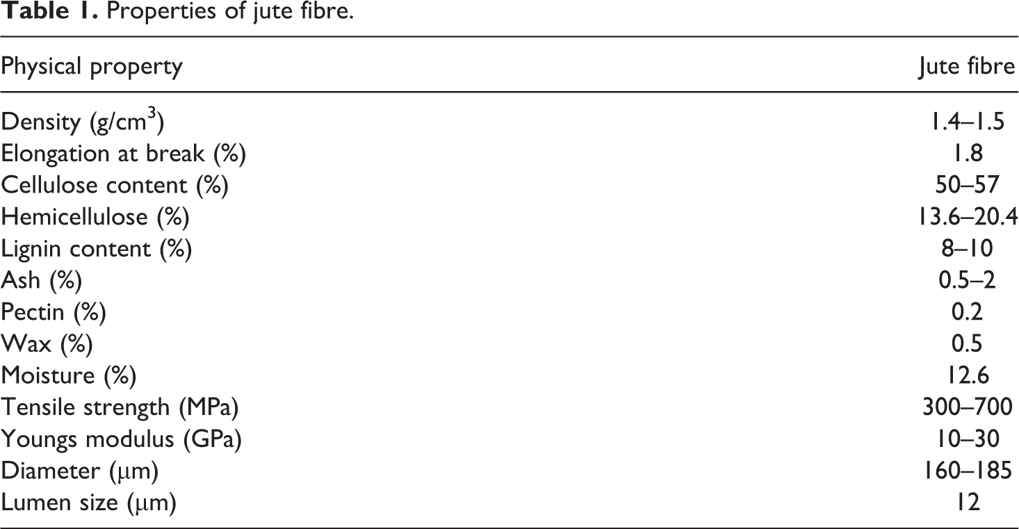
The woven fabric of jute (J) is used as reinforcement. Natural rubber sheet (R) is interleaved between the jute layers. The jute fabric and the rubber sheets are bound using natural rubber-based B stage cured pre peg which acts as matrix. Jute is procured from local market, natural rubber is supplied by the local suppliers of Belthangady, Dakshina Kannada district, Karnataka, India and the natural rubber-based B stage cured pre peg is procured from Manjunath Rubbers, Baikampady, Mangaluru, India. The properties of the jute fabric is provided in Table 1.
Properties of jute fibre.
The natural rubber (RSS Grade) exhibits mooney viscosity in the range of 68–90 units and contains 84% proteins and 16% lipids
Composites are processed using a compression moulding technique. The fabric and the rubber sheets are organized in the required stacking arrangement with natural rubber-based B stage cured pre peg between each layer. Complete set up is placed in middle of aluminium plates applied with high vaccum silicone gel that acts as releasing agent and kept in compression moulding machine at a temperature of 138°C for 7 min. After curing, the specimens of dimension 75 mm × 25 mm are cut from the cured laminates as shown in Figure 1.
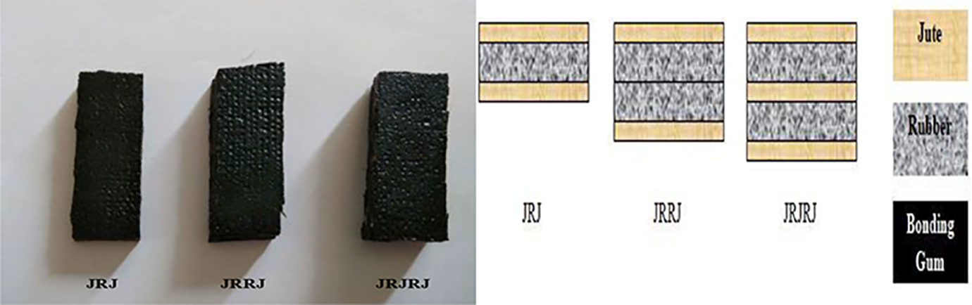
Specimens used for three body wear test.
Three body abrasive test
Figure 2 shows the schematic representation and the MAGNUM make test rig used to carry out wear test under three body condition.
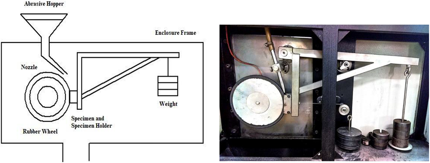
Schematic and MAGNUM three body wear test rig.
ASTM G 65 standard is followed to carry out three body abrasive wear test. The prepared abrasive samples are dry cleaned and their initial weight is measured using high precision digital balance before mounting on to the specimen holder. Silica sand of grade AFS 60 which are angular in shape with sharp edges are used as abrasive medium. The sand with its morphology is shown in Figure 3.
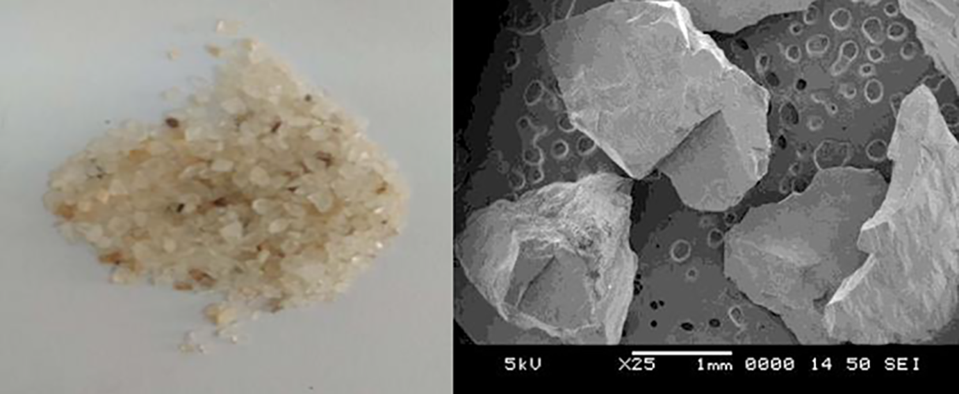
Silica sand used as abrasive medium.
The rotational speed of the rubber wheel is maintained constant at 150 rpm and the abrasive is fed in between the rubber wheel (comprising chlorobutyl rubber tyre with durometer shore A hardness of 58–60) and specimen. The specimen under test are made to press against the rotating wheel by applying load of 9.81 N with the help of lever arm, while controlled flow of abrasives, abrade the test surface. Finally at the end of test duration, the specimen is removed from the specimen holder and cleaned thoroughly before measuring its final weight. Weight loss of the specimen due to abrasion is determined using equation (1)

where, Ml,
The test conditions under which the tests are carried out are provided in Table 2.
Test conditions.
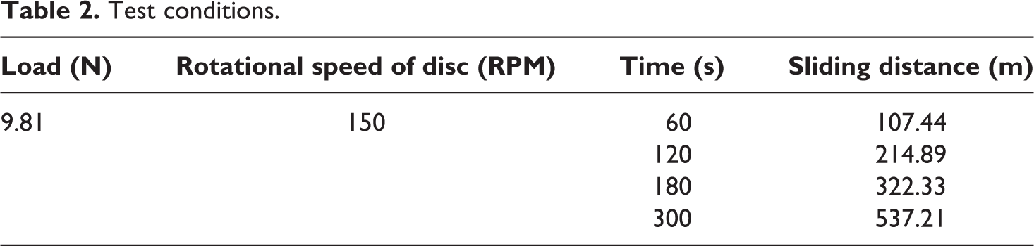
Three specimens of each configuration are tested and their mean values are used in the present study. The experiment was carried out with a sliding velocity of 1.79 m/s. Archimedes principle is made use of to determine the density of the proposed composites. The specific wear rate of the proposed composites in m3/Nm is calculated using equation (2)
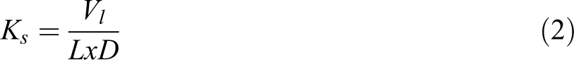
where Vl is loss of volume (m3), L is load applied (N) and D is distance of sliding (m). Equation (3) is made use of to determine the loss in volume of the composite.
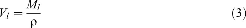
where ρ is density (g/m3).
Angular velocity of the rubber wheel in revolutions per minute is converted to linear velocity in metre per second using equation (4) and sliding distance is found using equation (5)

where V is linear velocity (m/s), r is the radius of the rubber wheel (m) and N is angular velocity of rubber wheel (RPM).

where T is time (S).
Surface morphology
After the wear test, a small portion of the worn surface is cut from the specimen and the nature of wear on the specimen is examined using Scanning Electron Microscope (JEOL JSM 6380LA) by depositing a thin layer of gold film on the surface to be examined.
Results and discussions
Volume loss and specific wear rate
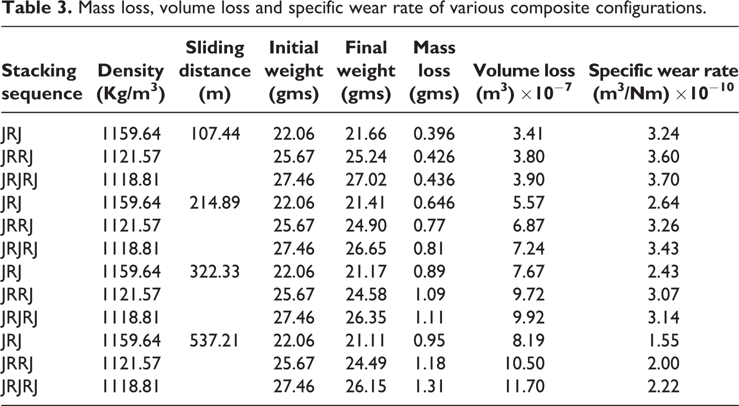
Table 3 provides the mass loss, volume loss and specific wear rate of different stacking sequences of flexible composites considered at different time duration/ sliding distance
Mass loss, volume loss and specific wear rate of various composite configurations.
The worn out samples with rubber and jute being exposed to the abrasive medium are shown in Figure 4.
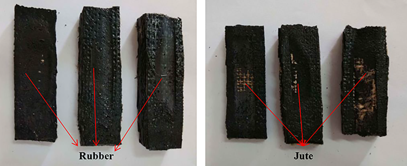
Worn out samples.
Figure 5 shows the variation of volume loss and specific wear rate of composites as a function of sliding distance. Observing the volume loss of composites, it can be justified that irrespective of the configuration of composite, the variation in volume loss of composite increases with the sliding distance linearly up to a sliding distance of 322.3 m. Further, the increase in volume loss changes its trend and slows down.
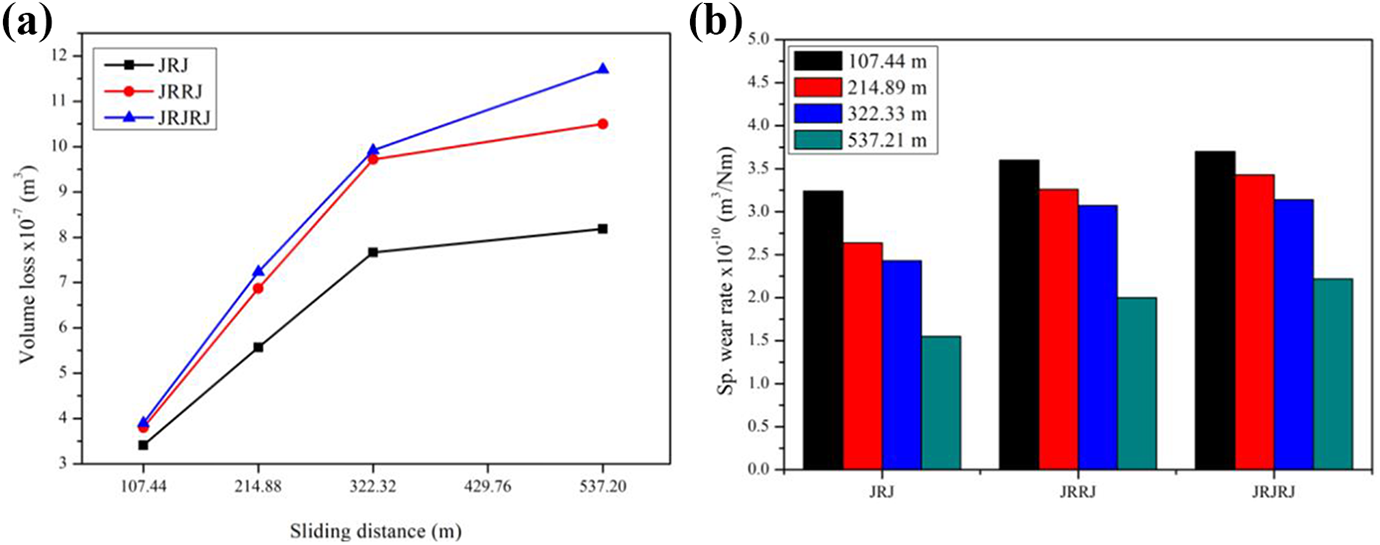
Variation of (a) loss of volume and (b) Specific wear rate of composites with respect to sliding distance.
Increase in volume loss is more when jute is exposed to the abrasive medium. This can be justified by the middle part of the graph (From sliding distance 214.89 m to 322.33 m) where the increase in volume loss is more rapid compared to later part of the graph (from 322.33 to 537.21 m) where the volume loss tends to slower down. This is due to the compliant and tough nature of the rubber which makes it hard to wear it out through tearing action. Thus the rubber can slow down the wear process. The variation in volume loss of JRRJ and JRJRJ are found to be negligible, whereas the volume loss of JRJ is found to be better than other two stacking sequences.
Observing the specific wear rate of all the three configurations, it is evident that JRJ exhibits lesser specific rate of wear compared to its counterparts. For the proposed composites with varied configurations used in the present study, the specific wear rate reduces with increase in sliding distance. This is due to the wear of jute fibre happening at the initial stage of wear process during which wear rate will be more and the rate of wear is minimized when rubber is exposed to abrasion. Compliant and tough nature of the rubber makes it hard to wear it out through tearing action.
Surface morphology
The surface morphology indicating different wear mechanisms of the exposed constituents during three body wear are presented in Figure 6(a) to (f). In general, an increase in the force or friction coefficient results in larger frictional force. This aids in fracture initiation on the surface of rubber further creating ridges. Then again, such expanded frictional power additionally relates to a progressively serious test, which implies that more energy will be discharged. This upgrades the effect of smearing, which works like ‘dissolving’ the ridge patterns into clingy elastic. They together decide the wear pattern.
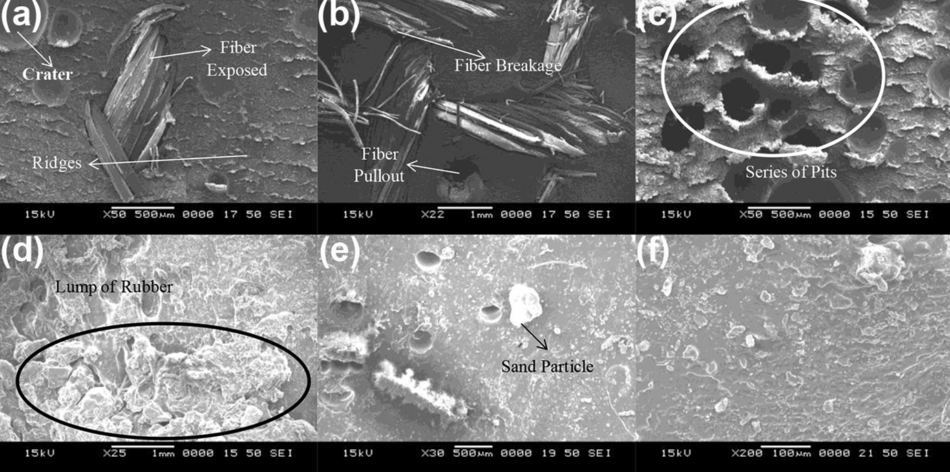
Surface morphology at different stages of wear. (a) Tearing of rubber; (b) Fiber pullout and breakage; (c) Void formation (d) Lump formation (e) Sand particle (f) Torn off lump from surface
Initially a thin layer of rubber-based gum is exposed to the abrasive medium where it under goes wear by the formation of tiny ridges and the sliding of sand on the rubber causes the crater on the surface of rubber by removing the portion of rubber due to tearing action as represented in Figure 6(a). Once the fibres are completely exposed to abrasive medium, the wear mechanism is dominated by breakage of fibres and fibre pullout results in creation of voids as shown in Figure 6(b). When all the fibres are removed from the matrix either due to fibre breakage or pull out, a series of pits or voids are formed on the rubber matrix (Figure 6(c)).
Further when the natural rubber sheet is exposed to the sharp abrasive medium, it gets attached to sharpness and gets stretched leading to development of crack. The ridges develop due to this mechanism and further they merge and grow to large pattern forming lumps of rubber (Figure 6(d)) and will be finally torn off from the sample surface (Figure 6(f)). This process may be associated to the fracture wear mechanism resulting in material loss.
Conclusions
In the present study, the three body wear behaviour of the different stacking sequences of green flexible composite are studied and the following conclusions are drawn: It is found that wear loss of the proposed composites depends on the sliding distance and the exposed constituent of the composite. The variation in volume loss of JRRJ and JRJRJ are found to be negligible, whereas the volume loss of JRJ is found to be better than other two stacking sequences. Volume loss is more when jute is exposed to the abrasive medium as opposed to rubber being exposed to abrasive medium. This is due to the compliant and tough nature of the rubber which makes it hard to wear it out through tearing action. Thus the rubber can slower down the wear process. Specific wear rate is strongly dependant on the sliding distance and the component being exposed to abrasive medium. Irrespective of the stacking sequence, it is found that the specific wear rate of flexible composite decreases with increase in sliding distance. JRJRJ has the highest and JRJ has the least specific wear rate and it is found that JRJ has highest wear resistance among all the other configurations considered in the present study. It is found that specific wear rate of a flexible composite can be reduced by inclusion of rubber. Rubber being a tough and compliant material is found to be suitable for use as a constituent in composites intended to be used for cladding application subjected to wear.