
Abstract
Polyether-ether-ketone (PEEK) has been proposed as a biocompatible artificial joint material. Wear particles, generated by friction between artificial joints, lead to bone resorption, aseptic loosening, and ultimately, joint failure. The size and morphology of wear particles contain information of friction and wear. Aim to obtain the wear mechanism of PEEK under different loads, this study separated PEEK debris and investigated the mechanism of wear debris and the relationship between wear mechanism and PEEK-debris morphology. An experiment was carried out with a pin-on-plate testing apparatus under different load conditions, with PEEK sliding against XLPE under saline lubrication. A method of isolating PEEK and XLPE debris from 0.9% normal saline at the same time was investigated by low-speed centrifugation. The morphologies of worn surface and wear debris were obtained based on scanning electron microscopy. The results showed that the maximum friction coefficient and minimum wear loss were 0.115 and 0.223 mg at the load of 50 N. The friction coefficient decreased and the wear loss increased with the load increase. This debris-isolation method can effectively isolate PEEK and XLPE particles larger than 200 nm in diameter. More than 96% wear PEEK particles range from 0.1 µm to 10 μm. Compared with the debris generated under the lower load condition, 0.8% more large wear particles with irregular shapes were found at a load of 150 N. The morphology of wear particles is consistent with the wear mechanism.
Introduction
Polyether-ether-ketone (PEEK) is a half-crystalline thermoplastic polymer with low elastic modulus, high strength, high wear resistance, and good biocompatibility. PEEK has been increasingly employed as an effective biomaterial for implantable medical devices such as orthopedic, spinal, and cranial implants, and has been considered as a promising artificial joint material.1–3
Traditional artificial joint materials are CoCrMo-on-UHMWPE, Matel-on-Matel, and ceramics-on-ceramics.4–6 The ions produced by CoCrMo decomposition are harmful to bone and muscle tissue. Poor resistance to impact of ceramics and poor abrasion resistance of Titanium alloy shorten the serving time of prostheses. Compared with metal and ceramic, PEEK particles have been recognized as non-cytotoxic. 7 However, there are different opinions on the release of inflammatory factors, which requires further research. 8 PEEK is a new artificial joint material with more similar elastic modulus to natural bone compared with traditional materials. 9 PEEK and cross-linked polyethylene (XLPE) are thermoplastic/thermosetting polymer combinations with strong hydrophilicity, remarkable wear performance, and adhesive-abrasion resistance.
Wear particles generated from the friction of the joint prosthesis in vivo may lead to toxicities, immune reactions, bone resorptions, aseptic loosening, allergies, and local tumors, which is a worldwide problem and has been named wear particle disease. This shortens the service life of prostheses.10–13 It has been shown that these diseases are related to factors such as size, quantity, and morphology of wear particles. 14 Shanbhag et al. 15 reported that particles with diameters less than 10 µm were easily ingested by phagocytes, and had strong biological activity. A study by Green et al. 16 suggested that most biologically active polyethylene particles had a size range from 0.3 µm to 10 μm. The isolation and characterization of wear particles are important for investigations by domestic and overseas experts. The characterization of wear particles requires on an appropriate isolation protocol. 13 Much research focused on the isolation of artificial joint wear particles from the lubricating medium. Affatato et al. 17 proposed a method to isolate ultra-high molecular weight polyethylene (UHMWPE) wear particles from the bovine calf serum in a low vacuum system. Galvin et al. 18 proposed a UHMWPE method with a multidirectional pin on a plate wear simulator against smooth and scratched counterfaces; the authors revealed the presence of nanometer-sized polyethylene wear particles for the first time. Jia et al. 19 showed that Ti6Al4 V particles in calf serum of a hip joint test machine could be effectively isolated with an ultrasonic wave.
Because of the large density difference between metal, ceramics, UHMWPE, and solvent, debris separation can be easily achieved. In artificial joint friction tests, previous studies on the separation of artificial joint wear particles mainly focused on metal ceramics and UHMWPE.20,21 PEEK is considered a promising artificial joint material and the density difference between PEEK and solvent is very small. However, methods of isolating PEEK wear particles have rarely been studied. Based on the traditional isolation method of metal debris, a novel method for isolating PEEK debris is proposed that utilizes its density. It is of great importance to isolate and analyze PEEK wear particles via wear tests in vitro.
This study conducted an experiment with a pin-on-plate testing apparatus under different load conditions, where PEEK slid against XLPE under saline lubrication. A method of separating PEEK wear particles from saline was introduced. The morphology, diameter, and size distribution of wear particles were identified. In addition, different wear mechanisms during the friction process were discussed, based on scanning electron microscopic (SEM) images. The relationship between the wear mechanism and the mechanism of wear debris was investigated.
Experimental and methods
Materials
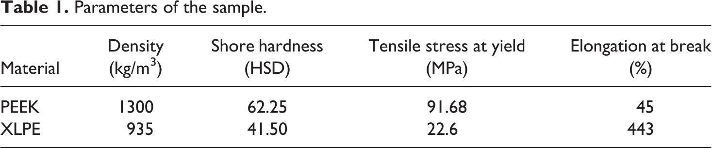
Pins were injection molded of PEEK powder (Jiangsu Oconee Medical Technology Development, Co., Ltd., Suzhou, China). XLPE was purchased from Quadrant China Ltd., Shanghai, China. Parameters of samples are shown in Table 1. All materials used in the test were medical biomaterials and were directly employed to the test without further modification. PEEK was machined into cylindrical pins with an overall dimensions of 12 mm in length and 4 mm in diameter, and XLPE plates were shaped to 33 mm in diameter and 5 mm in thickness for all tests. The PEEK and XLPE surfaces were ground and polished to an average roughness of Ra = 0.2–0.4 μm. Before testing, samples were soaked in 0.9% normal saline (NS) for 48 h to minimize the effects of fluid absorption, washed thoroughly in an ultrasonic cleaner, and dried for at least 30 min in a vacuum drying oven, strictly abiding to standard test protocols. 22
Parameters of the sample.
Friction test
Pin-On-Plate testing was carried out with a UMT-II tribometer, taking 0.9% NS as lubrication medium. The nominal loads of 50 N, 100 N, and 150 N were applied to the pins. At a load of 50 N, the stress was the equivalent of the normal stress of a human knee joint. The sliding distance is 5 mm (ISO14243-1, implants for surgery—wear of total knee-joint prostheses). All wear tests cycle frequencies were 1 Hz and the sliding time was 6 h.
Isolation of wear particles
Settling effect of particles in the lubricating medium
The settling of wear particles in suspension changes the density of the suspension. If the viscosity of particles decreases with increasing shear rate, the lubricating medium is a non-Newtonian fluid.21,23 However, small perturbance to the lubricating medium around particles resulted from small PEEK and XLPE wear particles. The calculation showed that the settling velocity of 5 µm diameter particles of PEEK in the 0.9% NS was about 0.12 mm per hour and that of 1 µm diameter particles is 0.005 mm. Therefore, the settling velocity of PEEK particles was very low as natural subsidence. A centrifugation method was applied to accelerate the particles in suspension rising or settlement. The settling velocity is directly proportional to the volume of particles and the relative centrifugal force in suspension. Therefore, the higher the centrifugal speed, the greater the settling velocity of particles in static suspensions. This study centrifuged the suspension in a centrifuge tube at a speed of 4000 r/min. The calculation result showed that 0.5-µm diameter PEEK particles settle about 2.5 cm when centrifuged for 10 h, which can obtain nanometer-scale particles of PEEK at the bottom of the centrifuge tube.
Isolation method of particles with different sizes
The wear particles of XLPE and PEEK in the NS float and sink, respectively, because of differences of relative density in the lubricating fluid to obtain particles of XLPE and PEEK in the NS after friction test, the separation procedures were as follows: firstly, transfer the lubricating fluid to a centrifuge tube after the test and dilute it with deionized water to two-thirds of the centrifuge tube. Secondly, centrifuge the mixture for 10 h at a rate of 4000 r/min to accelerate the floating and settlement of particles. Then, take the 2.5 ml top solution and the bottom solution, respectively. Thirdly, dilute and centrifuge the solution obtained in the previous step three times to avoid salt crystallization. Before filtering the solution with 0.22 µm pore diameter micropore membrane filters, dilute the top and bottom solution with 1000 ml deionized water to avoid salt crystallization. Filtering the dilute solution by a self-made device for the separation of micro and nanoparticles as shown in Figure 1. Ultrasonic waves can be used to inhibit the agglomeration of PEEK nanoparticles. Adjust the vacuum to retain a dropping speed of 1 drop/s.
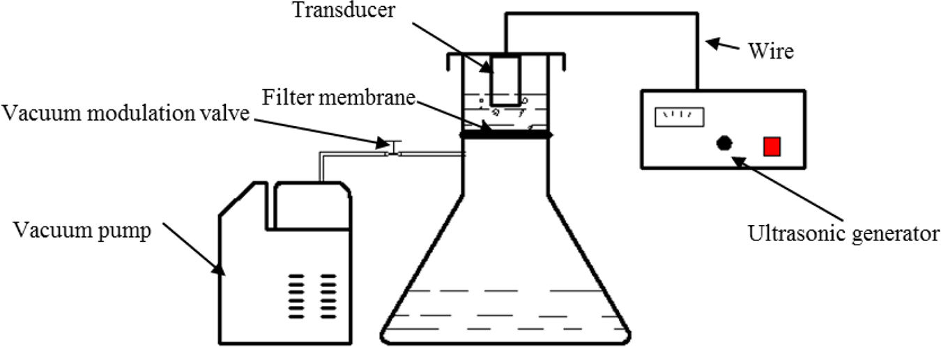
Filtration of the micro-nanometer particles separation system.
Verification of particle identity
Fourier transform infrared spectroscopic (FTIR) spectra were obtained to determine the identity of wear particles from samples using VERTEX 80v. Selected filter membranes with PEEK particles were measured before SEM. The wear particles collected in the friction test at a load of 150 N by the filter membrane were pressed into potassium bromide tablets to measure infrared absorption spectra.
Wear particles and worn surface imaging
After filtration, filters were dried in a vacuum drying oven before the PEEK particles on the filter membrane were observed with SEM. After gold spraying, images of both particles and worn surfaces of specimens were taken with a Quanta 250 microscope (FEI Quanta™ 250, MA, USA). The particles and worn surfaces were imaged with an accelerating voltage of 25 kV in high vacuum mode.
Results
Friction coefficient and wear loss
Figure 2 showed the variations of friction coefficients of PEEK-on-XLPE under different loads. The friction coefficient of PEEK-on-XLPE was small and stable. The friction of three groups reached the steady state after fluctuations in the running-in stage. The coefficient of friction was 0.115 when the normal load was 50 N. It decreased by 17% and 30% under loads of 100 N and 150 N, respectively. Wear loss increased as load increased under lubrication with normal saline. The wear losses were 0.223 mg and 0.25 mg at loads of 50 N and 100 N, respectively. When the normal load was 150 N, the wear loss increased sharply, and reached 0.36 mg (Figure 3).
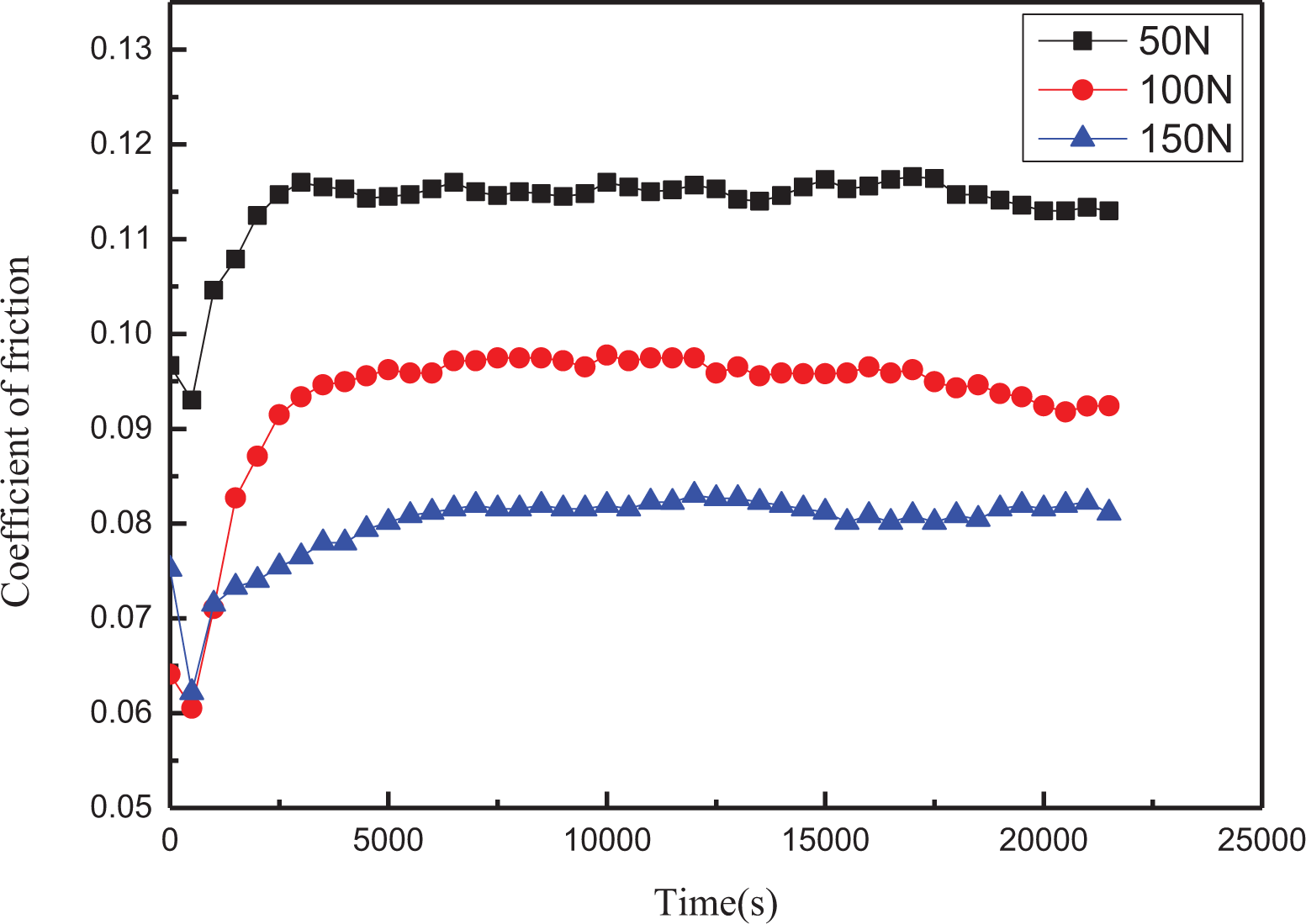
Friction coefficient as a function of sliding time under different load conditions.
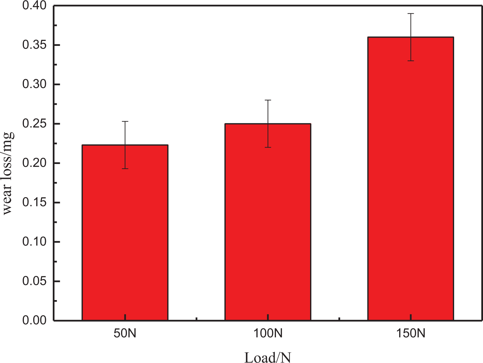
Wear loss of PEEK after wear test under different load conditions.
FTIR spectrum
The characteristic bands of particles (both non-isolated and isolated), eliminating the spectrum of the filter, were shown in Figure 4. The following absorption peaks were identified: 1150 cm−1 (C-H bending of benzene ring of aromatic ether ketone), 1160 cm−1 (etheric bending), 1599 cm−1 and 1490 cm−1 (C=C stretching of benzene ring) and 1650 cm−1 (aromatic ketone C=O). The FTIR spectrum for isolated PEEK debris was consistent with PEEK debris.
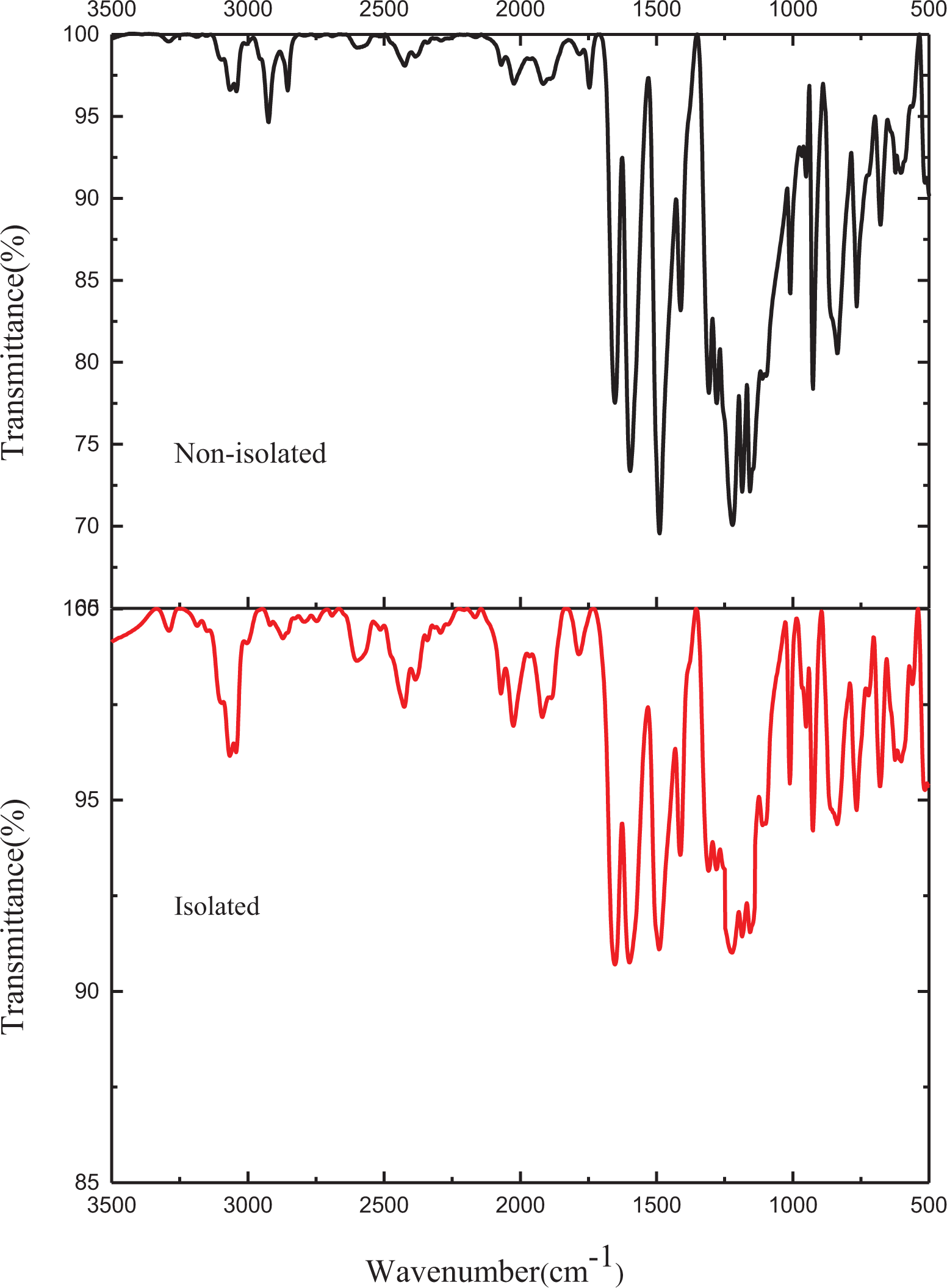
FTIR spectra of PEEK debris.
Figure 5 showed the FTIR spectra of non-isolated and isolated UHMWPE debris. Absorption bands at 2919, 2850, and 1064 cm−1 occur because of C-H stretching. Absorption peaks at 1460 and 719 cm−1 correlated to C-H bending and that at 1170 cm−1 corresponded to CH2 rocking. The FTIR spectrum for isolated XLPE debris was consistent with that of XLPE debris. The result shows that the method can be used to separate PEEK and XLPE particles from NS.
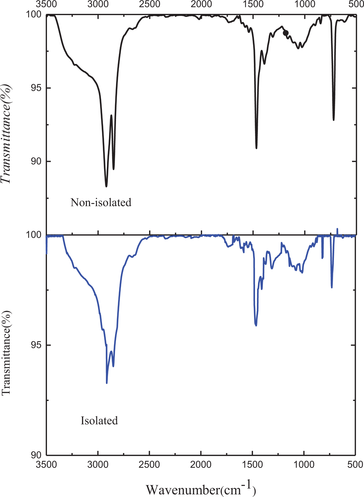
FTIR spectra of XLPE debris.
Wear particle size distribution
The particle size produced by friction varied considerably. Large particles contributed to wear loss, while small particles were the main factor that led to aseptic loosing. Figure 6 showed the percentage distribution of wear particle sizes under different load conditions. The distribution of particles agreed well and was relatively concentrated, more than 96% particles ranged from 0.1 µm to 10 μm, which was the same as in the XLPE in vitro wear test. These results were similar to those of a previous study. 4 The granularity distribution of PEEK particles was concentrated under loads of 50 N and 100 N. The maximal diameter of wear particles was about 20 µm at loads of 50 N and 100 N. At a load of 150 N, the granularity distribution of particles was more dispersed than that under other conditions, and the number of large wear particles clearly increased. The percentages of 10 µm to 20 µm and larger than 20 µm were 0.6% and 1.8%, respectively, which exceeded percentages under loads of 50 N and 100 N. The high quantity and proportion of large particles corresponded to the wear rate, as mentioned previously.
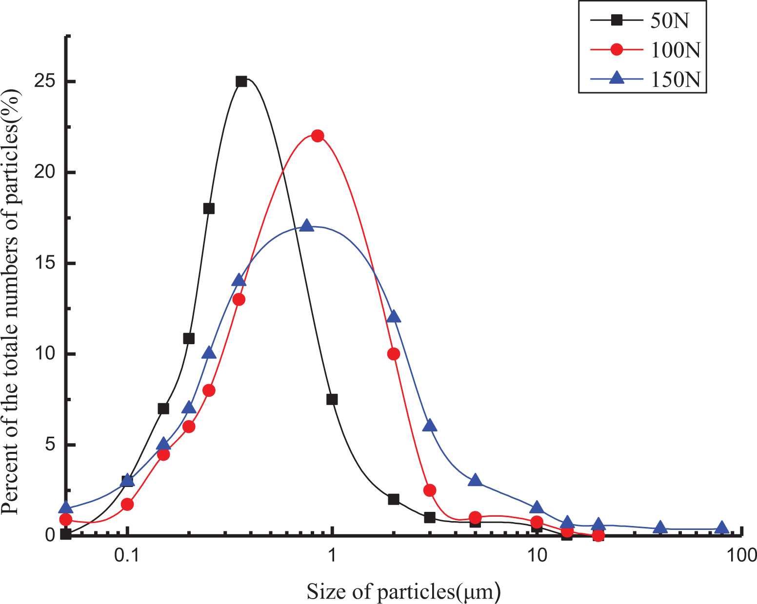
Wear particle size distribution under different load conditions.
Worn surface images of PEEK and XLPE
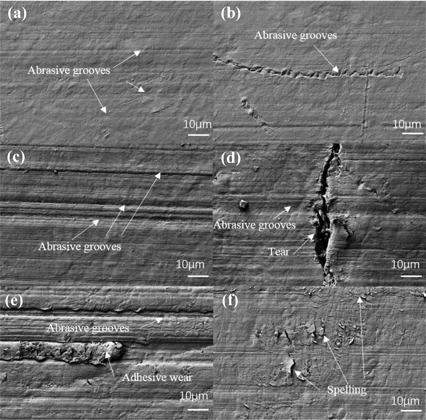
Figure 7 showed the worn surfaces of PEEK under different loads. Abrasive grooves and a large number of particles with sizes smaller than 1 micron were found on the wear surface under a load of 50 N. In particularly, a very small amount of block particles adhered to the wear surface. The wear mechanism under 50 N load was mainly micro-cutting (Figure 7a, b). Figure 7c showed that plow grooves were the main wear form under 100 N load, and a few pits emerged because of fatigue spalling. Large flaky XLPE particles adhered to the worn surface and formed a transfer film, which decreased the friction coefficient because of lubrication. The depth and width of the plow grooves increased slightly compared with that under 50 N load (Figure 7d). With increasing load, larger particles cut the surface of friction pairs. This was the reason for the larger wear loss of PEEK than that of under a load of 100 N. Figures 7e and f showed that the number of plow furrows increased. The depth and width increased sharply, and the edges of plow furrows were neat. Blocky particles of 5 microns adhered to the worn surface in Figure 7f. The large bar particles were generated by serious plow-grinding when the large abrasive particles penetrated the worn surface. The wear rate increased significantly under a load of 150 N. The wear mechanisms were consistent with the conclusions obtained via particle morphology.
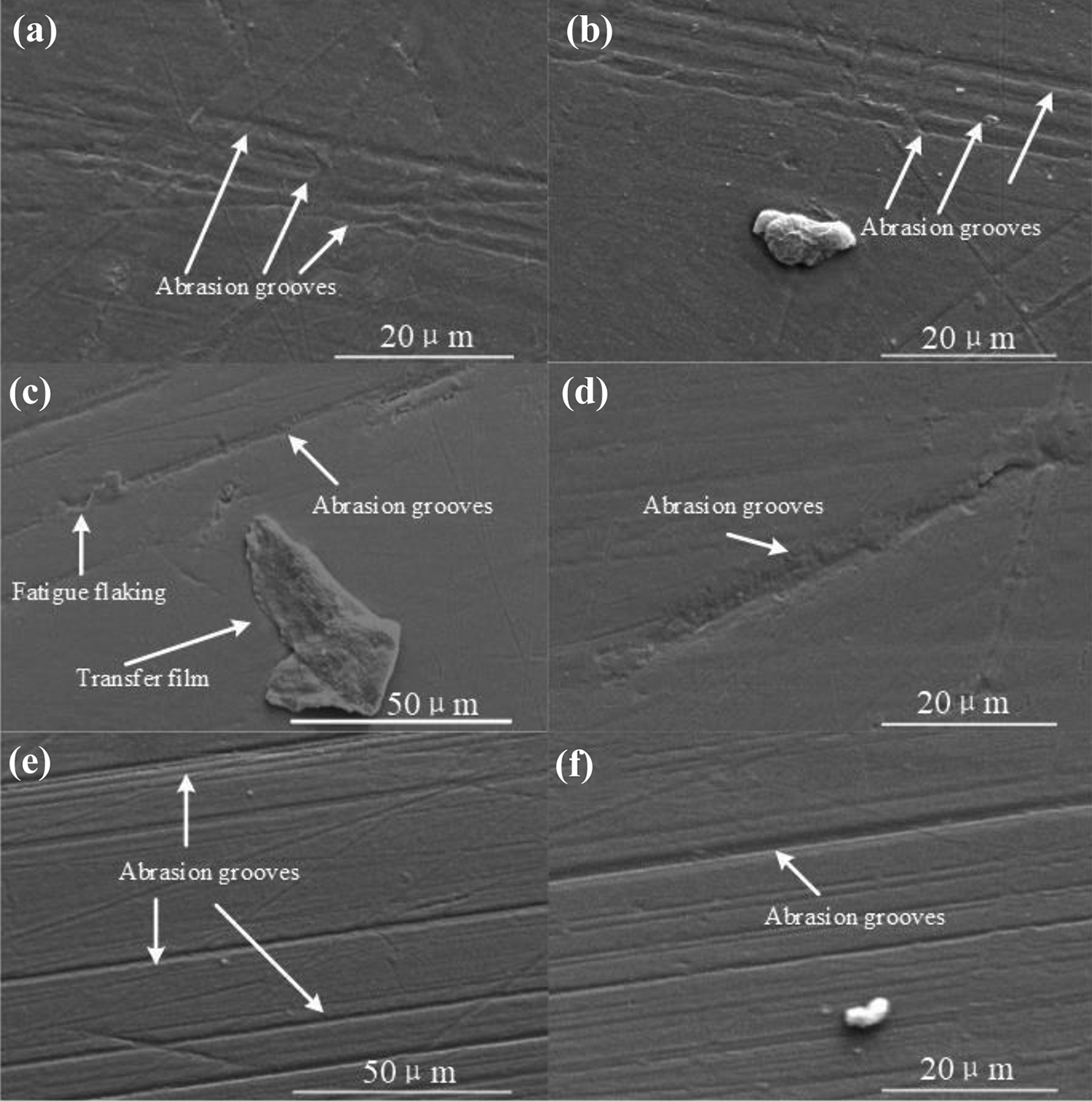
Scanning electron microscopic (SEM) images of worn surfaces of PEEK under different load conditions (a, b) 50 N, (c, d) 100 N, and (e, f) 150 N.
The worn surfaces of XLPE were shown in Figure 8 at loads of 50 N, 100 N, and 150 N. Under all loading conditions, the wear of XLPE was stronger than that of PEEK. Under the condition of 50 N load, the worn surface of XLPE was mainly composed of furrows with small depth and showed few traces of abrasive wear (Figure 8a, b). There were more furrows on the surface of XLPE, and the furrows were wider and deeper under a load of 100 N (Figure 8c). In addition, a few tears were found on the worn surface (Figure 8d). As shown in Figure 8e, f, the width and depth of furrows increased, and severe plastic deformation, adhesion, and flake spalling were found on the worn surface when the load reached 150 N.
SEM images of worn surfaces of XLPE under different load conditions (a, b) 50 N, (c, d) 100 N, and (e, f) 150 N.
Morphology of wear particles
The shape and texture of the particles generated from friction were associated with the wear mechanism of PEEK. 24 Figure 9 showed the morphology of wear particles under different loads. The morphology of PEEK wear particles obtained from the test was diverse and completely different from particles of XLPE and UHMWPE.25–27 Most wear particles were circular and oval particles, less than 10 μm. There were mainly small circular and oval particles with smooth edges and surfaces at loads of 50 N and 100 N (Figure 9a, b). With increased load, it became obvious that the amount and size of PEEK particles increased and their morphology became diverse(Figure 9c, d, e). Under a load of 150 N, in addition to the two kinds of particles above, large bar and lump particles were present, although these only formed a small proportion of particles. Bar particles with a smooth edge, no layer lines, and certain thickness were no more than 30 µm (Figure 9e). More particles were produced during the friction test. This suggests that its main wear mechanism was abrasive. 28 The surfaces of the friction pair interact with these particles, thus rubbing down their edges, which contributed to the production of a large amount of circular and oval particles. When the load increased, some large bar particles were broken into smaller particles because of surface extrusion.
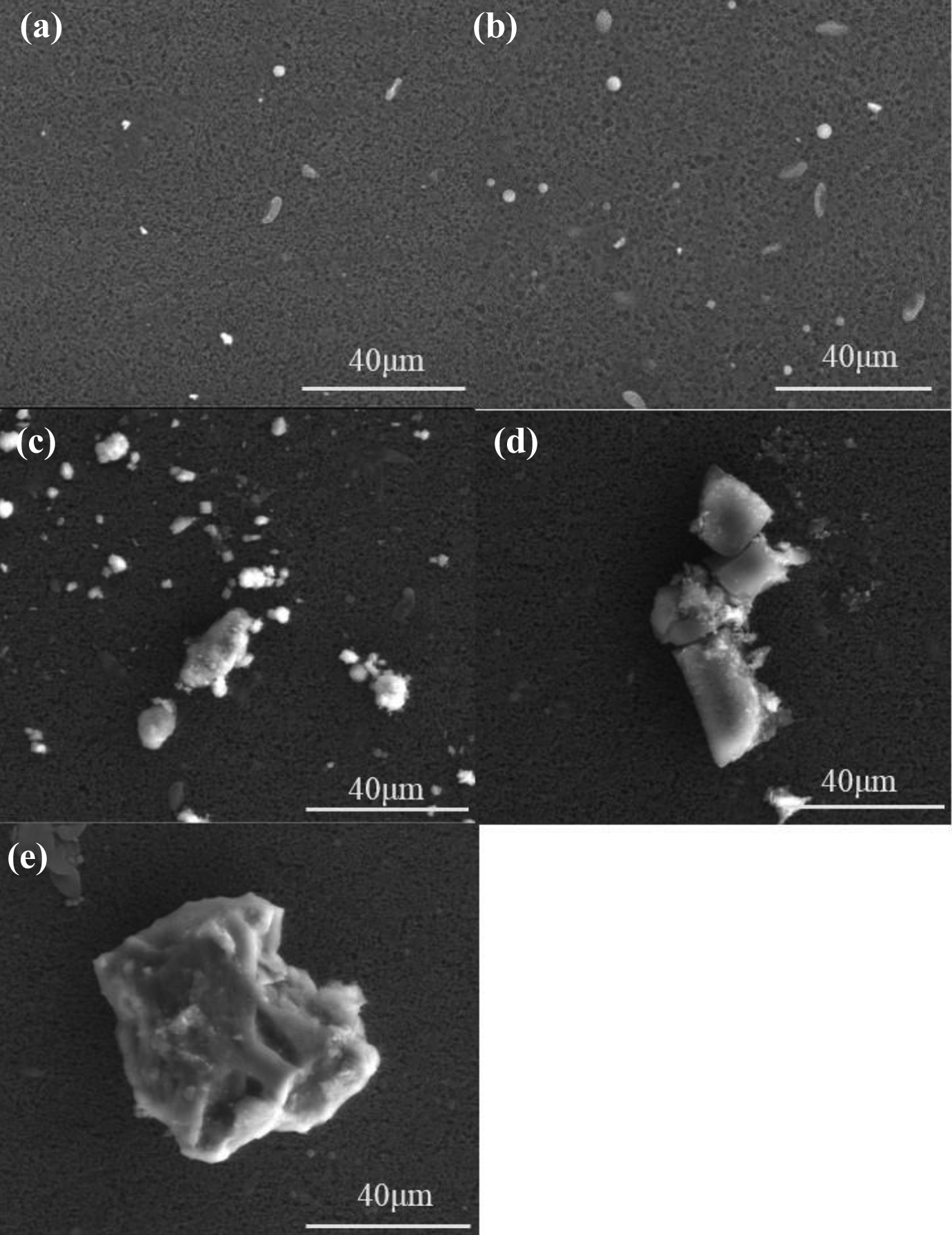
SEM images of wear particles of PEEK after wear test under different load conditions (a) 50 N, (b) 100 N, and (c, d, e) 150 N.
Discussion
During the process of friction, essentially, the molecules on the contact areas interact. The cross-linking point between molecules of thermosetting polymer decreases the interpenetration between chain segments. In the process of friction between thermoplastic and thermosetting polymers, interaction between molecules is not the main factor that affects the wear properties. 29 At the beginning of the friction, when the thermoplastic polymer with higher hardness and the thermosetting polymer was subjected to friction, the asperity on the worn surface of the two polymers was hard, which causing severe scratching. The friction coefficient was high because of scratching by the asperity of PEEK. As the friction progresses, the lubricating film of the saline is attached to the surface of the material, thus avoiding direct contact of the worn surface with the other surface, which can rapidly decrease the friction coefficient to its minimum. Because the stress was concentrated on the worn surface and particles, the particles severely scratched the surface of XLPE and PEEK, and the friction coefficient increased gradually. The friction coefficient reached steady state until the particles between the two interfaces became stable. The heat of friction increased with increasing load, which was followed by the reduction of the hardness of wear debris to improve lubrication. The friction coefficient decreased with increasing normal load. The wear mechanism was mainly slight abrasive at the lower load, with low wear loss. When the normal load increased, the surfaces of PEEK were plowed more seriously under the tangential force since the particles bear more force. The increased abrasive and fatigue wear lead to increased wear loss.
In the process of debris isolation, it is generally believed that ultracentrifugation leads to changes in the morphology of debris, and low-speed centrifugation does not interfere with the morphology of debris. However, short-time centrifugation may result in an insufficient settling distance. The method of isolating PEEK and XLPE from normal saline at the same time is needed to ensure that the two are completely separated. The settling velocity of PEEK particles with different sizes was calculated in NS. According to the results of the calculation, sufficient centrifugal time is determined to make peek and XLPE particles sink and float respectively. The FTIR spectrum showed that the separation of PEEK and XLPE can be realized under the condition of low-speed centrifugation. The FTIR absorption spectrum combined with SEM analysis confirmed that there were no organic and inorganic outside particles in the isolated particles. The isolating method used in the experiment is reliable.
The wear properties of thermoplastic polymer and thermosetting polymer were mainly related to differences in their hardness. The ball hardness of PEEK was 23.64 higher than that of XLPE. At the beginning of friction, the asperity of the PEEK surface pressing into XLPE caused large plastic deformation on the XLPE surface. Furrows on this surface were scratched by the asperity of the XLPE surface. Walls were produced by the accumulation of materials at the edge of furrows. The surface of PEEK was scratched by the hardening walls. Under the effect of shear force, these hardening points fell off into micrometer or submicron particles, and the elastic modulus of these particles increases. The main reasons for the large number of small particles were plowing and micro-cutting by asperity of specimen and particles. At the steady state, the stress hardening particles of XLPE and PEEK particles resulted in abrasive wear of PEEK. Higher stress harden walls were produced, which significantly increased the plowing effect on the surface of PEEK. More and larger PEEK particles and stress hardening XLPE particles were produced, which led to a more serious plowing on the friction pair. It is generally assumed that fatigue wear is the main reason for the emergence of large particles. When the load increased, the sliding surface temperature increased rapidly, plastic deformation increased and strength decreased, and the wear mechanism changed into abrasive wear and fatigue wear.30–32 When the load increased, the deformation led to stress concentration of surface and subsurface. The evolution of space deformation and the structure of the surface and subsurface gradually accumulated until plastic deformation was limited during repeated movement. It was difficult to be destroyed when the direction of the load was in accordance with the direction of the anisotropic material crystal structure because the material had a large impedance in the main direction of the lamellar structure. When the direction of the load was perpendicular to the direction of the isotropic material crystal structure, it could be damaged easily because of the weak impedance of the material in the normal direction of the lamellar structure. The molecular chains in the amorphous region were stretched, distorted, and broken under alternating stress, thus resulting in a directional distribution of random crystal along the sliding direction. When the shear stress exceeded the critical stress of the dislocation movement, crystal plane slipping was produced. 33 The crystal layers were preferentially oriented along the sliding direction, and the distance between layers increased. As the friction continues, the chains between crystals broke. The resulting cracks spread from the inside to the outside of PEEK, and then, block particles were stripped from the surface. These cracks continued to expand, resulting in fatigue wear of PEEK. Large wear particles were stripped or peeled from PEEK. Wide grooves on the surface formed because of large wear particles, which contributed to great wear loss.
In summary, a low-speed centrifugation method for simultaneous separating PEEK and XLPE proposed realized the separation of two polymer particles completely. It was of great significance to the analysis of wear particles and wear mechanism. Secondly, combined with the results of friction under different normal loads, the wear mechanism was deeply explored according to the debris analysis. When the load was small, it was mainly abrasive wear, and the small particles produced by wear played a role in lubrication. At high load, the increase of friction heat softened particle surface which increased lubrication. However, plastic deformation of XLPE increased at a high load. In addition to abrasive wear, fatigue wear occurred. Some of the large particles produced by fatigue wear were pressed into the worn surface of the friction pair and led to deeper furrows, resulting in wear increasing.
Conclusions
The present study conducted a pin-on-plate test, with PEEK sliding against XLPE in 0.9% NS. The main outcomes of this work were as follows:
PEEK had a low friction coefficient and good anti-wear properties. The friction coefficient decreases with increasing of load, ranging from 0.06 to 0.115. The wear loss of PEEK increased accordingly with the load.
The method of isolating PEEK particles was effective to obtain micro and nanoparticles. Granular analysis indicated that the particle distribution was relatively concentrated, with 96% of wear particles being smaller than 10 μm. With increasing of load, the percentage of particles larger than 10 µm increased.
The main wear mechanism is abrasive wear when the load was 50 N. The morphology of wear particles was small spherical and oval. When the load increased to 100 N, large block particles were generated because of tearing. With increasing load, the main wear mechanism was adhesion wear and fatigue flaking. Several block, bar, and slice particles were produced during friction under high stress, which indicated abnormal wear. Several large particles caused severe damages to the surface of friction pairs and accelerated wear of the friction pairs.
Footnotes
Funding
The author(s) disclosed receipt of the following financial support for the research, authorship, and/or publication of this article: This class file was developed by the Fundamental Research Funds for the Central Universities (No. 2017XKZD08) and Priority Academic Program Development of Jiangsu Higher Education Institutions (PAPD).