
Abstract
In the present paper, the influence of tailored load introduction inserts applied to a bolt-loaded open-hole injection plate with different short glass fibre content is investigated. The tailored load introduction inserts made with a Tailored Fibre Placement (TFP) process, as well as open-hole injection plates without an insert were considered as reference samples. The samples were tested under tensile bolt-loading. The influence of the TFP-inserts on the load bearing properties of the open-hole injection plates was investigated. The test results show a huge increase of the load-carrying ability of the short-glass-fibre specimens when TFP-inserts are integrated. Moreover, the damage tolerance was dramatically improved as the specimens with integrated TFP-inserts did not fail abruptly and a residual strength higher than the strength of the test specimen without insert could be observed. However, the strength of the test specimen with integrated insert did not exceed the strength of the insert itself in most cases.
Keywords
Introduction
One of the main challenges of lightweight design with fibre reinforced composites is to manufacture components with the required mechanical performance in series production with short cycle times at low cost
As complex structures are made up of single parts, they need to be joined. One of the main challenges of differential constructions is the right choice of the joining method.
5
Generally, there are two common joining methods for composite structures: mechanically fastened joints
6
and adhesively bonded or welded joints
A number of studies investigated how to increase the bearing strength as well as the notch strength in composites.9–11 To improve the mechanical properties, metallic inserts are commonly used.12,13 This however, leads to an increased mass of the component, which can be inconsistent with weight-reduction methods. Another approach is to reinforce the structure locally by embedding continuous fibres along critical load paths. Here different technologies can be used. Investigations of the Tailored Fibre Placement (TFP) technology show that open-hole laminates with local fibre reinforcement reach the same strengths as measured on the unnotched plates.14–16 Possible geometries of the stitched reinforcements can be spiral, starshaped or consist of a large number of individual loops made of unidirectional strings (UD-strings) evenly distributed within the loaded area. 17 Additionally, winded carbon fibre rovings can be used to reinforce bolt-loaded open-holes. 18
The utilization of short-fibre-reinforced thermoplastics in engineering applications has increased strongly in the last years. 19 Recent studies on short-fibre-reinforced thermoplastics investigated how to increase the mechanical performance of such components locally by integrating continuous fibre-reinforced sheets.20,21 Concerning material efficiency, the use of continuous fibre-reinforced sheets is disadvantageous, since they need to be cut to the contour before processing and have a high degree of waste. Furthermore, there is a poor utilisation of the fibre performance of the sheets since the cost-intensive reinforcing fibres are applied to areas of lower stresses as well. Previous studies have shown that the integration of local reinforcements based on continuous fibre in injection moulding is possible3,10,11 and is more weight efficient than the use of fibre-reinforced sheets, as the continuous fibres are placed along the critical load path.
Unlike the previous investigations where open-hole laminates were reinforced through tapes 4 or winded patches, 18 the present work deals with the reinforcement of open-hole injected thermoplastic plates. Due to the non-directional fibres and the high matrix proportion, the bearing strength of short-fibre thermoplastics is low, which makes local thickenings necessary. Highly stress-resistant components still cannot be produced with current methods. In this work, the influence of tailored inserts on the failure behaviour of injected thermoplastic plates under tensile load is investigated. The behaviour of three different insert geometries was compared and the influence of the short-fibre content on the overall mechanical performance was analysed. The load at damage initiation und the residual strength were considered for the evaluation of the mechanical performance.
Material, manufacturing and testing
Design of specimens
The specification of the geometrical parameters of a load introduction insert was conducted with the help of the analytical calculation model for laterally supported loop connections by Conen, see Eq. 1 and Figure 1.22,23 In laterally supported loop connections the fibre failure is the critical one. Hence, the tangential stress is determined. Assuming the maximum fibre elongation as failure type, maximum transmittable force can be determined depending on the internal diameter and the width of the loop. 17

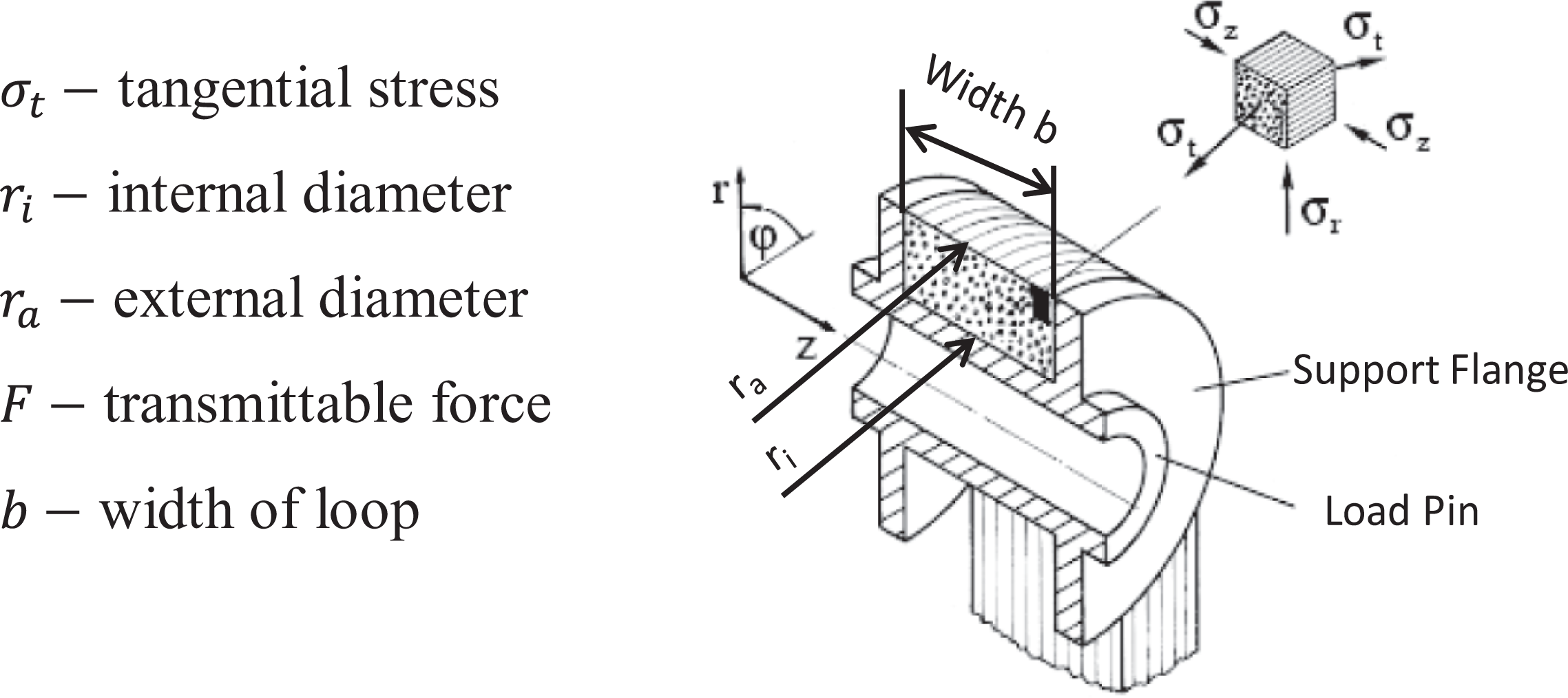
Lateral supported loop connection. 17
An increasing internal diameter leads to an asymptotic approximation to the maximum transmittable force, see Figure 2. The bigger the loop’s width is chosen, the higher is the transmittable force for same internal diameter.
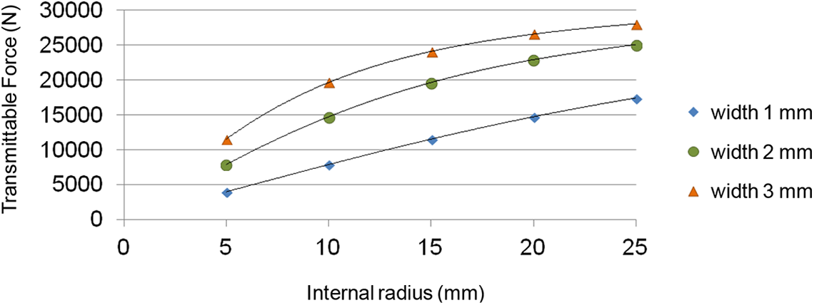
Function of the internal radius and the width of a lateral supported loop as well as the resulting of maximum transmittable force – applies to all parameters the same cross-sectional area of 10 mm2 in the apex of the loop.
In the current investigation, three types of load introduction inserts were designed, as shown in Figure 3. All inserts have an internal diameter of 20 mm where the load introduction occurs. To study the failure behaviour of different insert configurations, different ratios of outside radius to inside radius were investigated. Insert type A has a ratio of the outside radius (Ro = 20 mm) to the inside radius (Ri = 10 mm) of Ro/Ri = 2.0. Insert type B has a ratio of the outside radius (Ro = 17 mm) to the inside radius (Ri = 10 mm) of Ro/Ri = 1.7. There are two small boreholes with a diameter of Ø 3,2 mm at the bottom of both types A and B to fix the insert against rotation in the injection moulding tool during the injection process. The insert type C has a ratio of the outside radius (Ro = 14 mm) to the inside radius (Ri = 10 mm) of Ro/Ri = 1.4. Furthermore, the load is introduced at insert C from both sides. To provide laterally supported loop connections, a shoulder bushing with a shoulder diameter of 28 mm was integrated in all three types of inserts. While the insert type C is completely supported by the bushing at the load introduction, the bushing flange covers only a portion of inserts type A and B, as the outer diameter of the insert is larger than the flange diameter of the bushing.
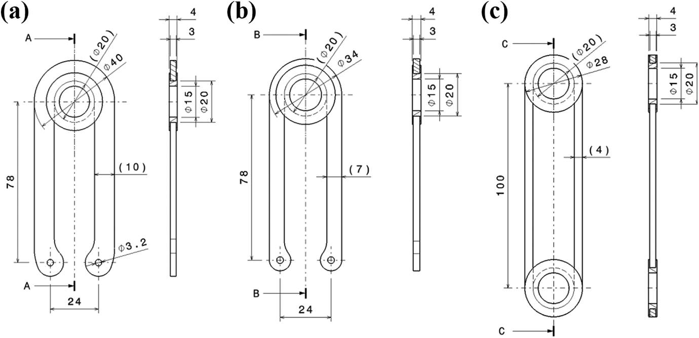
Geometry design of the load introduction inserts a) type A, b) type B and c) type C.
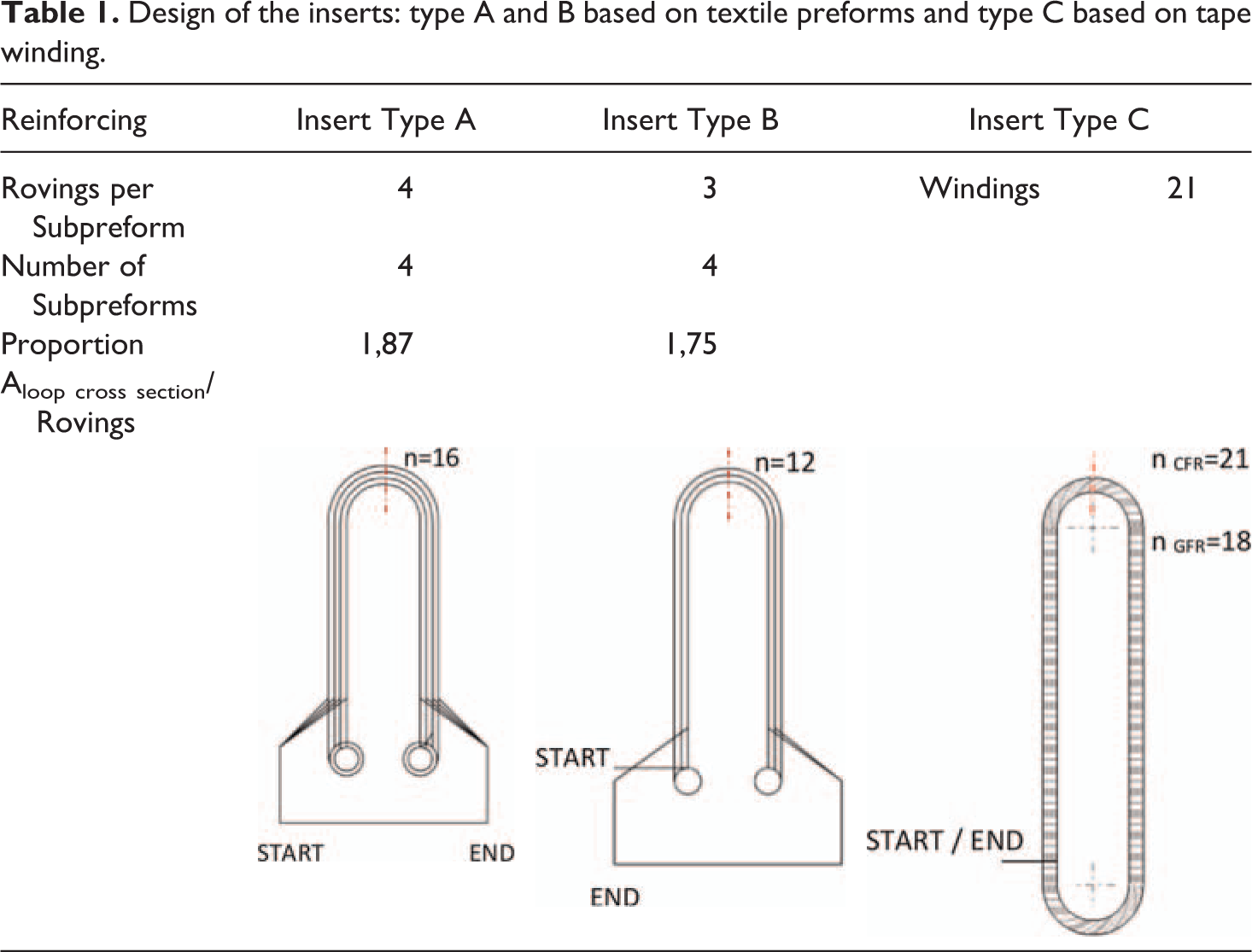
Table 1 shows the design of the three types of load introduction inserts. While insert type A contains four rovings per sub-preform in the loop area, insert type B contains three rovings. The reason for this difference is explained by the different cross sectional area of the inserts caused by different ratio of the outside radius to the inside radius. Both inserts contain four sub-preforms and therefore nearly the same proportion of the area of loop cross section to the total amount of rovings. The insert type C has 21 windings of carbon fibre rovings which have been wrapped around the bushings.
Design of the inserts: type A and B based on textile preforms and type C based on tape winding.
To investigate the influence of the load introduction inserts on short fibre reinforced thermoplastics, open hole plates with a thickness of 4 mm, a length of 180 mm and a width of 50 mm were designed as shown in Figure 4. A bore hole with a diameter of d = 15 mm and an edge distance of 2,6 * d was considered to initialize bearing stress failure. 9
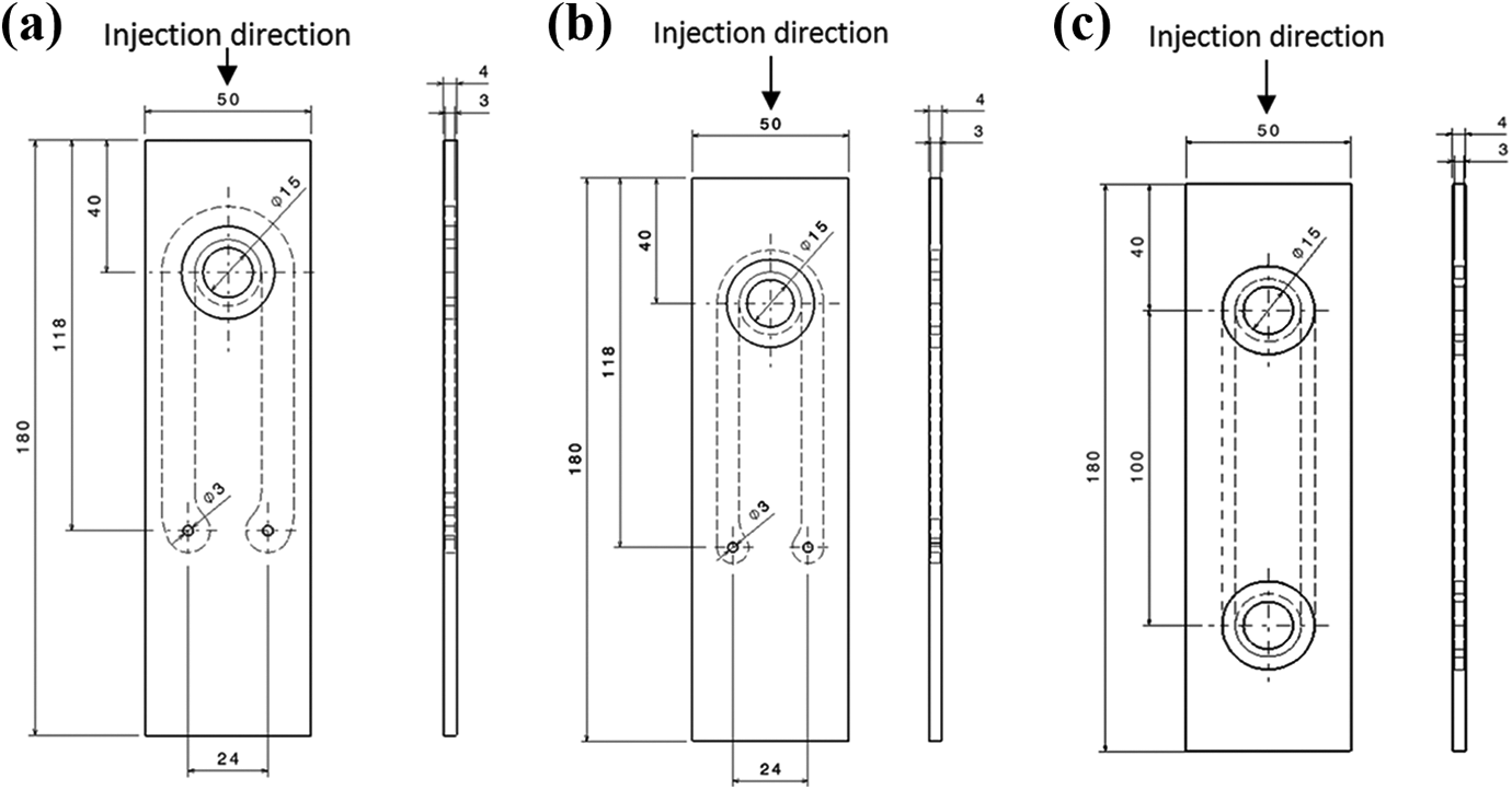
Dimensions and injection direction of the injected open-hole specimen a) with insert type A, b) with insert type B and c) with insert type C.
Materials and manufacturing
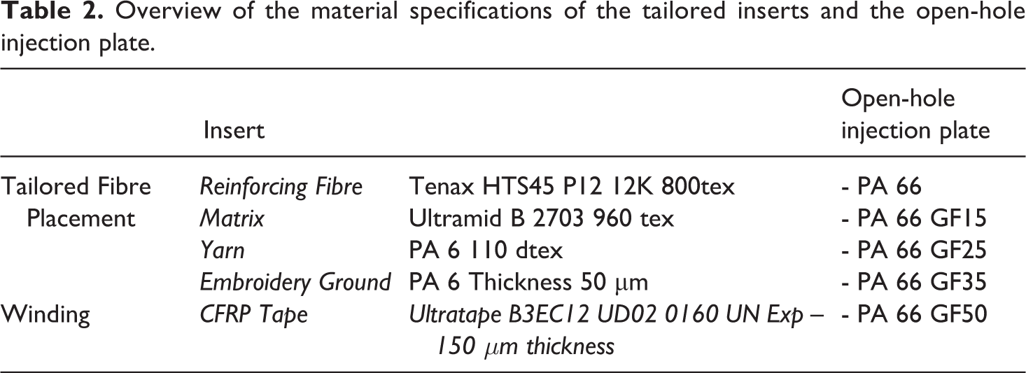
Table 2 gives an overview of the material specifications of the inserts as well as the open-hole injection plates. To manufacture the different types of inserts two manufacturing processes and thereby two types of materials were used. The process flow of the manufacturing of the test plates with integrated inserts is shown in Figure 5.
Overview of the material specifications of the tailored inserts and the open-hole injection plate.
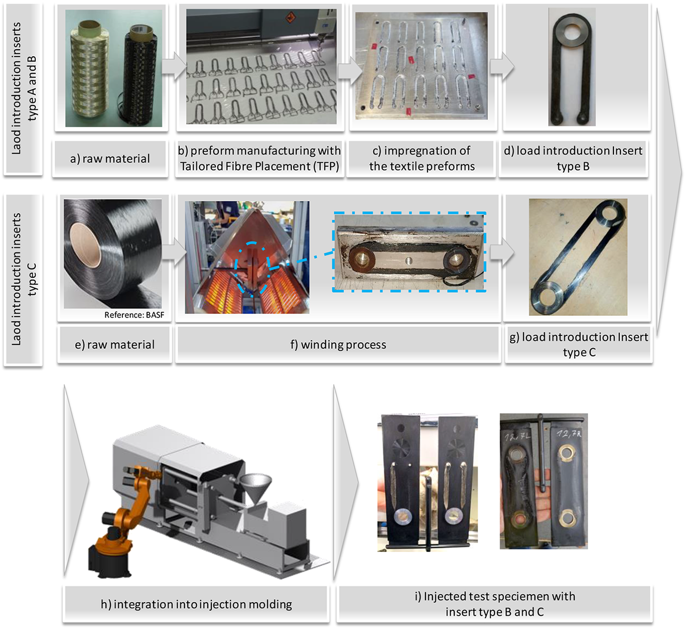
Process flow of the fabrication of the inserts and the integration into injection moulding.
For inserts type A and B the Tailored Fibre Placement (TFP) technology was applied where a hybrid yarn consisting of a thermoplastic fibre and a reinforcing carbon fibre was used, see Figure 5 a). The thermoplastic fibre which represents the matrix in the consolidated composite, were yarned out of Ultramid B27 03 (PA 6) at Faserinstitut Bremen. A Tenax HTS45P12 12 k roving was used as reinforcing carbon fibres.
The hybrid yarn was aligned to the main load paths in the plate, which have been previously determined, with the TFP machine (JGW 0200-550 ZSK GmbH) and the Side-by-Side process, see Figure 5 b). 23 For the embroidery ground a PA 6 foil of 50 µm was used. To fix the hybrid roving on the embroidery ground a PA 6 yarn with 110 dtex was employed. The subsequent consolidation of the hybrid preform was performed with a variotherm moulding process, see Figure 5 c). During the consolidation, the thermoplastic yarns melt and form the matrix while coating the carbon fibres.
To manufacture insert type C, a thermoplastic tape winding process was applied. For this purpose an Ultratape B3EC12 UD02 0160 UN Exp, provided by BASF, was used, see Figure 5 e). This tape contained a 12 k carbon fibre roving and a PA 6 matrix. The tape was cut to a width of 3 mm. The winding process was performed at 270°C and the heat introduction occurred by convection using an electric heater, see Figure 5 f). The tape was wound directly around two shoulder bushings, which were placed with a distance of 100 mm from each other. During the winding process an initial load of 35 N was applied to the tape to ensure a tightening of the tape. The consolidated inserts type A, B and C can be then stored or integrated directly in a forming process such as injection or compression moulding, see Figure 5 d), g), h) and i).
To analyse the influence of the stiffness of the injected thermoplastic material on the failure behaviour of the injected test specimens, the thermoplastic material PA 66 with 0 vol.%, 15 vol.%, 25 vol.%, 35 vol.% and 50 vol.% short glass fibber (GF) content was used. PA 6, which represents the matrix of the insert, and PA 66 that represents the matrix of the injection moulding, are compatible materials, so that adhesive bonding 6 of the insert and the injected thermoplastic material is possible. Eight samples per configuration were fabricated in cooperation with Weberit Werke Dräbing GmbH by injection moulding, with the different load introduction inserts integrated in the mould. The inserts have not been preheated. The injection into the mould occurred from the short side above the bore hole of the specimen, see Figure 4.
Test setup and test procedure
The tensile tests were performed on a universal tensile testing machine Zwick Roell Z250 rig with 250 kN force at 23°C, 50% air humidity,0,5 N preload and 2 mm/min test speed. The test procedure was performed based on DIN 65562 9 using a bolt with a diameter of 15 mm. The test setup of the tailored load introduction inserts with different configurations is shown in Figure 6. To test the single load introduction of the inserts type A and B as well as the injected open hole plates with integrated insert, one bolt was applied at the loop region for load introduction, see Figure 6 a) and b). The bottom area was fixed between two clamping jaws. To test the single insert type C and the injected open hole plates with integrated insert C, the load was applied through two pins at the upper and the lower turn of the insert, see Figure 6 c). Five samples per configuration were tested. The damage evolution was visually monitored and the load-displacement curves of the test specimens were recorded.
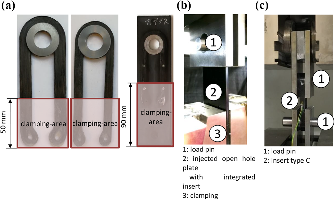
Test setup for tailored load introduction inserts a) load introduction insert type A and B and injected open hole plate with integrated insert, b) test setup for single inserts type A and B and injected open hole plates with integrated insert, c) test setup for single insert type C and injected open hole plates with integrated insert type C.
Test results
Single inserts
Insert type A and B
The load-displacement curves of the single inserts type A and B are shown in Figure 7. The average load of inserts Type A reaches about 18.04 kN. The value of the average displacement at total failure is about 6.62 mm. The average displacement at failure initiation, which can be seen at the first force peak is about 2.18 mm. The average load of insert type B is a bit lower than of type A and reaches about 16.53 kN. The value of the average displacement at total failure is about 2.97 mm. The average displacement at failure initiation is about 1.88 mm. It is evident that both insert types do not fail abruptly, rather they offer a good-natured damage tolerance behaviour, as it continues to carry load after damage initiation. This behaviour is caused by the TFP process as there is no pre-tension of the fibre in the stitching process. In this way the fibre rovings lie individually in the composite and fail sequentially, what can be seen in the progressive decrease of the force after first damage.
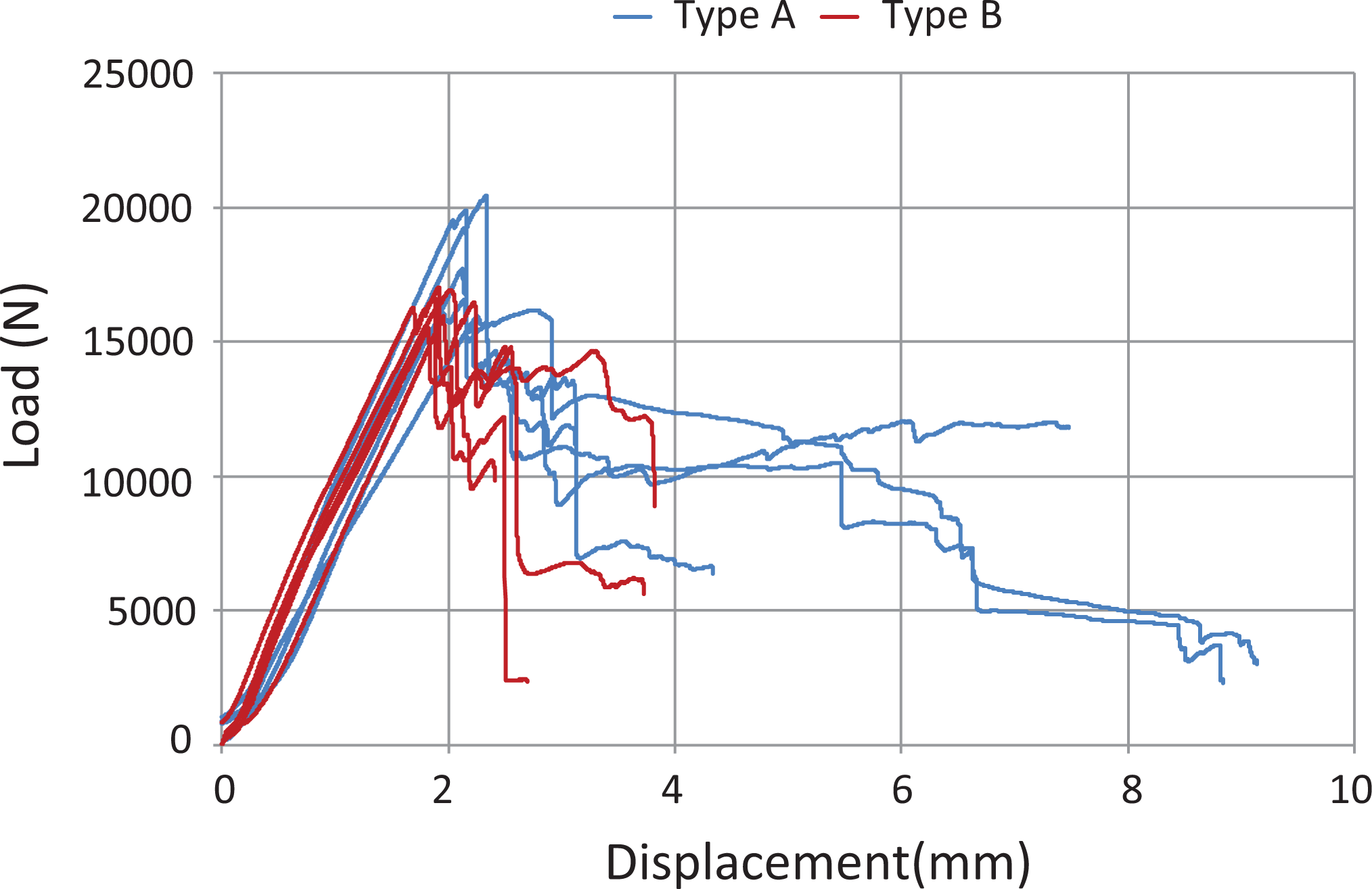
Load-displacement curves of insert type A and B under tensile load.
Figure 8 shows the damage that occurred in inserts type A and B during the tensile tests. All inserts failed at the transition between the loop and the straight shaft. The fracture behaviour corresponds to the fracture behaviour found in the literature. 10 The reason for this behaviour is the local excessive tension in the transition between the loop and the straight shaft caused by superimposed bending stresses in this area.
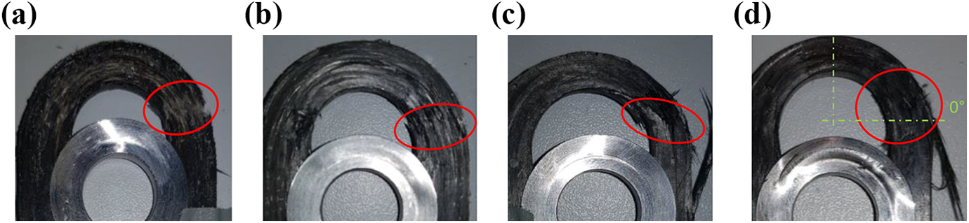
Exemplary illustration of fractured inserts type A (a and b), and type B (c and d).
Insert type C
The results of the tensile tests of inserts type C are shown in Figure 9. The average load reached about 22.982 kN. The average displacement at total failure is about 2.32 mm. Compared to the average displacement at total failure of the inserts type A and B, the elongation of the winded inserts type C is a bit lower. Furthermore, they do not show a decent damage behaviour as they fail abruptly. The reason for this behaviour could be the preload force induced during the winding process that compact the individual tape layers in the loop area. In this case the rovings fail together at the same time. Therefore, higher average loads can be reached as well as an abrupt damage behaviour without residual strength can be observed.
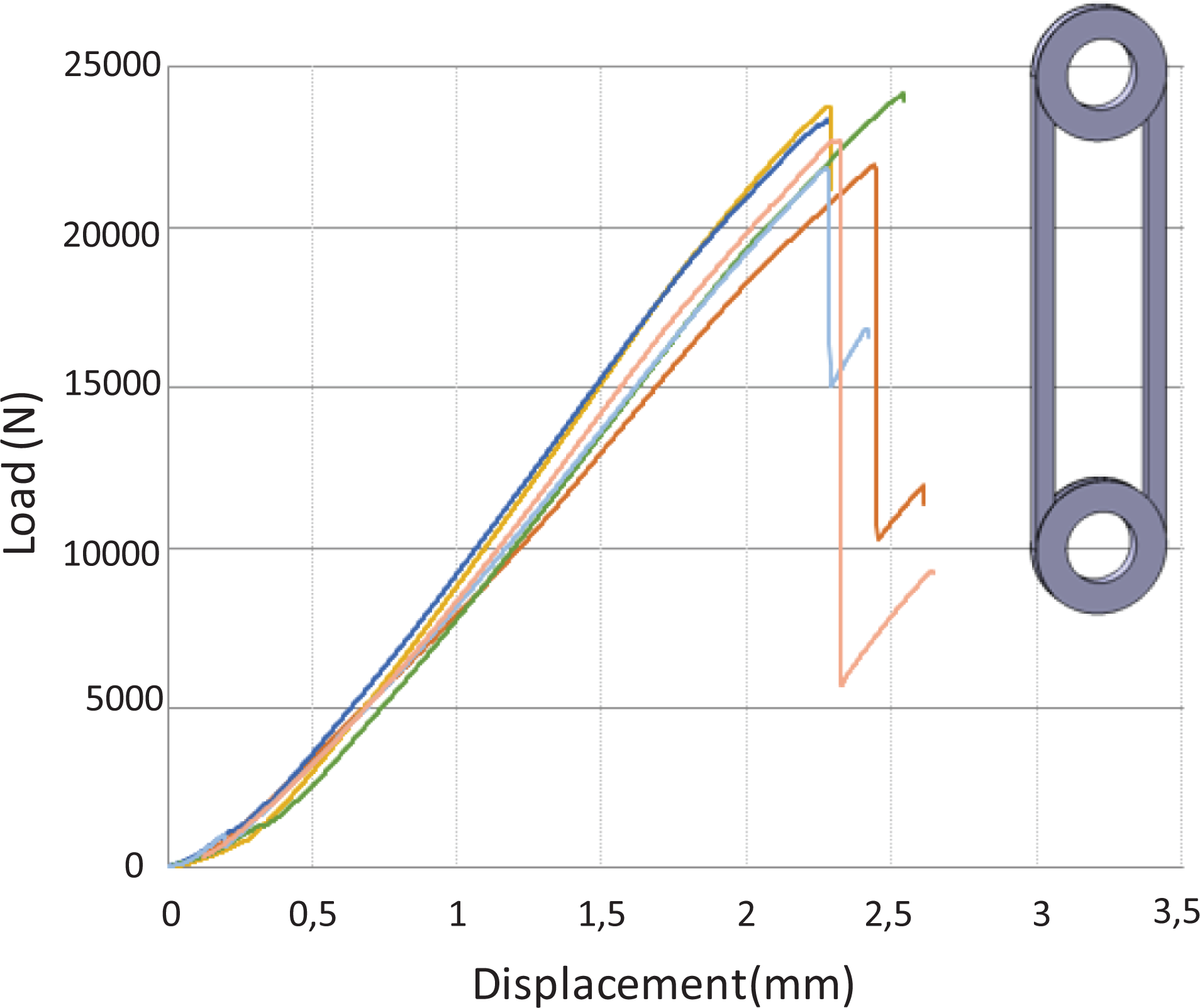
Load-displacement curves of inserts type C.
An example of fractures in inserts type C is shown in Figure 10. The winding inserts showed the same fracture location as inserts type A and B and correlated with the fracture behaviour found in the literature. 10
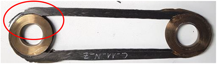
Example of damage in insert type C.
Open hole injected plates with integrated inserts under bearing load
Specimens with insert type A
To investigate the influence of the insert on the short fibre reinforced thermoplastic plates, specimens without inserts were tested as reference. Moreover, the short-glass-fibre volume content in the thermoplastic plates was varied (0%, 15%, 25%, 35% and 50%).
Figure 11 shows the load displacement curves of the plates with PA 66 with 15 vol.% (V15), 25 vol.% (V25), 35 vol.% (V35) and 50 vol.% (V50) short-glass-fibre content. Due to a malfunction in the test setup, samples with 0 vol.% (V0) and insert type A could not be evaluated. As expected, the load and stiffness of the reference samples increases and the displacement decreases as the proportion of short glass fibre content increases. All samples failed abruptly without residual strength.
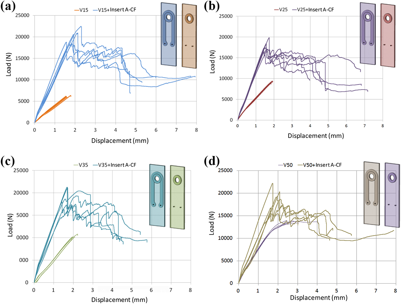
Results of tested open hole injected plates type A with different short-glass-fibre volume contents: a) 15 vol. % (V15), b) 25 vol. % (V25), c) 35 vol. % (V35), d) 50 vol. % (V50).
By integrating a reinforcing insert type A, the failure behaviour of the injected open hole plates change significantly. The positive influence of the insert is evident as it lead to the increase of the maximum load of the injected open hole plates as well as the stiffness.
Specimens with 15 vol.% (V15) and insert type A reached in average a reaction force of about 20 kN instead of 6.2 kN without insert. In this case the integration of the insert lead to an advantage of plus 210%.
Furthermore, integrating an insert of type A into the specimen changes the damage propagation. While the specimens without insert failed abruptly, the plates with insert exhibited a residual strength and showed a better damage tolerant behaviour. The first force drop can be seen for all specimens at about 2 mm displacement. Here the force decreased in average by about 20%. Then the load remained at this level and the specimens fail totally at about 5.5 mm displacement. Generally, the curves of the specimens with integrated insert type A correspond very well with the curves of the single inserts in Figure 7.
Figure 12 summarizes the load and the displacement at damage initiation of all tested specimens depending on the short-glass-fibre volume content of the injected plate without V0. The injected plates with integrated inserts show loads between 18 and 20 kN, which is nearly the same performance as that of the single insert type A with approximately 18.05 kN. The influence of the short-glass-fibre content on the mechanical performance of the specimens is not obvious for this insert geometry.
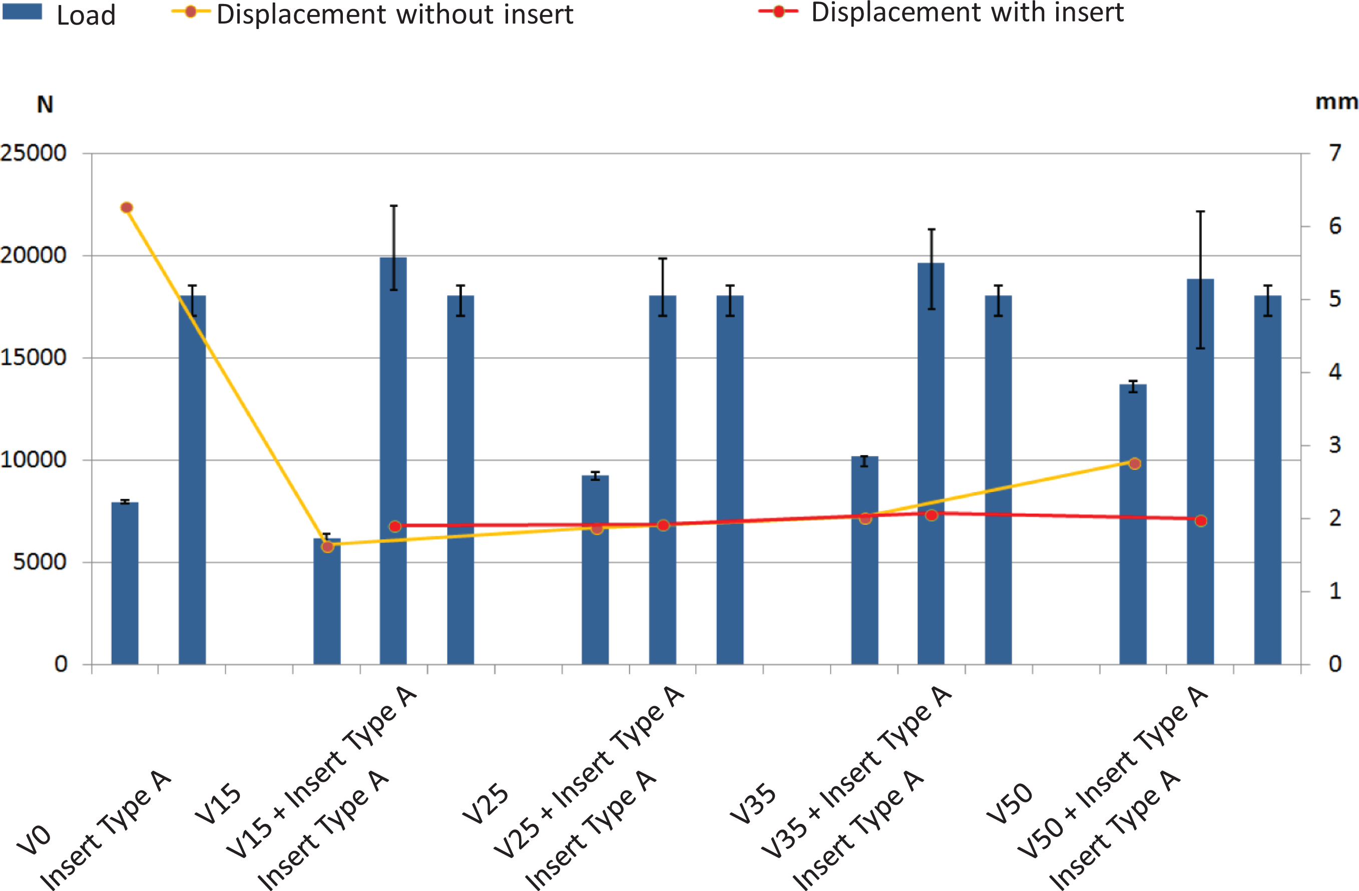
Influence of the insert type A on the injected open-hole plates with different short-glass-fibre content.
Figure 13 shows examples of damages in the open hole injection plates with integrated insert type A made of carbon fibre reinforced plastic (CFRP). All specimens failed in the bolt area. It is clear, that the flanges of the metallic bushing are bent apart due to the lateral sliding of the single layers as result of the radial stresses at the inside radius of the loop. The bushing flange covers only a portion of the insert and the outer diameter of the insert is larger than the flange diameter of the bushing, which creates high bending loads in the bushing flanges.
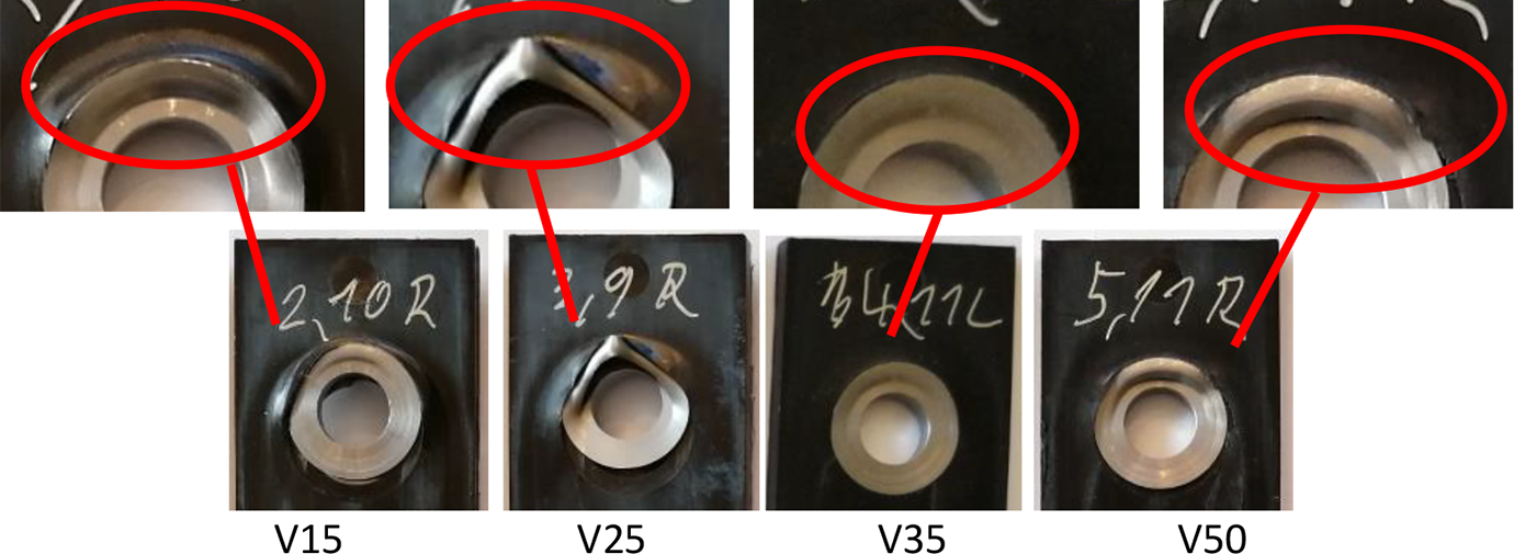
Damage behaviour of tested open hole injected plates with different short glass fibre content and integrated type A insert.
Specimens with insert type B
Figure 14 shows the load displacement curves of the reference samples as well as samples with insert type B. Except of reference specimens with 0 vol.% (V0) short glass fibre content, all samples failed abruptly without residual strength, see Figure 14 a), while the specimens without short-glass-fibres showed a high plastic deformation.
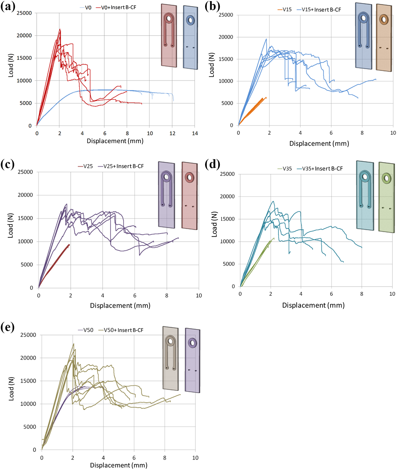
Results of tested open hole injected plates type B with different short-glass-fibre volume contents: a) 0 vol.% (V0) b) 15 vol.% (V15), c) 25 vol.% (V25), d) 35 vol.% (V35), e) 50 vol.% (V50).
As already observed in the test with insert type A, the failure behaviour of the injected open hole plates with insert type B has changed significantly compared to the reference plates without inserts. Here the positive influence of the insert is evident as it increases the maximum load of the injected open hole plates as well as the stiffness. Specimens with 15 vol.% (V15) and insert type B reached an average reaction force of about 17,2 kN instead of 6,20 kN without insert. In this example the integration of the insert led to an advantage of plus 177%.
The first drop in load can be seen for all specimens with insert type B at about 2 mm displacement. The force decreased as well in average by 20%. After that the load remained at this level and the specimens fails totally at about 6 mm displacement. Instead of failing abruptly, the insert offers a damage tolerant behaviour though the residual strength. In general, the curves of the specimens with integrated insert type B correspond very well with the curves of the single inserts in Figure 7.
Figure 15 summarizes the loads and the displacements at damage initiation of all tested specimens depending on the short glass-fibre-volume content of the injected plate. The injected plates with insert show a load level of approximately 17 kN, which is nearly the same load level of the single insert type B. The only outlier was observed with the average load of the 50 vol.% (V50) injected plates, which provides a slightly higher load carrying capacity of 20.3 kN. This sudden increase of the reaction force is possibly caused by the high scatter of the load displacement curves of the specimens with 50 vol.% short-fibre-volume content. The same observation is valid for the displacement at failure initiation as nearly all specimens failed at about 2 mm.
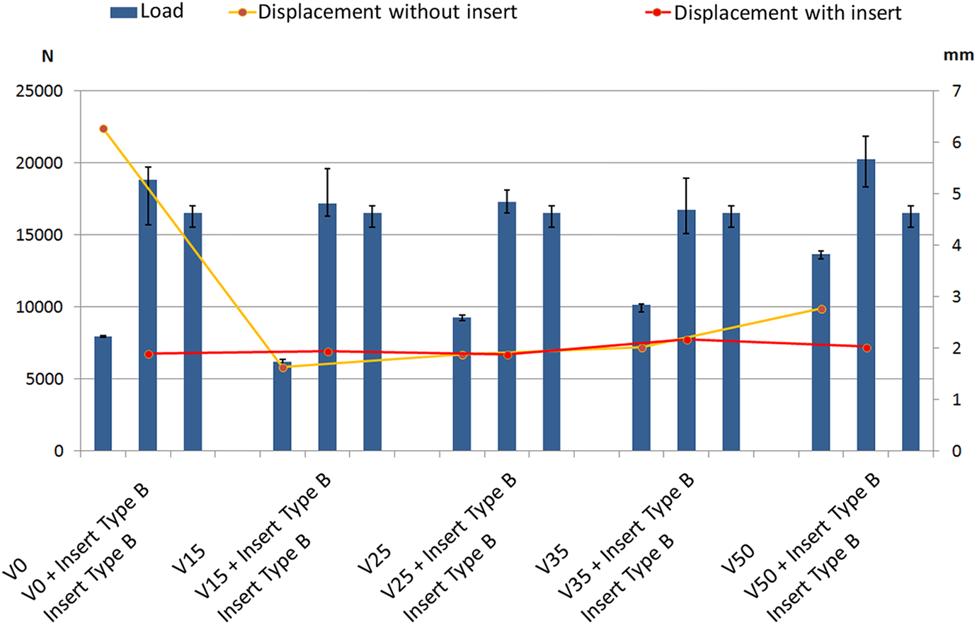
Influence of the insert type B on the injected open-hole plates with different short-glass-fibre content.
Figure 16 shows examples of damages in the open hole injection plates with integrated insert type B made of carbon fibre reinforced plastic (CFRP). All specimens failed in the bolt area. It is clear that the flanges of the metallic bushing are bent showing similar behaviour to the plates with integrated type A inserts.
Damage behaviour of tested open hole injected plates with different short-glass-fibre content and integrated insert type B.
Specimens with insert type C
Furthermore, open hole injection plates with integrated inserts type C were tested. The test results are shown in Figure 17. Specimens with a short-fibre-content of 0 vol.% without insert reached a maximum reaction force of about 10 kN with a displacement at break of about 25.6 mm. The high plastic deformation ensured that the load of specimens with 0 vol.% (V0) fibre content increased slowly and so reached a value higher than that of the specimens with 15 vol.% (V15) fibre content. By adding 15 vol.% short-glass-fibre the displacement decreases from 25.6 mm to 1.9 mm. Adding short-glass-fibres to the thermoplastic material led to the embrittlement of the material and the maximum reaction force surpassed the 10 kN for the plates with 35% and 50% short-fibre-volume content.
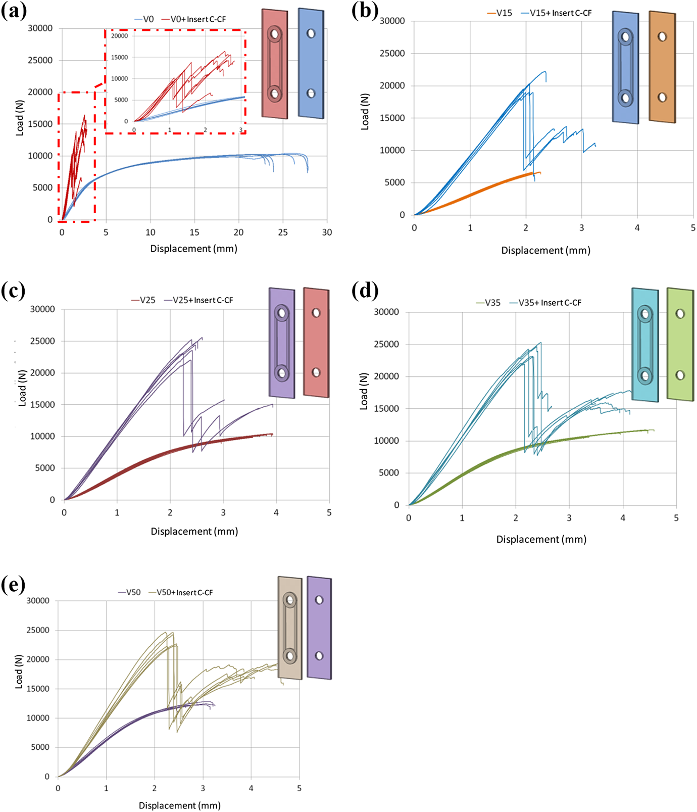
Results of tested open hole injected plates type C with different short-glass-fibre content: a) 0 vol.% (V0), b) 15 vol.% (V15), c) 25 vol.% (V25), d) 35 vol.% (V35), e) 50 vol.% (V50).
The specimens with a short-glass-fibre volume content of 0% and insert type C reached an average maximum reaction force of 12 kN. Specimen with 25 vol.% short-glass-fibre reached an average force of 23.6 kN. This increase of 96% of the load is observed also with a higher short-fibre volume content, but the loads remains at the same level like in specimens with 25% short-fibre volume content.
Moreover, specimens with insert type C show a different displacement (behaviour). Although the single inserts type C failed abruptly and did not exhibit residual strength (see Figure 9), the injected plates with integrated insert did. Except for specimens with 0 vol.% short-glass-fibre content, the first drop in force can be seen for all specimens at ca. 2.3 mm displacement. Here the force decreased in average by 45%. Then the load increased again by ca. 20% and total failure occured at a displacement between approx. 2.6 mm and 4.3 mm. It should be noted that the displacement at total failure increases upon increasing the short-glass-fibre content in the injected plates. While the specimens with 0 vol.% (V0) and insert type C failed at 2.6 mm displacement, the specimens with 50 vol.% (V50) failed at about 4.33 mm.
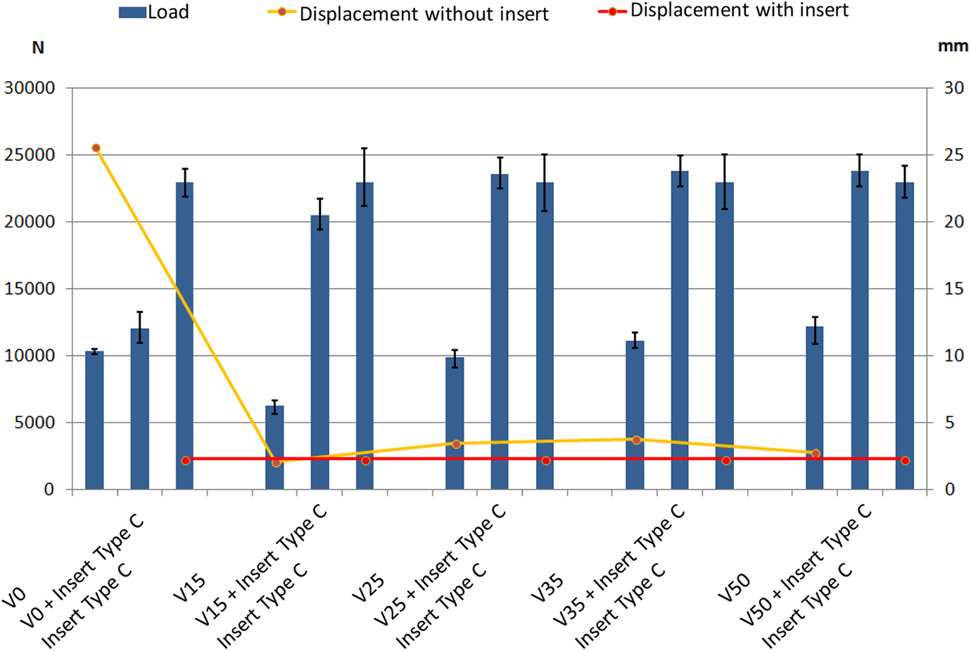
Figure 18 summarizes the load and the displacement at damage initiation of all tested specimens depending on the short-glass-fibre volume content of the injected plate. The specimens with 15 vol.% (V15) to 50 vol.% (V50) short-glass-fibre content with insert type C reached the load level of the single insert (approx. 23 kN). Only specimens with 0 vol.% (V0) did not reach the load level of the bare insert. Here the load could be increased by only ca. 39%.
Influence of the insert type C on the injected open-hole plates with different short-glass-fibre content.
One of the reasons for this behaviour is the lower strength of the V0 injected material. The average load of 10 kN observed in the plates without insert could only be achieved at an average displacement of 25.6 mm. However, such high elongation values are not practical. In this case if the average load at an elongation of 0.2% is considered, only a load of about 3.7 kN would be reached. If this load is used as a comparison, the load was increased by 287% through adding an insert type C to the injected plate. Observing the damage specimen depicted in Figure 19 confirms this hypothesis of low material strength, as the injected material in specimens with 0% and 15% short-fibre volume content started to fail at early stages of the test, which led to an abrupt damage behaviour and the complete loss of the residual strength.
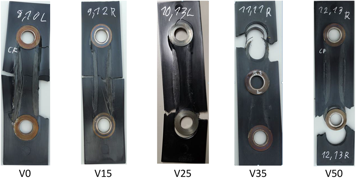
Damage behaviour of tested open hole injected plates with different short-glass-fibre content and integrated insert type C.
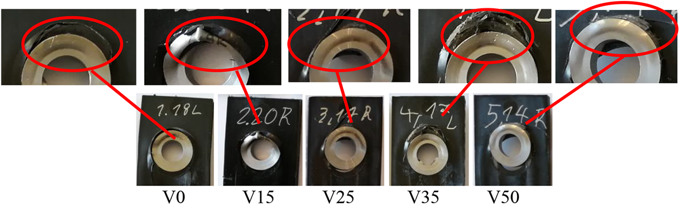
Figure 19 shows examples of damaged specimens in the open hole injection plates with integrated insert type C. Due to the several broken pieces, specimens with 0 vol.% (V0) short-glass failed in a brittle manner. This corresponds to the load-displacement diagram in Figure 17 a). While the test specimens with 0 vol.% (V0) and 15 vol.% (V15) short-glass-fibre content and integrated insert type C failed in the middle of the sample, the remaining samples failed in the load introduction area. This behaviour correlates well with the chart in Figure 18, as the loads of the open-hole plates with insert and 25 vol.% (V25) short-glass-fibre content or more reached the load level of the single insert. The reason for this behaviour is the higher strength of the V25, V35 and V50 materials, which improved the overall performance of the plates.
Conclusions
The current work has demonstrated and discussed the influence of tailored load introduction inserts on the bearing strength of bolt-loaded open-hole injection plates. A varying short-glass-fibre content was used for the injection plates. The load, displacement and the damage behaviour of open-hole plates with reinforcing insert and without insert have been compared and analysed. In addition to the tested reference plates without insert, the single inserts were investigated.
Concluding the so far achieved experimental results, the failure behaviour of injected open-hole plates with different short-glass-fibre content can be significantly improved by integrating a reinforcing insert. In addition to an increase of the load and stiffness, the displacements of the specimens were increased as well. In this way, a residual strength after the first failure and therefore an improved damage tolerance behaviour can be achieved, particularly by using inserts type A and B. However specimens with insert type C failed more abruptly but offered higher tensile strength. Therefore, the choice of the “right” reinforcement insert depends on the requirements of the engineering application. TFP inserts, like insert type A and B, offer individually arranged rovings in the composite as there is no pre-tension of the fibres in the stitching process. Therefore they fail sequentially with a progressive decrease of the force after first damage. Wounded inserts, like insert type C, offer compact ordered tape layers in the loop area, due to the inducted preload in the winding process. In this case the rovings fail together at the same time. Therefore, higher average loads can be reached as well as an abrupt damage behaviour without residual strength can be observed. Regarding the geometrical dimensions of the insert as well as the maximum transmittable force, the Conen model can be used.
Combining the CFRP-Inserts with short-fibre materials showed a better damage tolerance behaviour compared to the behaviour of the single components. While the influence of the short-glass-fibre volume content on the mechanical performance of open-hole plates with insert type B is not evident, the influence with insert type C is visible. Here the maximum performance was achieved with 25 vol.% (V25) short-glass-fibre in the injection area. Higher short-glass-fibre content did not lead to higher performance. In general, the mechanical performance of the insert dominates the load carrying capacity and the failure behaviour of the hybrid composite. In this way, the maximal loads of open-hole plates with an insert reached the load level of the single insert for all types. The displacement at damage initiation (first force peak) is nearly the same for all plates with inserts and lies at the same level of the displacement of the raw inserts, which confirms that the mechanical performance is dominated by the insert properties. Finally, this investigation shows that a small short-fibre volume content is sufficient to reach the maximum performance of the reinforced short-fibre plate which is beneficial for light-weight applications.
Footnotes
Acknowledgements
The presented work was performed within the scope of the project HyPaGear. This research project was founded through budgetary resources from the federal ministry for economic affairs and energy (BMWi) as part of “Zentrales Innovationsprogramm Mittelstand” research programme (ZIM) to whom we would like to express our sincere thanks. Furthermore, we would like to thank our project partner Weberit Werke Dräbing GmbH for manufacturing the injection moulding specimens.
Funding
The author(s) received no financial support for the research, authorship, and/or publication of this article.