
Abstract
In situ microfibrillar ethylene–octene copolymer (POE)/poly(lactic acid) (PLA) composites (MFCs) with different phase morphologies were prepared by controlling the stretching speed and maintaining the weight ratio of POE/PLA of 80/20. Four different stretching speeds were employed to study the effect of PLA microfibrillar morphology on tensile, crystalline, and rheological properties of MFCs. Scanning electron microscopic images revealed that the morphology of PLA phase was strongly influenced by stretching speed. MFCs with highest aspect ratio and smaller diameter of PLA microfibrils were obtained with a stretching speed of 60 rpm. The PLA microfibrils with high aspect ratio had the best reinforcement effect on MFCs. The dynamic rheological properties indicated that the MFCs achieved higher storage modulus and loss modulus at the stretching speed of 60 rpm.
Keywords
Introduction
Ethylene–octene copolymer (POE) has received a lot of attention in the past decades, due to its high elasticity, high elongation, and excellent processing performance.1–6 It is widely used in diverse applications including wires, cables, daily products, and in other industries. Unfortunately, the low strength and low modulus of POE hinders its scope in certain high load-bearing applications.7,8 Hence, there is a need to develop strategies to improve its mechanical performances.
In the past decades, various inorganic fillers were incorporated into the POE matrix to improve its mechanical properties.9–16 Addition of inorganic filler improves the tensile strength and modulus of POE; however, its elongation at break is greatly reduced. Therefore, an effective and facile method to improve the mechanical properties of POE needs to be explored. In recent years, microfibrillar composites (MFCs) were obtained by the in situ formation of microfibrils in an extrusion die with an assembly of laminating-multiplying elements (LMEs).17–21 Compared to inorganic filler-reinforced polymers, it is easier for the reinforcing component to disperse in the MFCs, since LME can induce stronger shearing and drawing forces on the polymer melt. The better reinforcement effect is the result of weaker agglomeration and the smaller diameter of in situ formed microfibrils.22,23
There are relatively fewer reports on the preparation of MFCs using thermoplastic elastomer as the matrix. We fabricated in situ microfibrils reinforced thermoplastic elastomer composites using LMEs.24–27 The MFCs, based on POE and poly(trimethylene terephthalate) (PTT), were obtained by multistage stretching extrusion with LMEs. The PTT microfibrils were found to have more effect on the mechanical properties as compared to PTT particles. In our previous work, poly(lactic acid) (PLA) was chosen as the microfibrillar phase to reinforce POE matrix; since PLA has higher tensile strength and is easy to process and form fibers, we found that the number and the length of PLA microfibrils were apparently enhanced with the increasing PLA content, and the MFCs had better tensile strength and modulus when the weight ratio of POE/PLA is 80/20; the related research work will be published soon. 28 As a part of an ongoing work on a series of in situ microfibrillar POE/PLA composites (MFCs), we fixed the weight ratio of POE/PLA (80/20) and constructed PLA microfibrils with different morphologies by controlling the stretching speed of the polymer melt after it exits the die. The effects of PLA microfibrillar morphology on tensile properties, crystallinity, and rheological properties of MFCs will also be discussed.
Experimental section
Materials
POE (trade name of ENGAGE 8200), which had a melt flow index of 55.0 g/10 min at 190°C and density of 0.87 g cm−
3
, was purchased from Dow Chemical Company (Midland, USA). PLA (trade name of 4032D), with
Specimen preparation
PLA was dried at 80°C under vacuum for 12 h, prior to extrusion. It was then extruded along with POE in a weight ratio of 20/80 using a multistage stretching extrusion system, equipped with 5 LMEs and a twin-screw extruder (length–diameter (L/D) = 40/1, screw diameter = 30 mm), and the roller’s diameter of the tractive device is 30 cm. The temperature of twin-screw extruder was 30°C in the feed section, whereas the temperatures of all other zones were 200°C and the screw speed was 250 rpm. After the POE/PLA melt flowed from the extruder die, the extrudate was further stretched and cooled using a tractive device to obtain MFCs, wherein the stretching speed was fixed at 40, 50, 60, or 70 rpm (scheme in Figure 1). The composites were denoted as M-40, M-50, M-60, and M-70, based on their stretching speed.
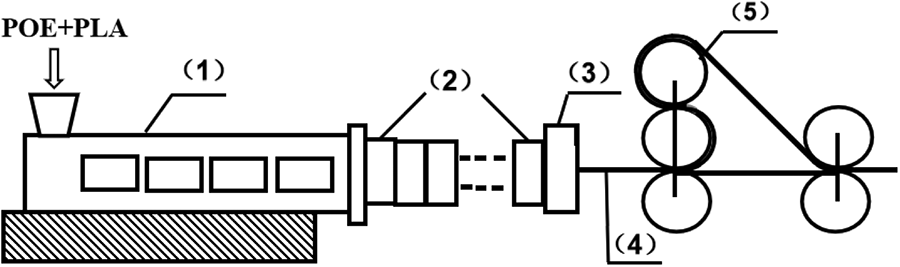
Scheme depicting the multistage stretching extrusion system: (1) twin-screw extruder, (2) laminating-multiplying elements, (3) exit die, (4) polymer melt, (5) tractive device and water cooling block.
Scanning electronic microscopy (SEM)
The morphologies of MFCs phases and structures of PLA microfibrils were studied by SEM. The extruded sheets of four samples were quenched for 6 h in liquid nitrogen (N2) and cryo-fractured along the extrusion direction and vertical extrusion direction. To get a better insight of PLA microfibrillar structure, the extruded MFCs sheets were immersed in xylene at 80°C for 24 h, wherein the POE matrix was etched away leaving the PLA microfibrils exposed. Field-emission SEM (Quanta 250 FEG) was used to explore the morphologies of the MFCs after all the specimens were sputter-coated with gold.
Mechanical property testing
The mechanical properties of the specimens were tested on an MTS CMT6104 model tension machine (China) at a rate of 500 mm min−1 in accordance with ISO 37-2005. Dumbbell-shaped specimens with dimensions of 75 × 5 × 0.6 mm (length × width × thickness) were prepared from the extruded POE/PLA sheets along the extrusion direction. Each specimen was tested five times under the same conditions and the average value was presented.
Differential scanning calorimeter (DSC)
The crystallization and melting behaviors of MFCs were studied by DSC (TA Instrument Model Q10). Samples of MFCs, each weighing 6–7 mg, were derived from the extruded sheets. All measurements were carried on under N2 atmosphere at a heating rate of 10°C min−1 from 20°C to 200°C. The crystallinity of POE was calculated from the DSC data using the following equation:
The crystallinity of PLA was obtained from DSC data using the following equation:
In equations (1) and (2),
Rheological measurements
The rheological behaviors of MFCs were studied by rheometry (MARS60, Haake), using parallel-plate geometry with a diameter of 25 mm. The MFCs were compression molded at 125°C into sheets of 2 mm thickness and 25 mm diameter before testing. The rheological behaviors were tested with 3% strain amplitude and frequency range from 0.1 rad s−1 to 100 rad s−1. The temperature was set constant at 130°C to prevent the melting of PLA microfibrils.
Results and discussion
Morphological analysis
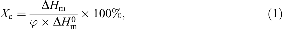
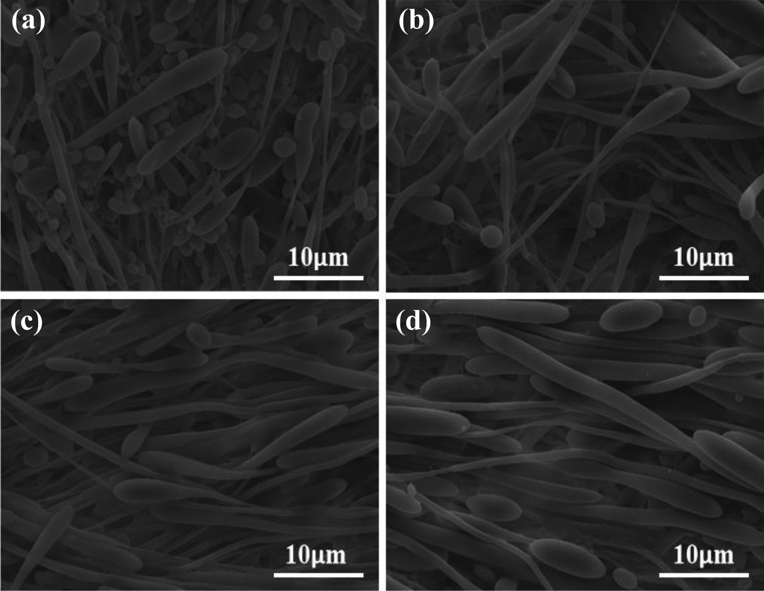
The processing conditions during the preparation of in situ microfibrillar composites affect the morphology of microfibrils.22,23,31 Figures 2 and 3 show the fractured morphologies of PLA microfibrils in MFCs along the extrusion direction and direction vertical to extrusion at different stretching speeds, respectively. The PLA phase in Figure 2 appeared as either short rod-shaped or long PLA microfibrils in the POE matrix, which was oriented along the extrusion direction. The L/D ratios of most of the PLA microfibrils were low for M-40 sample, whereas diameters of PLA microfibrils were relatively high. This could be attributed to the difficulty in melting of PLA to undergo deformation under the weaker stretching action. With increase in stretching speed, high aspect ratio for PLA microfibrils was observed in Figure 2(c) and (d). With high stretching speed (60 rpm, 70 rpm), tension to deform the PLA melt along the stretching orientation was high. It can be seen from Figure 3 that when the MFCs were cryo-fractured along the direction vertical to extrusion, most of PLA microfibrils were pulled out from POE matrix leaving many holes. This occurred due to the poor interfacial adhesion between PLA microfibrils and POE matrix.
The morphologies of PLA microfibrils in MFCs along the extrusion direction: M-40: 40 rpm, (b) M-50: 50 rpm, (c) M-60: 60 rpm, (d) M-70: 70 rpm.
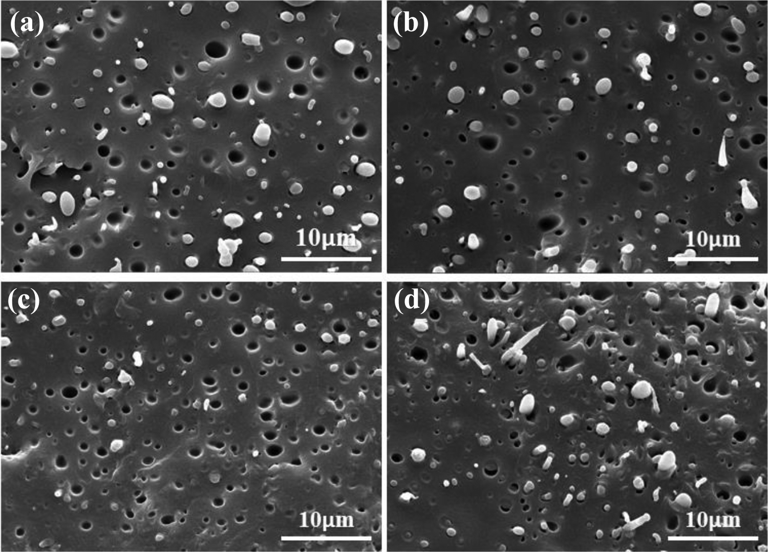
The morphologies of PLA microfibrils in MFCs along the direction vertical to extrusion. (a) M-40: 40 rpm, (b) M-50: 50 rpm, (c) M-60: 60 rpm, (d) M-70: 70 rpm.
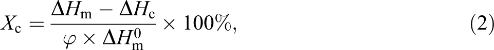
To get clear insight of the structures of PLA microfibrils under different stretching speeds, the POE matrixes were etched away in hot xylene. The morphologies of PLA microfibrils are shown in Figure 4 and their corresponding diameter distributions are shown in Figure 5. It was clearly evident in case of M-40 sample that more of PLA phase was in the form of short rod-shaped microfibrils, with an average diameter of 0.76 μm. With increase in stretching speed, the number of longer PLA microfibrils increased. The average diameter of PLA microfibrils decreased initially and then increased and the size distribution of microfibrils became narrower. When the stretching speed was further increased to 60 rpm in case of M-60 sample, the average diameter was reduced to 0.66 μm. However, it increased to 0.68 µm when the stretching speed was 70 rpm. This can be explained on the basis that stronger stretching action generates higher elongation flow along the stretching direction, causing the PLA melt to stretch. 24 Hence, the average diameter of microfibrils was decreased. With increase in stretching speed to a certain point, the elongated PLA melt could not withstand the large extensional force. They were then broken into smaller entities which caused reduction in their aspect ratio and increase in average diameter.32,33
Morphologies of the PLA microfibrils after etching off POE matrixes. The stretching speeds were (a) M-40: 40 rpm, (b) M-50: 50 rpm, (c) M-60: 60 rpm, (d) M-70: 70 rpm.
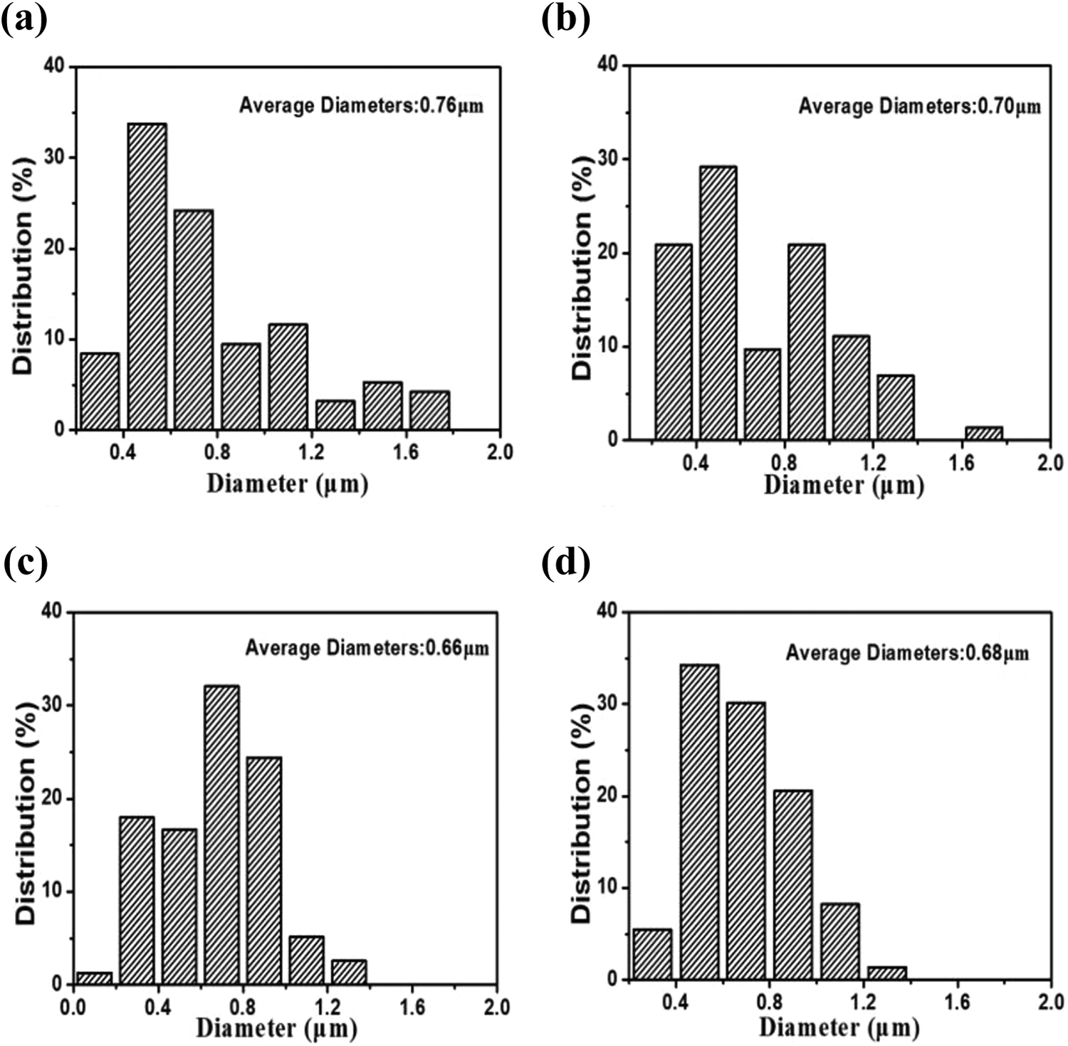
Distribution of diameters of PLA microfibrils. The stretching speeds were (a) M-40: 40 rpm, (b) M-50: 50 rpm, (c) M-60: 60 rpm, (d) M-70: 70 rpm.
Mechanical properties of MFCs
The tensile properties of MFCs depended on the phase morphologies of microfibrils. The PLA microfibrils showed different morphologies for in situ microfibrillar POE/PLA composites at different stretching speeds. The stress–strain curves are shown in Figure 6, wherein due to the limited distance between two crossheads, ultimate ruptures for four samples could not been achieved.
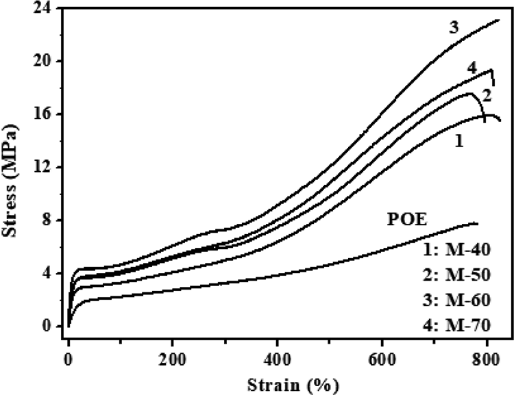
Stress–strain curves of POE and MFCs stretched at a crosshead speed of 500 mm min−1.
From Figure 6, it was evident that the stress–strain curves of MFCs with different stretching speeds were similar. The tensile strength and tensile modulus of POE was lower than that of all MFCs; when the stretching speed increased from 40 rpm to 50 rpm, there was a slight increase in the tensile strength and also tensile modulus for M-50 sample. The M-60 sample showed maximum tensile strength and tensile modulus, and the stress was 20.1 MPa at a strain of 700%, which corresponded to 39.6% increase compared to that of M-40. This suggested that the PLA microfibrils could act as reinforcement for the POE matrix. The tensile properties decreased with further increase in stretching speed. With increase in stretching speed, the tensile strength and modulus of MFCs increased initially and then decreased. This was due to the fact that the average diameter of PLA microfibrils decreased initially and then increased with the stretching speed. The M-60 composite with larger and smaller diameters of PLA microfibrils showed better reinforcement for MFCs.
Thermal properties of MFCs
The melting behaviors of PLA microfibrils and POE matrixes in the MFCs were studied. The melting behaviors of the MFCs, obtained with four different stretching speeds, are shown in Figure 7. The partial DSC data of MFCs are presented in Table 1. For the M-40 composite, the degree of crystallinity of POE was 2.8%. With increase in stretching speed, a slight increase in the degree of crystallinity of POE was observed. There are two factors responsible for this behavior. Accordingly, the extension induced the orientation of POE molecules during the stretching process, which helped to increase the crystallinity of POE. Secondly, the PLA microfibrils acted as nucleating agents for crystallization of POE. The nucleation effect of microfibrils for polymer crystallization was reported for in situ microfibrillar Polypropylene/Polyethylene terephthalate (PP/PET) composites. 28 The degree of crystallinity and Tm value of PLA in M-40 composite were 16.5% and 169.8°C, respectively. When the stretching speed was increased to 60 rpm, the degree of crystallinity and Tm of PLA increased to 21.7% and 171.7°C, respectively. This corresponded to a 5.2% increase in crystallinity degree of PLA. The increase in degree of crystallinity and Tm of PLA could be ascribed to the induction of extensional field. With further increase in stretching speed to 70 rpm for the M-70 composite, the degree of crystallinity decreased significantly and there was a slight decrease in the Tm value, since the excessive tensile stress destroyed a portion of the crystalline structure of PLA.
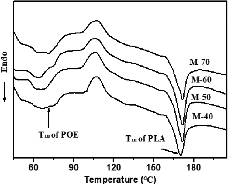
DSC curves during first melting of MFCs with different stretching speeds.
DSC data of MFCs with different stretching speeds.
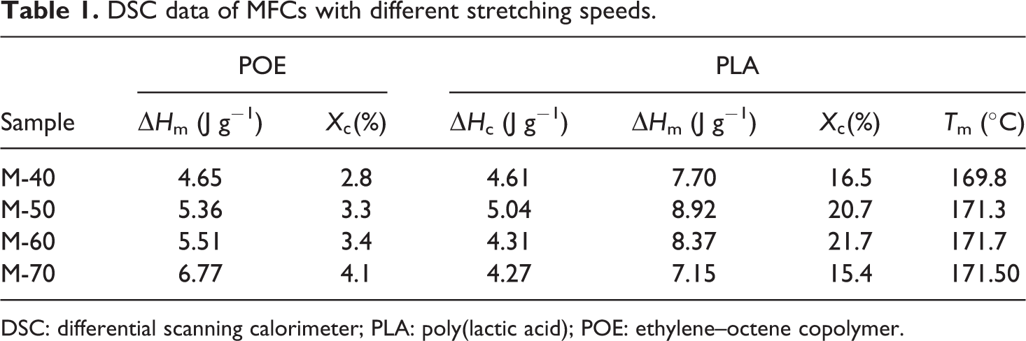
DSC: differential scanning calorimeter; PLA: poly(lactic acid); POE: ethylene–octene copolymer.
Dynamic rheological properties of MFCs
Dynamic rheological properties reflect the morphological evolution of dispersed phase in the polymer matrix, as the viscoelastic properties of polymer blends depend on its phase morphology. 25 The Tm of PLA microfibrils was about 170°C based on thermal analysis. Hence, to keep the PLA microfibrils in solid state, the temperature of dynamic rheological experiments was set at 130°C, wherein the POE phase was in melt state at this temperature.
Figure 8 shows the dependence of storage modulus (G′), loss modulus (G″), and complex viscosity (η*) on angular frequency (ω) of POE and POE/PLA MFCs with different stretching speeds. It can be seen from Figure 8(a) and (b) that the G′ and G″ values of all MFCs were higher than that of POE, and the G′ and G″ values increased with increase in ω for MFCs at all four different stretching speeds. Both G′ and G″ also increased when the stretching speed was lower than 70 rpm. The increase in G′ and G″ could be ascribed to the increase in aspect ratio and smaller diameters of PLA microfibrils. M-60 displayed maximum G′ and G″ values, since this sample had the highest aspect ratio and lowest average diameter of PLA microfibrils. Hence, there was a more likelihood of entanglement between the PLA microfibrils with higher aspect ratio and molecular chains of POE. This was consistent with the SEM and mechanical property analyses. There was a slight decrease in G′ and G″ values when the stretching speed increased to 70 rpm for M-70 composite. This could have occurred due to breaking of some of PLA microfibrils resulting in shorter microfibrils under excessive stretching force. The η* value decreased for all MFCs with increase in ω, as shown in Figure 8(c). The melt of MFCs showed shear-thinning behavior induced by shear, which resulted in the orientation of POE molecular chains and PLA microfibrils. The M-60 samples had the highest η* value for the same ω, which implied higher aspect ratio and smaller diameter for PLA microfibrils. This caused more entanglements between PLA microfibrils and POE molecular chains and its relaxation speed was relatively slow.
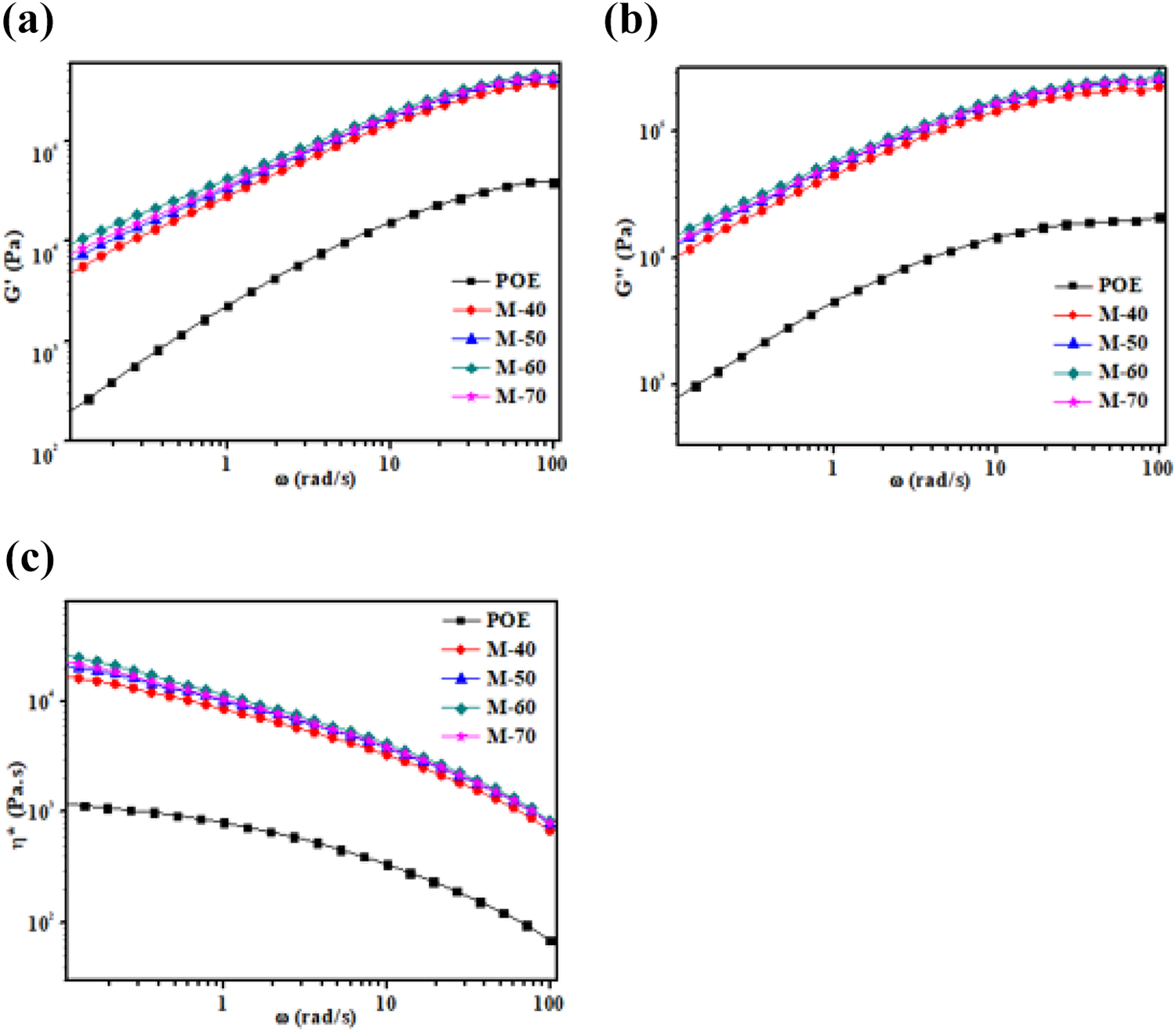
Plots for (a) storage modulus (G′), (b) loss modulus (G″), (c) complex viscosity (η*) of POE, MFCs at different stretching speeds.
Conclusion
Different phase morphologies of in situ microfibrillar POE/PLA composites were obtained by controlling the stretching speed. With increase in stretching speed, the number of longer PLA microfibrils increased. Moreover, the average diameter of PLA microfibrils decreased initially and then increased along with narrowing of size distribution of microfibrils. The MFCs with the highest aspect ratio and smaller diameter of PLA microfibrils were obtained, when the stretching speed was 60 rpm for M-60 composite. The PLA microfibrils with high aspect ratio had the best reinforcement effect on MFCs. With increase in stretching speed, there was a slight increase in the degree of crystallinity of POE and the PLA microfibrils acted as nucleating agents for POE crystallization. The MFCs with higher storage modulus and loss modulus were obtained in case of M-60 composite.
Footnotes
Funding
The author(s) disclosed receipt of the following financial support for the research, authorship, and/or publication of this article: This work was supported by the National Natural Science Foundation of China (21664004), the Guizhou Provincial Science and Technology Project ([2018]2002, [2019]2849, [2019]5639, [2019]5637, [2020]2Y022), and Guiyang Baiyun District’s Science and Technology Plan Project ([2018]5, [2019]23, [2019]20).