
Abstract
To improve the performance of thermoplastic composite joints and reduce the weight of joints, glass fiber (GF)/polypropylene (PP) thermoplastic composite rivets (GF/PP rivets) were prepared and tensile test and simulation analysis of GF/PP-riveted single-lap joints were carried out. Based on the tensile test, the optimum extension length of GF/PP rod with different diameters was determined by taking the specific joint strength (the ratio of joint strength to the weight of fasteners) as the evaluation index. The effects of the rivet diameter and the thickness of composite laminates on the specific joint strength and the weight reduction of GF/PP-riveted single-lap joints were studied. The joining mechanism and the failure behavior of GF/PP-riveted joints were analyzed by finite element simulation. The experimental results indicate that the specific joint strength of GF/PP-riveted joints decreased with increasing rivet diameter and laminate thickness. For the same specific joint strength, the weight of fasteners at joints could be reduced by 81.4% and 73.9%, respectively, by using GF/PP rivets instead of steel bolts and aluminum blind rivets. The simulation results show that the change of inclination angle of rivet body would cause the change of failure mode of joints.
Introduction
Continuous fiber-reinforced thermoplastic composites have become an important development direction of composites.1,2 Its products have been widely used in many fields such as aerospace, automobile, and electrical appliance. 3 Among them, glass fiber-reinforced polypropylene (GP/PP) composites are widely used in the manufacture of seat skeletons, bumper beams, roofs, and other components due to their low cost, easy processing, and good chemical stability.4–6
Due to the need of structural design, process, inspection, transportation, and maintenance of composites and the limitation of the integral molding process, composite components are inevitably divided into several parts. Therefore, the joining technology is a key component in the application of composites. 7 However, the welding cost of thermoplastic composites is high and the technique is difficult, and the adhesive joint of thermoplastic composites requires extremely strict and complex surface treatment. 8 The use of metallic fasteners will significantly increase the weight of joints and may cause electrochemical corrosion. 9 When an aircraft is struck by lightning, the metallic fastener may also become a safety hazard. Because the metallic fastener may form an ignition source, which could be catastrophic around the fuel tank. 10 Therefore, in recent years, composite fasteners have attracted people’s attention, which have lower density and better material matching than metallic fasteners. 11
Ueda et al. 12 prepared GF- and carbon fiber-reinforced nylon composite rivets by the blended yarn braiding method and compared the composite rivet with metallic fasteners by the tensile test of single-lap joints. The results showed that the specific joint load of composite rivets was higher than that of metallic fasteners. Pouliot Laforte et al. 13 joined carbon fiber-reinforced epoxy matrix composites with carbon fiber-reinforced nylon rivets. The effects of heating temperature and time on the properties of the base material were studied by combining experiments with finite element simulations. Starikov and Schön 14 compared the fatigue performance of composite-bolted joints with that of titanium alloy bolted joints. The results showed that the fatigue resistance of composite bolted joints was lower than that of titanium alloy bolted joints due to the low cyclic shear resistance of composite bolts. Hu et al. 15 carried out experiments and finite element simulation analysis on the shear property of 3D-braided composite straight pin fastener and established a set of strength analysis method for 3D-braided composite. The results showed that the proposed strength analysis method was effective in predicting the macroscopic strength properties of 3D-braided composites.
From the existing research results, most of the composite fasteners were fabricated by the braiding method, and the process was complicated. And there are few reports about the application of composite fasteners in thermoplastic composite structures. Therefore, in the present study, GF/PP rod was made of thermoplastic prepreg by pultrusion. After inserting the rod into laminates of the same material system, the reserved extension rod was processed into a shape similar to the end of a metallic rivet with flat head, and the GF/PP rivet was prepared. And in order to maximize the joining performance of GF/PP rivets, a new type of GF/PP-riveted joint was formed by bonding the rivet head to the laminate. Based on the tensile test of single-lap joint, the optimum extension length of GF/PP rods with different diameters was studied and the effects of the rivet diameter and the laminate thickness on the performance of GF/PP-riveted joints were analyzed; by comparing GF/PP rivets with metallic bolts and metallic rivets, the effects of the rivet diameter and the laminate thickness on the advantage in weight reduction of GF/PP rivets were studied; the finite element model for tensile test of GF/PP-riveted single-lap joints was established in ABAQUS/Explicit, and the joining mechanism and the failure behavior of joints were deeply analyzed.
Experimental
Materials
The thermoplastic prepreg (sourced by Shanghai Genius Advanced Material Co., Ltd, China) used in this study is continuous E-glass fiber-reinforced polypropylene (E-GF/PP). The nominal thickness is 0.3 mm. The GF content is 60% by weight. The areal weight is 450 g m−2. The width is 50 mm. The metallic bolts (sourced by Shanghai Huatai Machinery Co., Ltd, China) used in this study are alloy steel and metallic rivets (sourced by Shanghai Huatai Machinery Co., Ltd) are aluminum blind rivets.
Preparation of GF/PP laminates and GF/PP rods
GF/PP laminates were prepared in a flat vulcanizing machine using the consolidation procedure provided by the supplier. The specific consolidation procedure was as follows: the heating rate was 5°C min−1, when the temperature reached to 200°C, 1.5 MPa pressure was applied and kept for 20 min, the cooling rate was 10°C min−1. The laminates were stacked orthogonally and symmetrically. In order to minimize the damage to the laminate in the drilling, diamond bit was used to drill holes in laminates. The diameter of the rivet hole in GF/PP-riveted joints and blind-riveted joint was 0.2 mm larger than that of rivets.
The prepreg tape with a width of 50 mm was cut to 2–3 mm by using a laboratory-made prepreg slitter. The GF/PP rods were prepared by the laboratory-made thermoplastic composite pultrusion device, the diameters of the rods were 3, 4, and 5 mm, respectively. The pultrusion device is shown in Figure 1. Under the action of the guide device, the prepreg tape passed through the preheating furnace at a certain speed in a preset arrangement. When the prepreg tape was brought into the die zone, the radial pressure was generated during the consolidation process due to the change of die size. Because of the existence of radial pressure, the prepreg could obtain secondary impregnation and obtain the required cross-section shape. In addition, the excess resin or bubbles generated during the pultrusion process could also be eliminated from the die in reverse. Finally, the rod was shaped by the cooling die. Figure 2 shows three GF/PP rods with different diameters.
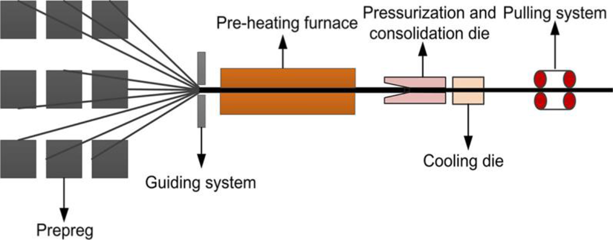
Diagrammatic sketch of pultrusion device for GF/PP rod.
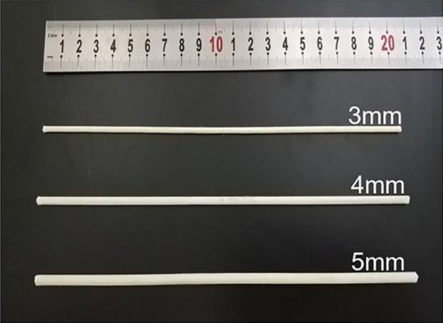
Three GF/PP rods with different diameters.
Preparation of single-lap joints
The prepared rod was inserted into the GF/PP laminate, and a certain length was reserved at both ends. Based on the characteristics of thermoplastic composites that can be processed repeatedly by heating, the reserved rods at both ends were heated and pressurized by a laboratory-made hot-pressing device. Figure 3 is a schematic diagram of the preparation of GF/PP-riveted single-lap joints. The specific process was as follows: the temperature of heating die is 200°C, after heating the rod for 30 s each time, the heating die was lowered by 1 mm until the rod was gradually dispersed and contacted with the laminate. When the dispersed rod was in contacted with the laminates, the pressure of 0.4 MPa was applied and kept for 100 s, the rivet head and the laminate were bonded by the molten resin and then cooled at 10°C min−1. After cooling, the GF/PP-riveted single-lap joint was prepared. The GF/PP rivet is divided into two parts, one is the rivet head, that is, the part bonded with the laminate, and the other part is the rivet rod. When the heating time reaches 100 s, the fibers at the rivet head can be well dispersed. Therefore, the rivet head is regarded as a circle whose radius is the extension length of the rod.
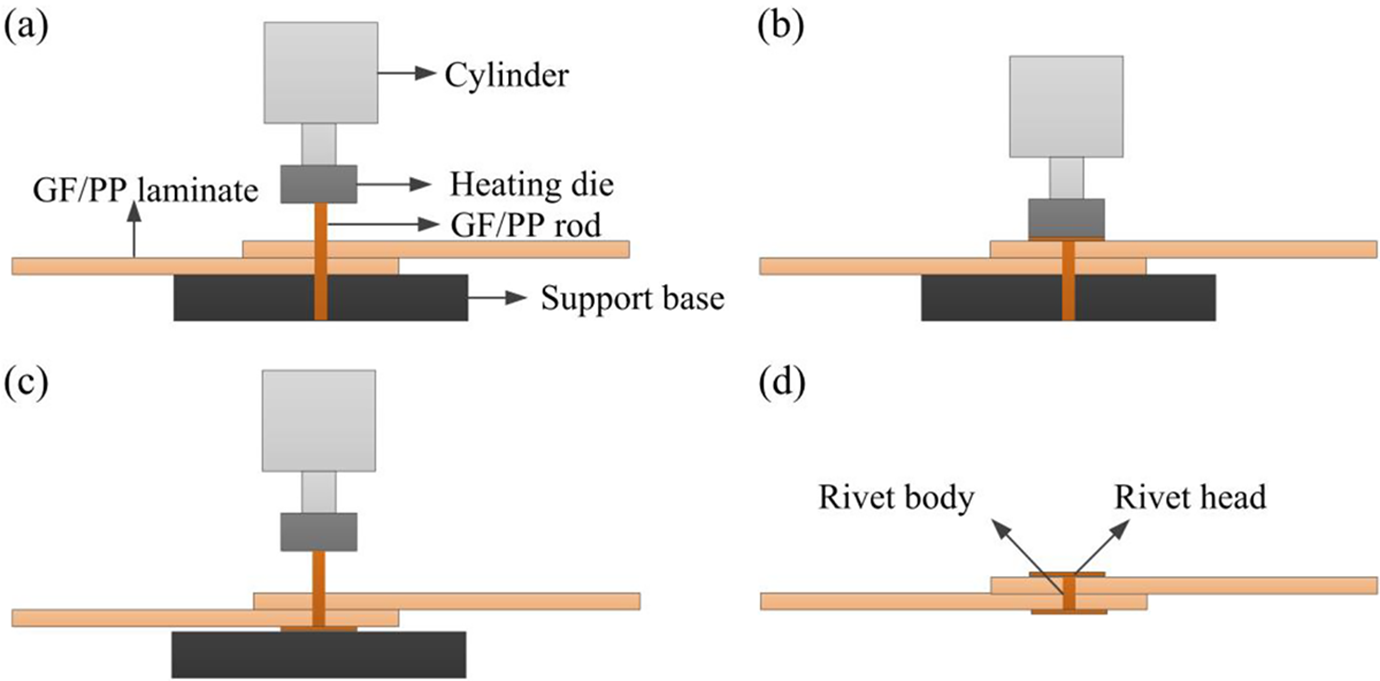
Schematic diagram of the preparation of GF/PP-riveted single-lap joints: (a) die contact GF/PP rod, (b) heat preservation and pressure maintenance, (c) repeat at the other end, and (d) the GF/PP-riveted single-lap joint.
In order to study the effect of the extension length of GF/PP rods on the failure mode and the specific joint strength of GF/PP-riveted single-lap joints and determine the optimum extension length of rod with different diameters, nine groups of specimens were prepared (see Table 1). The configuration of specimens and the specimen with different extension length of rod are shown in Figure 4. The rivet diameter of the specimen shown in the figure is 5 mm. In Figure 4, W is the width of the specimen; D is the diameter of the rivet hole; R is the radius of the rivet head; E is the edge distance; t is the laminate thickness. The value of E/D and W/D of the nine groups of specimens was 6 and 8, respectively. The laminates of the specimen were all thinner laminate with a thickness of 2.4 mm.
Parameters of GF/PP-riveted single-lap joints.
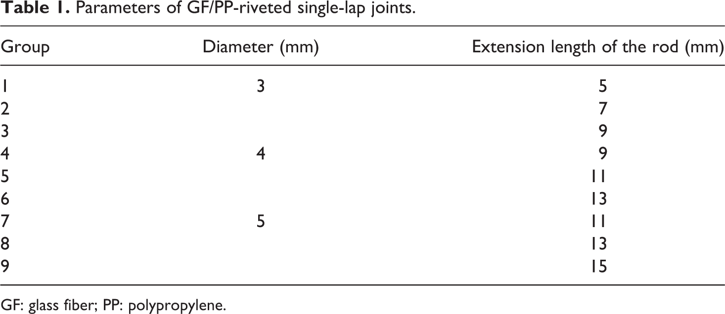
GF: glass fiber; PP: polypropylene.
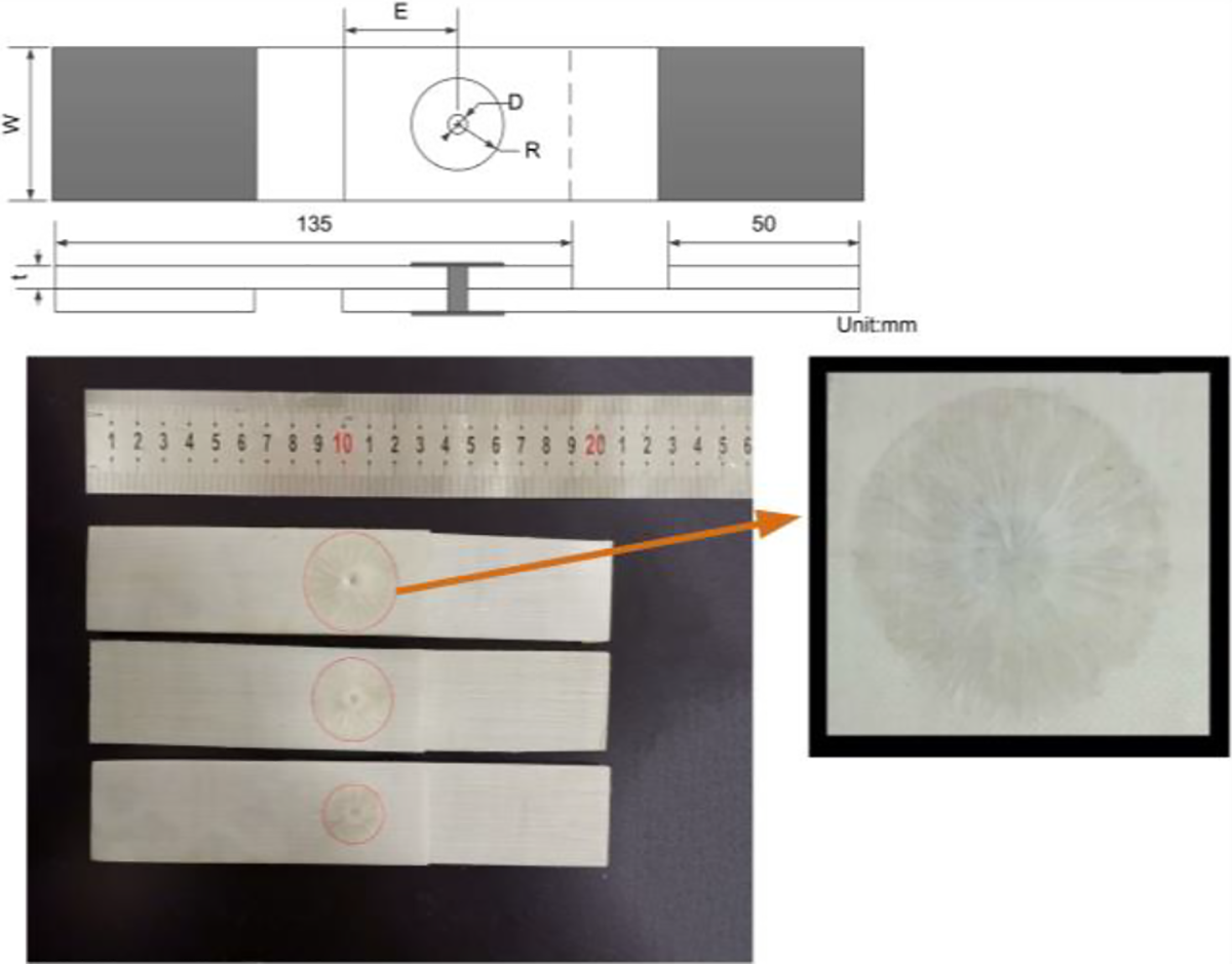
Configuration of specimens and the specimen of GF/PP-riveted joints with different extension length of rods.
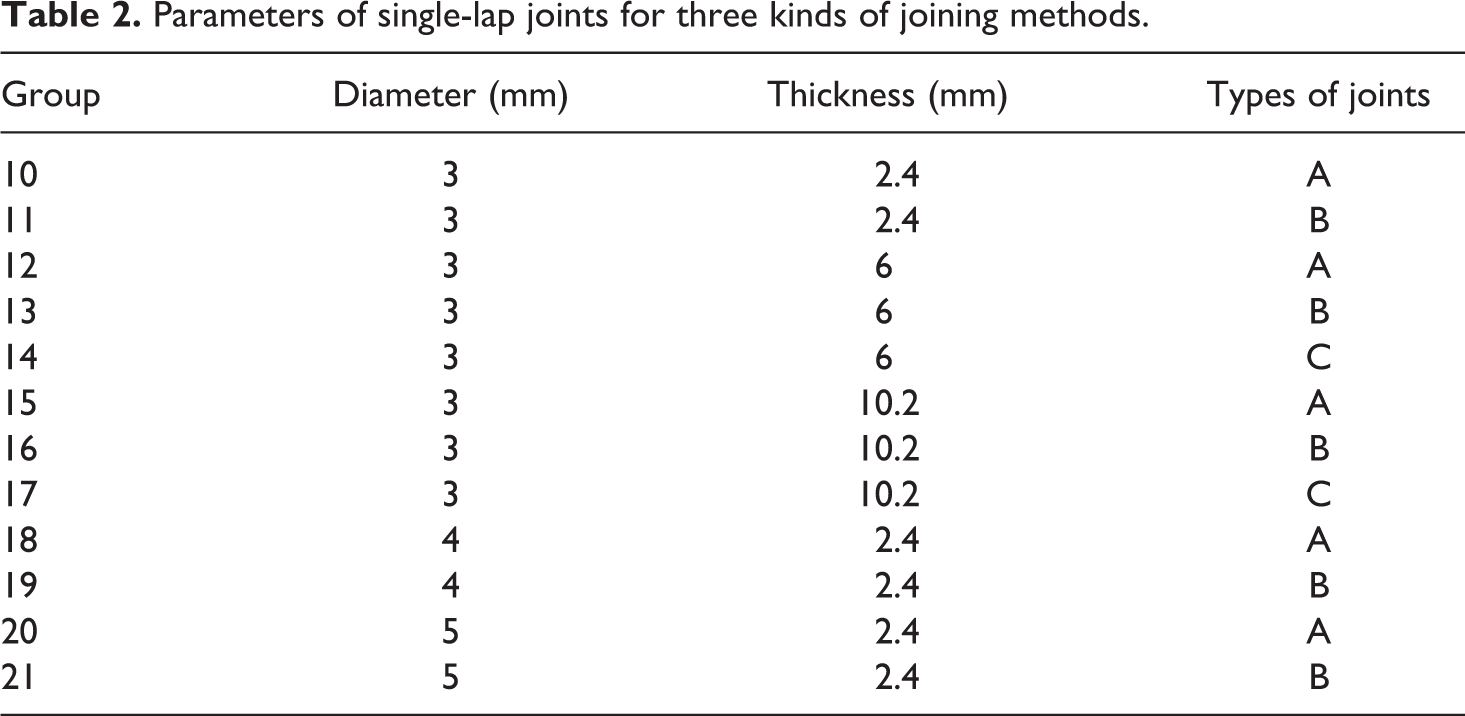
The nine groups of specimens prepared in Table 1 can not only determine the optimum extension length of GF/PP rod but also further analyze the effect of rivet diameter on the specific joint strength of GF/PP-riveted joints. Then, in order to study the effect of different laminate thickness on the specific joint strength of GF/PP-riveted joints and to study the effect of rivet diameter and laminate thickness on the advantage in weight reduction of GF/PP rivets when compared with steel bolts and aluminum blind rivets, 12 groups of specimens were designed on the basis of Table 1 (see Table 2). Among them, A represents bolted joints, B represents blind-riveted joints, and C represents GF/PP-riveted joints. The strength grades of bolts and nuts were 12.9 and 8.8, respectively, and they were obtained in accordance with ISO 4762, 16 the washers were obtained in accordance with ISO 7089. 17 The aluminum blind rivets in group 16 were customized because of their long lengths, the other aluminum blind rivets were obtained in accordance with ISO 14588. 18 In the test, the length of the steel bolt and the blind rivet was determined according to the laminate thickness. In the 10th, 12th, 15th, 18th, and 20th groups, the lengths of steel bolts were 10, 20, 25, 12, and 16 mm, respectively. In the 11th, 13th, 16th, 19th, and 21th groups, the lengths of blind rivets were 8, 16, 25, 8, and 8 mm, respectively. In order to facilitate the analysis of test results, this article neglected the slight difference of diameter and regarded the three kinds of diameters of steel bolts, aluminum blind rivets, and GF/PP rivets as 3, 4, and 5 mm. The E/D and W/D of bolted joints and blind-riveted joints were the same as those of GF/PP-riveted joints.
Parameters of single-lap joints for three kinds of joining methods.
Tensile test of single-lap joints
In order to calculate the specific joint strength of single-lap joints, the weight of each fastener should be measured before assembly. In bolted joints, the weight was the sum of the weights associated with the bolt, nut, and washers. In blind-riveted joints, the weight of the aluminum blind rivet should not include the weight of mandrel (which was removed during the joining process). In order to minimize the influence of eccentric load on the test results, a shim with the same thickness as the laminate was attached to one side of the clamping end of the specimen. Tensile tests of single-lap joints were performed in accordance with ASTM D5961. 19 The specimens were loaded at a rate of 1 mm/min by a computer-controlled mechanical testing machine with a 10 kN load cell (Shenzhen SANS Testing Machine Co., Ltd., China).
Finite element modeling
In order to analyze the joining mechanism and the failure behavior of the GF/PP-riveted single-lap joint, the commercial finite element analysis software ABAQUS 6.14 was used. Considering that in the ABAQUS/Standard, material degradation and failure often lead to serious convergence problems. Therefore, in this simulation, the tension test of the GF/PP-riveted single-lap joint was regarded as a quasi-static problem, an explicit dynamic solver and ABAQUS user subroutine VUMAT were implemented to simulate the 3D progressive failure behavior of the GF/PP-riveted joint.
Material properties
In the present study, the general 3D Hashin failure criterion 20 and the stiffness degradation rule proposed by Tan 21 were employed to simulate the progressive failure behavior of the GF/PP-riveted single-lap joint. Laminates and GF/PP rivets were simulated by linear, eight-node, 3D, reduced integration elements C3D8R. Cohesive elements (COH3D8) were inserted in two parts of the model. Since the GF/PP-riveted joint was formed by bonding the extension rod to the laminate, cohesive elements were used to analyze the debonding between the rivet head and the laminate.
The strength properties of the cohesive element were measured by interlaminar tensile test and shear tests. Zou et al. 22 found that the interface stiffness of composite was generally between 1 × 10⁵ N mm−3 and 5 × 10⁶ N mm−3. In this article, the interface stiffness was set to 1 × 10⁵ N mm−3 by referring to relevant literature 23 (in this literature, the experimental material used was also thermoplastic composite). The selection of fracture toughness was also referred to the relevant literature. 24 The material used in this literature was GF/PP composite with the same fiber volume fraction as this article.
In this study, the GF/PP rod was made of unidirectional prepreg by pultrusion. During the pultrusion process, due to the heating temperature and the pressure, a weak bonding zone in the rivet body was caused where interface failure was most likely to occur in the tensile test of joints. Therefore, cohesive elements were added to the middle of the rod, just as the Z-pin splitting was simulated in the relevant literature. 25 The properties of the cohesive elements in the center of rod were the same as those of the cohesive elements at the rivet head. The crack initiation was judged by the quadratic stress criterion, the interlaminar crack growth was defined through the critical energy release rate based on Benzeggagh-Kenane mixed mode criterion. 26
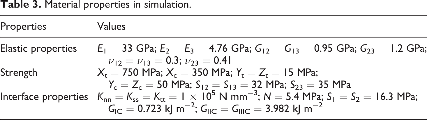
The properties of GF/PP rivets are difficult to be measured by experiments, but rivets and laminates were fabricated of the same prepreg, and therefore the mechanical properties of GF/PP rivets and laminates were assumed to be the same. Some properties of laminates are obtained by experiments, such as E1, E2, E3, S12, S13, S23, and so on. Other properties referred to relevant literature, 27 such as G12, G13, G23, Yt, Yc, and so on. In the literature, the prepreg used in the experiment was also produced by a Chinese company, and its fiber volume content, density, and nominal thickness were the same as the prepreg used in this study. The material properties used in this simulation are summarized in Table 3.
Material properties in simulation.
Establishment of finite element model
In this article, the 3rd and 17th groups of experiments were selected as finite element (FE) model. FE model Ⅰ and FE model Ⅱ were established, respectively, as shown in Figure 5. In the modeling, cohesive elements with thickness of 0.1 mm were inserted between the laminate and the rivet head and tied with the laminate and the rivet head. The thickness of the rivet head was calculated according to the principle that the volume of extension rod was invariable (the volume of extension rod before processing was equal to that after hot pressing), and the thickness of the rivet head in Figure 5 is 0.25 mm. The cohesive elements in the rivet body were created by cutting out a 0.1-mm-thick part inside the rivet body and assigning this part to the material properties of cohesive elements. The friction coefficient of contact surface is very difficult to measure or predict as it depends on the surface conditions of the joining parts. Therefore, in the model, the friction coefficient between the rivet body and the hole was set to 0.1 by referring to relevant literature. 28 In order to improve the calculation efficiency while ensuring the calculation accuracy, the mesh size of the laminate was set as 2.4 mm, and the area around the hole was refined, and the mesh size was 0.625, the mesh size of cohesive element and rivet head was 1 mm, the mesh size of rivet rod was 0.24 mm. One end of the laminate was fixed (U1 = U2 = U3 = UR1 = UR2 = UR3 = 0), and x-displacements were applied at the other end. The load was applied at the amplitude using a smooth step which is recommended in ABAQUS/Explicit to achieve a quasi-static solution, and time step is 0.001 s.
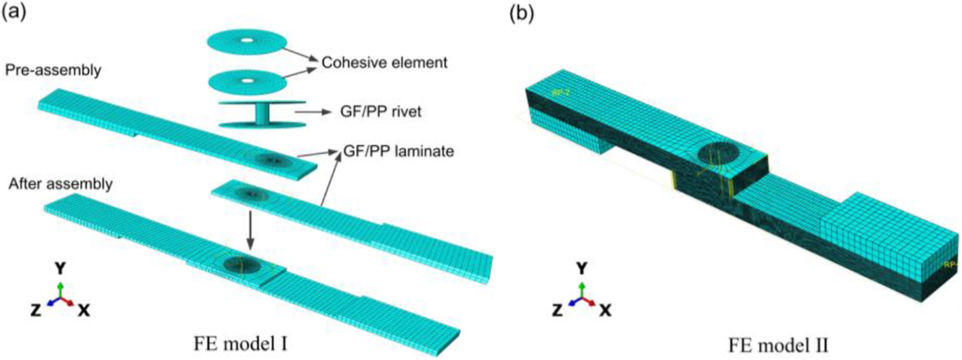
Finite element model for tensile test of the GF/PP-riveted single-lap joint: (a) FE model Ⅰ and (b) FE model Ⅱ.
Results and discussion
Determination of the optimum extension length of GF/PP rod
Tensile test results of single-lap joints with different extension lengths of the GF/PP rod.
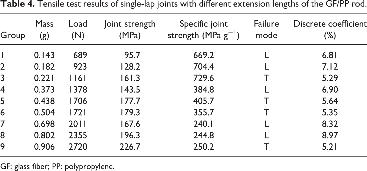
GF: glass fiber; PP: polypropylene.

where σ is the joint strength (MPa), F is the tensile load (N), D is the fastener diameter (mm), t is the laminate thickness (mm), Q is the specific joint strength (MPa g−1), and M is the mass of the fastener (g).
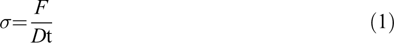
There were two failure modes for GF/PP-riveted joints of three diameters. When the extension length of the rod was short, the bonding force between the rivet head and the laminate was small, so the debonding failure between the rivet head and the laminate occurred during the test. When the extension length of the rod was increased to a certain value, the failure mode of the joint changed to the tension failure at the transition between the rivet head and the rivet body. And at this time, the specific joint strength reached the maximum. Figure 6 shows two failure modes for the GF/PP-riveted single-lap joint with a rivet diameter of 5 mm. As can be seen from Table 4 that when the laminate thickness is 2.4 mm, the optimum extension length of GF/PP rods with diameters of 3, 4, and 5 mm are 9, 11, and 15 mm, respectively. The specific joint strength of joints will decrease when the extension length of the GF/PP rod is lower or higher than this value. In the subsequent test, extension length of GF/PP rod was the optimum length in this test.
Two failure modes of the GF/PP-riveted single-lap joint: (a) debonding failure between the rivet head and the laminate and (b) tensile failure at the transition between the rivet head and the rivet body.
Comparison of load–displacement curves of three joining methods
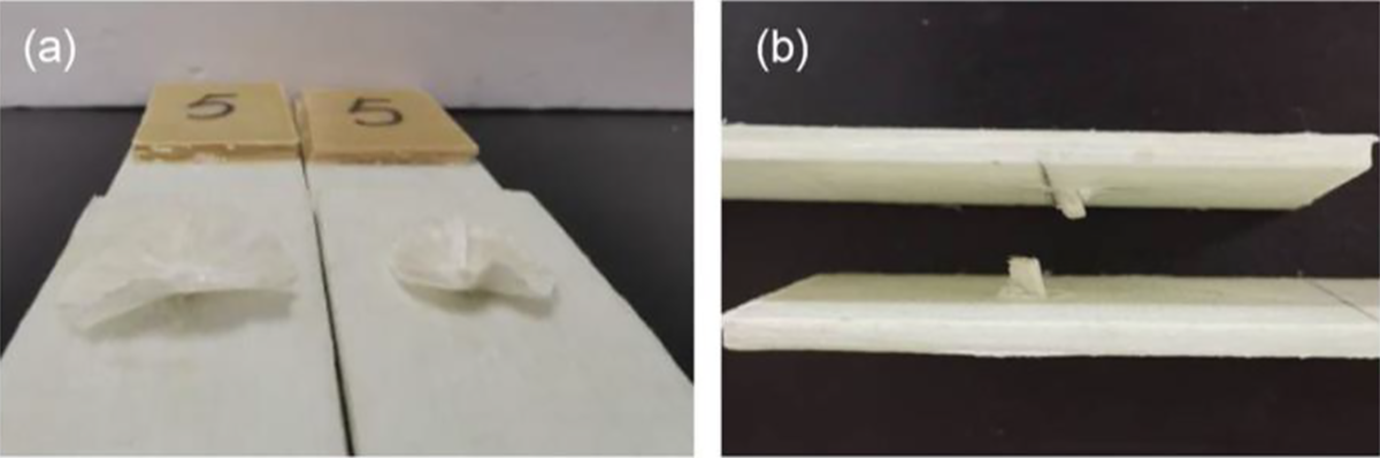
Tensile test results of joints with three joining methods are given in Table 5. In order to analyze the joining mechanism of steel bolted joints, blind-riveted joints, and GF/PP-riveted joints, the typical load–displacement (L–D) curves of the 12th, 13th, and 14th groups of experiments were compared. The results are shown in Figure 7.
Tensile test results of joints with three joining methods.
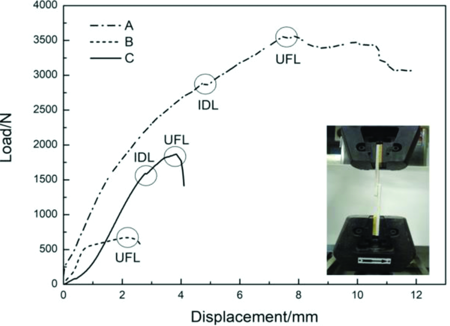
L–D curves of three kinds of single-lap joints.
It can be seen from Figure 7 that the L–D curves of three kinds of single-lap joints are all nonlinear, and stiffness of the steel bolted joint and the blind-riveted joint is obviously higher than that of the GF/PP-riveted joint. The reason is that the elastic modulus of the steel bolt and the blind rivet is significantly higher than that of the GF/PP rivet.29,30 The initial damage of the bolted joint and the GF/PP-riveted joint was caused by the bearing damage of the laminate. However, the initial damage load (IDL) of the bolted joint was higher than that of the GF/PP-riveted joint. This is mainly because the assembly clearance of GF/PP-riveted joints was larger than that of steel bolted joints. The GF/PP rivet would incline immediately when the load was applied. In the GF/PP-riveted joint, the inner side of the laminate was subjected to the bearing stress. However, in the bolted joint, both sides of the laminate were subjected to the bearing stress. Therefore, the stress concentration around the hole was more obvious in the GF/PP-riveted joint, and the inner side of the laminate was damaged in advance, so its IDL value was lower. A knee point is not observed in the L–D curve of the blind-riveted joint. This indicates that the damage develops mainly in the blind rivet, and the laminate is basically undamaged. The failure of the rivet occurred in the blind-riveted joint and the GF/PP-riveted joint, and the bearing failure of the laminate occurred in the steel bolted joint. Therefore, among the three kinds of joints, the load of the bolted joint was the highest, and the joint with hollow aluminium rivet was the lowest.
Effect of the laminate thickness on the performance of GF/PP-riveted single-lap joints
The 3th, 14th, and 17th groups of experiments were selected to analyze the effect of the laminate thickness on the specific joint strength of GF/PP-riveted single-lap joints with a rivet diameter of 3 mm. It can be seen from Tables 4 and 5 that the specific joint strength of GF/PP-riveted joints decreases with increasing the laminate thickness. When the laminate thickness increases from 2.4 mm to 6 mm and 10.2 mm, the specific joint strength decreases by 48.9% and 75.2%, respectively. According to the formula for calculating the specific joint strength, it can be seen that the specific joint strength depends on the joint strength and the weight of fasteners. On the one hand, although the load of GF/PP-riveted joints increased with increasing the laminate thickness, the ultimate failure mode of the joint was always the failure of GF/PP rivets, so increasing the laminate thickness could not correspondingly improve the joint strength. On the other hand, the weight of GF/PP rivets increased with increasing the laminate thickness. Therefore, when the joint strength decreased and the weight increased, the specific joint strength of the GF/PP-riveted joint decreased significantly. It was also found that when the laminate thickness was 2.4 and 6 mm, the failure mode of the joint was the tension failure at the transition between the rivet head and the rivet body. When the laminate thickness increased to 10.2 mm, the failure mode of the joint changed to the shear failure of the rivet body, as shown in Figure 8.
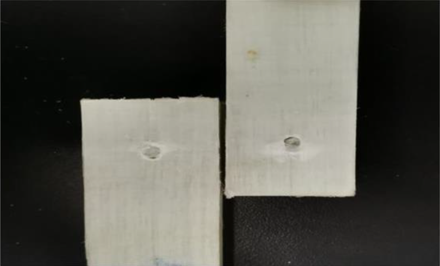
Shear failure mode of the rivet body.
The 3th and 10th–17th groups of experiments were selected to analyze the relationship between the proportion of weight reduction of fasteners at the GF/PP-riveted joint with a rivet diameter of 3 mm and the laminate thickness. The results are shown in Figure 9. The S1 and S2 in the figure, respectively, represent the proportion of weight reduction of fasteners at the GF/PP-riveted joint compared with the bolted joint and the blind-riveted joint when the joint parameters (the fastener diameter and the laminate thickness) are the same. As can be seen from the figure, the maximum S1 can reach 77.9%, and S1 decreases with increasing the laminate thickness. When the laminate thickness increases from 2.4 mm to 6 mm and 10.2 mm, S1 decreases by 10.2% and 24.5%, respectively. The maximum S2 can reach 73.9%, and S2 increases with increasing the laminate thickness. When the laminate thickness increases from 2.4 mm to 6 mm and 10.2 mm, S2 increases by 19.3% and 22.7%, respectively. The changes in S1 and S2 represents the changes in the proportion of the increase in the specific joint strength of the GF/PP-riveted joint compared with the bolted joint and the blind-riveted joint. Although the specific joint strength of the bolted joint and the GF/PP-riveted joint decreased with increasing the laminate thickness, the decreasing trend of the GF/PP-riveted joint was more significant, so S1 decreases with the increase of laminate thickness. It shows that compared with the steel bolt, the advantage in weight reduction of GF/PP rivet is more prominent when the laminate is thinner. The ultimate failure mode of the blind-riveted joint was the shear failure of the rivet body, its load did not change substantially with the increase of laminate thickness, so the specific joint strength decreased significantly with increasing the laminate thickness. Therefore, S2 decreases with increasing the laminate thickness. It shows that compared with the metallic blind rivet, the advantage in weight reduction of GF/PP rivet is more prominent when the laminate is thicker.
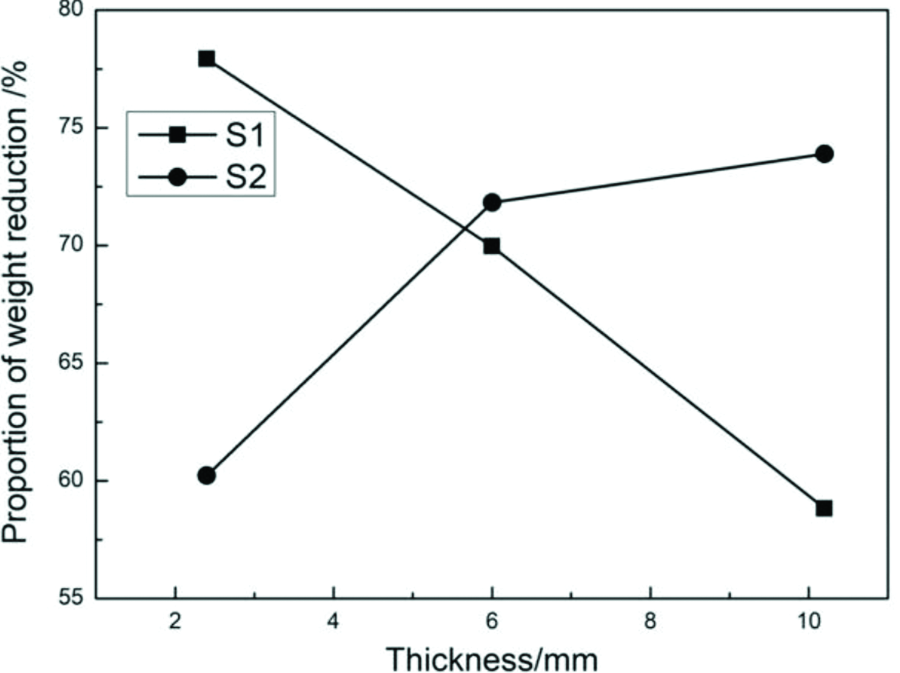
The relationship between the proportion of weight reduction of fasteners at joints and the laminate thickness.
Effect of the rivet diameter on the performance of GF/PP-riveted single-lap joints
The 3th, 5th, and 9th groups of experiments were selected to analyze the effect of the rivet diameter on the specific joint strength of the GF/PP-riveted single-lap joint with a laminate thickness of 2.4 mm. It can be seen from Table 4 that the specific joint strength of the GF/PP-riveted joint decreases with increasing the diameter. When the diameter of the GF/PP rivet increases from 3 mm to 4 mm and 5 mm, the specific joint strength decreases by 44.4% and 65.7%, respectively. Although the joint strength of the GF/PP-riveted joint increased with increasing the rivet diameter, the weight of the GF/PP rivet increased with increasing the rivet diameter and extension length of the GF/PP rod. And the proportion of the increase in the joint strength was less than that of the increase in the weight. Therefore, the specific joint strength of the GF/PP-riveted joint decreased with increasing the rivet diameter. The failure modes of joints in these three groups of experiments were tensile failure at the transition between the rivet head and the rivet body.
The 3th, 5th, 9th, 10th, 11th, and 18th–21th groups of experiments were selected to analyze the relationship between the proportion of weight reduction of fasteners at the GF/PP-riveted joint with a laminate thickness of 2.4 mm and the rivet diameter. The results are shown in Figure 10. As can be seen from the figure, the maximum S1 can reach 81.4%, and S1 does not change significantly with the increase of diameter, and the maximum rate of change is only 4.5%. The maximum S2 can reach 60.2%, and S2 decreases with increasing the rivet diameter. When the diameter of the GF/PP rivet increases from 3 mm to 4 mm and 5 mm, S2 decreases by 12.5% and 28.8%, respectively. Because the specific joint strength of the bolted joint and the GF/PP-riveted joint decreased with the increase of the diameter and the decrease ratio of them was close to each other, S1 has little relationship with diameter. It shows that compared with the steel bolt, the diameter has little effect on the advantage in weight reduction of the GF/PP rivet. And compared with the blind-riveted joint, the specific joint strength of the GF/PP-riveted joint decreased more significantly with the increase of the rivet diameter, so S2 decreases with increasing the rivet diameter. It shows that compared with the metallic blind rivet, the advantage in weight reduction of the GF/PP rivet with a diameter of 3 mm is more prominent.
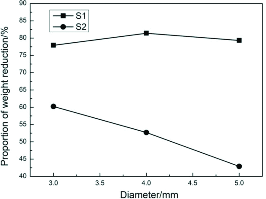
The relationship between the proportion of weight reduction of fasteners at joints and the rivet diameter.
Finite element analysis
In the beginning, some phenomena and results of the tensile test of bolted joints, blind-riveted joints, and GF/PP-riveted joints were analyzed. However, for the new joining method of thermoplastic rivet in this study, it is necessary to establish the corresponding FE model and further analyze the joining mechanism and failure behavior of GF/PP-riveted joints. In this article, the relevant FE models were established by taking the 3th and 17th groups of experiments as examples. Two types of failure modes of GF/PP-riveted joints were involved in the two groups of experiments. Finally, the validity of the FE model was judged by comparing the maximum joining load obtained from the FE model with the maximum joining load measured from the corresponding experiment and comparing the failure mode obtained from the FE model with the actual failure mode.
Progressive damage analysis of FE model Ⅰ
In the FE model Ⅰ, the laminate thickness was 2.4 mm, the rivet diameter was 3 mm, and the length of the rivet body was 5 mm. Figure 11 shows the L–D curve obtained by experiments and simulations. Point A and point B in Figure 11 are the obvious knee point in the L–D curve obtained by experiments and simulations.
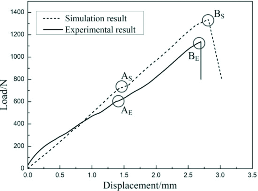
Comparison between simulation results and experimental results.
By comparing the L–D curves, it is found that the ultimate load obtained by simulations is 15.9% higher than the ultimate load obtained by experiments. There are two main reasons for the errors: (1) GF/PP laminates and GF/PP rods were prepared by molding press process and pultrusion process, respectively. The properties of laminates and GF/PP rivets were the same in simulation, so the effects of processing methods on the material properties were neglected; (2) the fiber damage at the rivet head during hot pressing was neglected in the simulation.
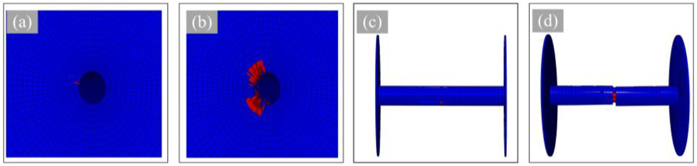
It can be seen from the L–D curve obtained by simulations that when the displacement reaches about 1.5 mm, the first knee point As appears. By observing the damage of the joint at this time, it was found that As was caused by the damage of the laminate, which led to the decrease of the joint stiffness. Similar knee point AE can be seen from the L–D curve obtained by experiments. Due to the presence of the assembly clearance, the GF/PP rivet would incline immediately when the displacement was applied. With the increase of displacement, the bearing stress around the hole increased. The compression damage of the matrix in the inner side of the laminate occurred first. Afterward, the rivet body continued to incline as the load increased, as shown in Figure 12. As fiber compression and matrix tensile/compression continued to evolve, only small amount of fiber tensile failure was recorded. Figure 13 shows the progressive compression damage process of the laminate. When point BE was reached, the end of rivet was damaged and the load dropped rapidly.
Comparison between simulations and experiments of rivet inclination.
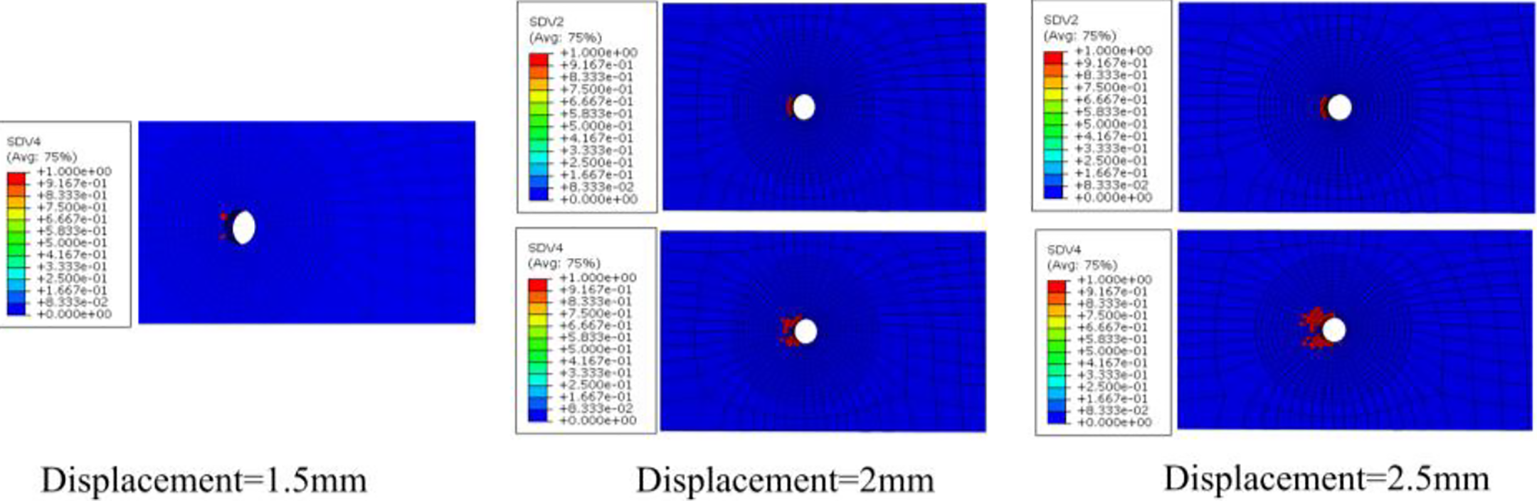
The progressive compression damage process of the laminate.
It can be seen from the experiment and the FE model Ⅰ that the corresponding area of the rivet head would be damaged during the inclination of the rivet body. Taking the upper laminate as the research object, it was found that the bonding area of the lower part of the rivet head bulged obviously, as shown in Figure 14(a). Combined with the stress distribution of cohesive elements at the rivet head, it can be found that the failure modes of cohesive elements in this area were mixed failure modes of type I and type II, and the closer to the center, the greater the proportion of type I. The damage of cohesive elements is shown in Figure14(b). Thus, in the experiment of determining the optimum extension length of the GF/PP rod, the debonding failure at the rivet head would occur in advance when the bonding area between the rivet head and the laminate was small. Therefore, the determination of the optimum extension length of GF/PP rods is the premise to maximize the specific joint strength of GF/PP-riveted single-lap joints.
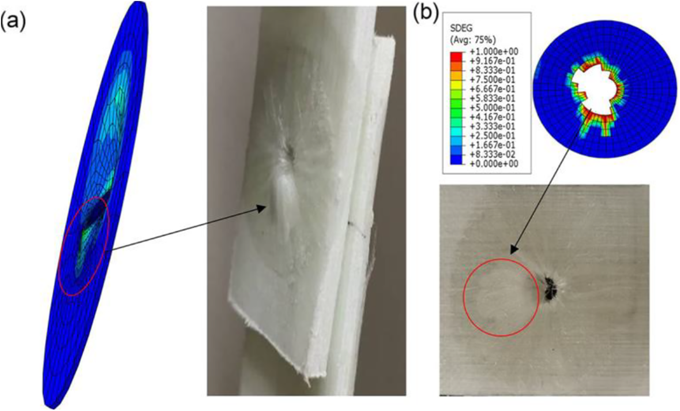
Comparison between simulations and experiments of damage at the rivet head: (a) bulge of rivet head and (b) damage of cohesive elements.
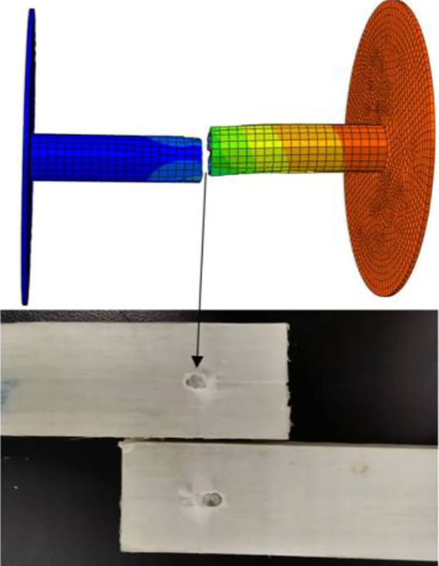
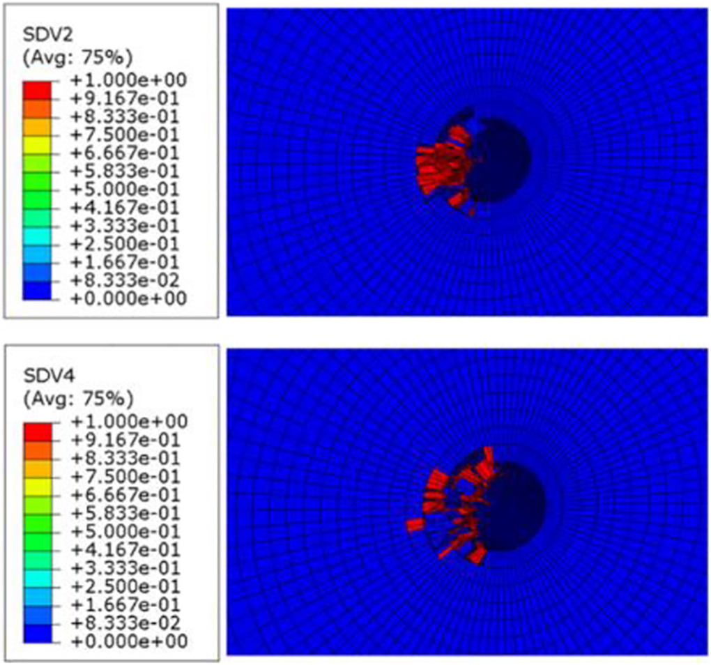
Figure 15 shows the stress distribution of the GF/PP rivet during loading. From the contour of stress distribution, it can be seen that the stress mainly concentrates on the two ends and the middle part of the rivet body. The upper part of the right end of rivet is mainly subjected to tension stress, while the lower part is mainly subjected to compression stress. The stress distribution on the left side is contrary to that on the right side. The upper part is mainly subjected to compressive stress, while the lower part is mainly subjected to tensile stress. The middle part of the rivet body is subjected to shear stress, and the cohesive element in the rivet body is subjected to interlaminar shear stress. Therefore, tensile failure at the transition between the rivet head and the rivet body occurred when the tensile stress at the rivet end exceeded its tensile strength and the shear stress at the middle part of the rivet body did not reach its shear strength, as shown in Figure 16. Figure 17 shows the damage propagation of the cohesive element in the rivet body. As can be seen from the figure, the damage of cohesive elements occurred initially in the middle part. With the increase of load, the damage of cohesive elements on both sides gradually occurred. When the load reached its maximum, the damaged area of cohesive elements reached 50%. Subsequently, the damage of cohesive elements propagated rapidly from both sides to the middle due to the tensile failure at the transition between the rivet head and the rivet body. Finally, when the load reached 1065 N, the output variables (SDEG) of cohesive elements all reached 1.
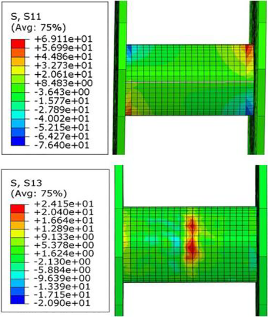
Contour of stress distribution of the GF/PP rivet.
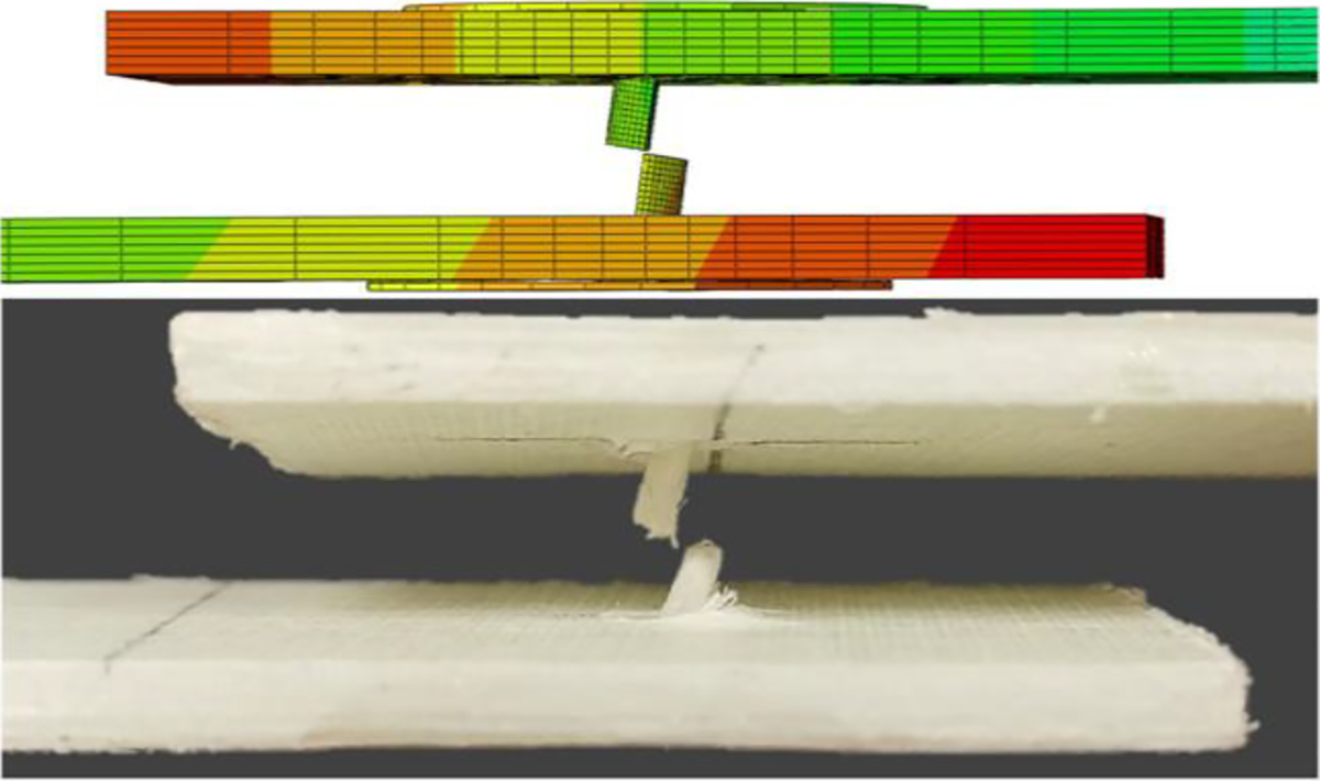
Comparison between simulations and experiments of tensile failure at the transition between the rivet head and the rivet body.
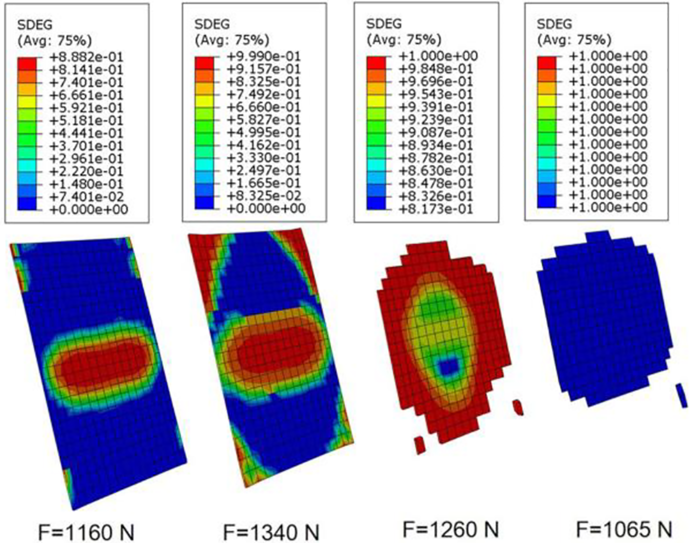
Damage propagation of cohesive elements in rivet body.
Progressive damage analysis of FE model Ⅱ
In the FE model Ⅱ, the thickness of the laminate was 10.2 mm, the diameter of the GF/PP rivet was 3 mm, and the length of the rivet body was 20.6 mm. Figure 18 shows the L–D curves obtained by experiments and simulations. Point X, point Y and point Z in Figure 18 are the obvious knee point in the L–D curve obtained by experiments and simulations.
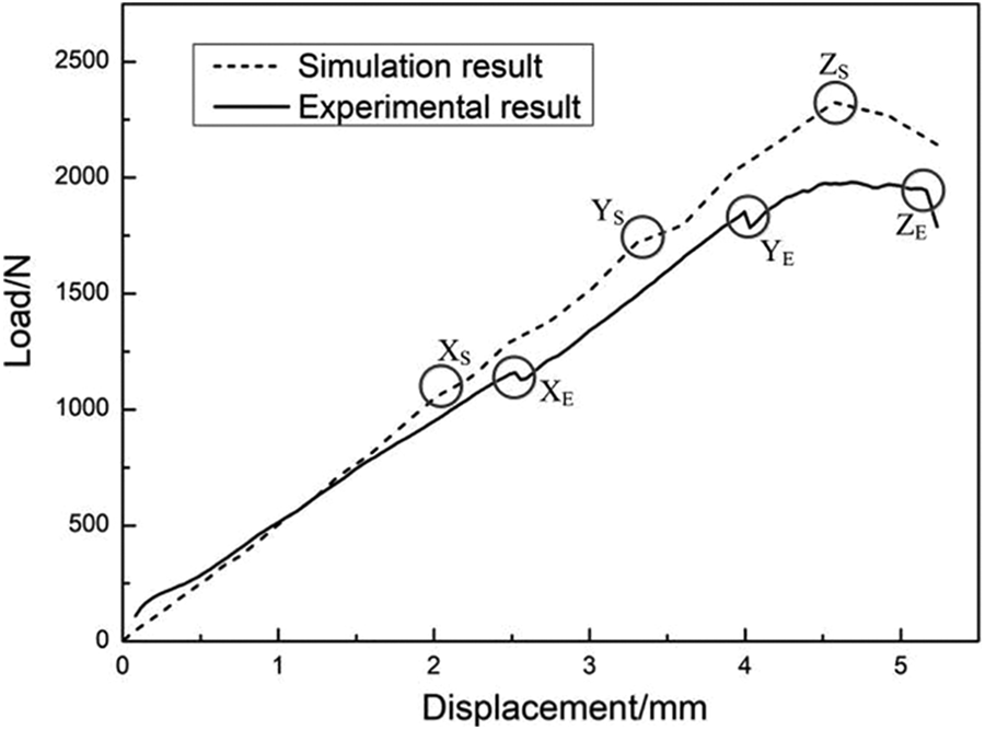
Comparison between simulation results and experimental results.
By comparing the L–D curve, it is found that the ultimate load obtained by simulations is 14.5% higher than the ultimate load obtained by experiments. It was found from the L–D curve obtained by simulations that when the displacement reached 2 mm, the first knee point XS appeared. It was also caused by the initial compression damage of the matrix, as shown in Figure 19(a). Similar knee point XE can be seen from the L–D curve obtained by experiments. When the displacement increased to about 3.5 mm, the second knee point YS appeared. From XS to YS, the maximum bearing stress around the hole increased by 79%, stress concentration around the hole was more obvious. By observing the damage of the joint, it can be seen that at YS point, the laminate was further damaged and the rivet body was initially damaged, as shown in Figure 19(b) (the figure shows the compression damage of the matrix) and Figure 19(c). Similar knee point YE can be seen from the L–D curve obtained by experiments. When the displacement increased to about 4.5 mm, the third knee point ZS appeared. At this time, the damage of rivet body has accumulated to a certain extent, which leads to the reduction of joining load. The damage of rivet body is shown in Figure 19(d).
Progressive damage process of joints: (a) initial damage of the 10.2-mm-thick laminate, (b) damage propagation of the laminate, (c) initial damage of the rivet body, and (d) rivet failure.
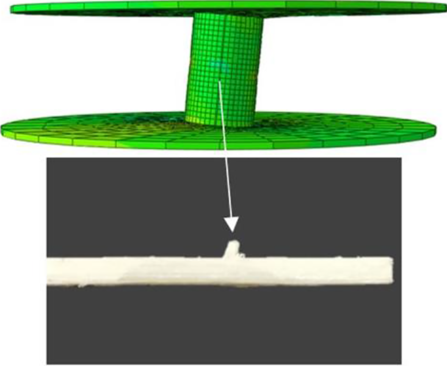
With the increase of laminate thickness, the inclination angle of the rivet body decreased, so the ratio of tensile stress to shear stress of the rivet body changed. The tension stress at the rivet ends and the interlaminar shear stress inside the rivet body decreased correspondingly, while the shear stress in the middle of the rivet body increased correspondingly. Therefore, shear failure of the rivet body occurred when the shear stress in the middle part of the rivet body exceeded its shear strength and the tensile stress at the rivet end did not reach its tensile strength, as shown in Figure 20. Compared with the rivet with length of 5 mm, the damage of cohesive elements in the rivet body with length of 20.6 mm was alleviated. Figure 21 shows the final damage of the 10.2-mm-thick laminate. By analyzing the damage of the laminate, it is found that the damaged area is concentrated in the inner side of the laminate, and the damaged thickness is only 3.3 mm, which accounts for one-third of the total thickness of the laminate. It can be concluded that for the GF/PP-riveted single-lap joint, increasing the laminate thickness cannot significantly alleviate the stress concentration around the hole. The main reason for the increase of tensile load with increasing the laminate thickness is that the length of the rivet becomes longer, which leads to the smaller inclination angle of the rivet body at the same offset displacement, thus delaying or preventing the tension failure at the transition between the rivet head and the rivet body. And no obvious bulge phenomenon was observed at the rivet head in experiments and simulations. Figure 22 shows the damage of cohesive elements at the rivet head. Compared with Figures 14(b) and 22, the damaged area of cohesive elements decreases significantly due to the decrease of the inclination angle of the rivet body. This shows that, the optimum extension length of the GF/PP rod is related to the laminate thickness. With the increase of the laminate thickness, the extension length of rods can be reduced accordingly, so as to further improve the specific joint strength of GF/PP-riveted joints and enhance the advantage in weight reduction of the GF/PP rivet.
Comparison between simulations and experiments of shear failure.
Compression damage of the 10.2-mm-thick laminate.
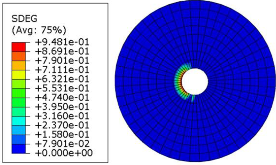
Damage of the cohesive element at the rivet head.
Conclusion
In this article, the optimum extension length of GF/PP rods with different diameters was determined by tensile test of single-lap joints, the effects of rivet diameter and laminate thickness on the performance of GF/PP-riveted joints were studied, and the joining mechanism and the progressive failure behavior of GF/PP-riveted joints were analyzed by finite element simulation.
The optimum extension length of the GF/PP rod increased with increasing rivet diameter and decreased with increasing laminate thickness. When the length of the GF/PP rod was less than the corresponding optimum length, the debonding failure occurred between the rivet head and the laminate; when the length of the GF/PP rod was equal to or greater than the corresponding optimum length, the tensile failure occurred at the transition between the rivet head and the rivet body or the shear failure of the rivet body occurred.
Tensile test results of single-lap joints with three joining methods show that the specific joint strength of GF/PP-riveted joints decreased with increasing rivet diameter and laminate thickness; compared with steel bolts, the advantage in weight reduction of GF/PP rivets was more prominent when the laminate was thinner, the weight of fastener at joints could be reduced by 81.4%, while the rivet diameter had little effect on the advantage in weight reduction of GF/PP rivets; compared with aluminum blind rivets, the advantage in weight reduction of GF/PP rivets was more prominent when the laminate was thicker and the rivet diameter was smaller, the weight of fastener at joints could be reduced by 73.9%.
The L–D curves and the failure modes obtained from the numerical analysis are shown to be in a good quantitative and qualitative agreement with experimental results. The numerical analysis results show that the change of inclination angle of rivet body would cause the change of failure behavior of GF/PP-riveted joints.