
Abstract
A general testing approach is presented via a fracture mechanics study on the interfacial delamination behavior in overmolded composite materials using a variant of the double cantilever beam (DCB) geometry. Overmolding, a common injection molding process, is used to fabricate asymmetric DCB test specimens with Lexan™ 3414 resin overmolded onto commercially available TenCate Cetex® FST woven glass fiber/polycarbonate laminates. An analytical beam theory model is employed to partition the planar fracture modes at the overmold interface into mode I and mode II components, which are functions of material properties and relative beam thicknesses. Specimen curvature measurements are integrated into the beam theory model to estimate the residual stress effects on fracture mode mixity. We use the overmold thickness as a tunable variable to control fracture mode mixity, and target near mode I fracture conditions, where we find mode I fracture energy (GIc) values of approximately 1 kJ/m2. Fiber bridging across the failure interface is observed, which is not expected at the nominal polymer/polymer overmold interface. Complementary scanning electron microscopy images of the failure surfaces indicate crack initiation at the overmold interface, followed by a change in locus of failure to the nearby polymer/glass fiber interface in the top layer of the composite laminate. Fiber bridging is observed in all specimens tested over a modest range of mode mixity, including specimens modified to the single leg bending geometry, suggesting that the polymer/glass interface is more susceptible to crack propagation than the desired overmold interface, which likely derives its strength from molecular interdiffusion during the overmolding process.
Keywords
Introduction
Overmolding is an increasingly common injection molding technique used to manufacture hybrid composite components consisting of multiple materials.1–3 The overmolding manufacturing process typically involves the pressurized delivery of a molten thermoplastic polymer or synthetic resin into a shaped mold, which contains inserts of other, usually structural or electronic, materials. Overmold and insert materials may be of similar or dissimilar composition and type, requiring the formation of interfacial bonds between different materials (e.g. polymer/polymer, polymer metal, polymer/fiber-reinforced plastics (FRP), etc.). This manufacturing method shows promise for the fabrication of full-scale multimaterial components, which may be selectively designed for desired conformation, cost, and/or mechanical response. Compared to monolithic injection molded components, potential concerns with overmolded composite components are the introduction of dissimilar material interfaces and additional residual stresses from unequal thermal expansion. Typically, interfaces are more susceptible to crack formation than bulk materials and become failure initiation sites in manufactured components. Therefore, it is of interest to understand the interfacial adhesion in an overmolded composite structure, which can be explored by quantifying the critical fracture energy, Gc, associated with separating the overmold from its substrate. Once characterized, fracture energy may be used as a criterion to establish design allowables, improve processing parameters, and make predictions on component failure by analytical or numerical methods. Previous authors have performed and analyzed limited experiments on overmolded composites using simple beam theory (SBT) but have not considered the effects of fracture mode or residual stress. 4 It is desirable, then, to present a straightforward approach to quantify fracture mode mixity at the interface between overmold materials and to incorporate the effects of residual stress. Here, we use an analytical model to determine the fracture mode mixity in bimaterial fracture specimens, which to our knowledge has not previously been applied to overmolded structures. We find that the model is well suited to the inherent elastic and geometric asymmetry of overmolded hybrid composites, and we present what we believe is a straightforward approach to modify fracture mode mixity simply by controlling overmold thickness.
Asymmetric double cantilever beam (ADCB) test specimens have been used to assess mixed-mode fracture behavior in structural adhesive joints and composite laminates, have previously been employed to encourage crack growth at desired interfaces and for adhesive bond evaluation between adherends of dissimilar composition.5–10 The ADCB geometry may be regarded as a generalization of the standard symmetric double cantilever beam (DCB) test geometry, where the beam arms in the ADCB may differ in thickness, constituent material, and/or fiber orientation. ADCBs are particularly suited to interfacial characterization of overmold composites since the materials may be of dissimilar composition and overmold thickness may be varied for application needs and to control fracture mode conditions for testing purposes. Over the years, there has been great interest in the analysis of fracture mode mixity, often expressed by the mode mixity phase angle ψ, in asymmetric adhesive joints. A number of authors have proposed different, and sometimes conflicting, methods of analysis to partition the applied strain energy release rate into mode I (opening) and mode II (sliding) components. These can generally be categorized as either local or global approaches. The local fracture mechanics approach involves analysis of the stress field in the immediate vicinity of the crack tip, which is assumed to be dominated by the stress intensity factor, K. 11 The local approach requires the specification of a length scale associated with fracture, usually the size of the fracture process zone, which can be experimentally measured in some systems. 12 Fracture along a bimaterial interface is additionally complex due to the local mismatch in elastic properties.13,14 Notably, Suo and Hutchinson analyzed the local stress singularity between two infinite isotropic elastic layers, 15 which was later extended to materials with orthotropic symmetry,16,17 and were able to partition the stress intensity factor into mode I and mode II components.
Alternatively, the global approach to fracture mode is concerned with the applied loads acting on the cracked structure, usually far from the crack tip, and does not model local stress singularities or structural discontinuities. For a particular test geometry, it is typical to derive the change in strain energy (for the entire structure) per unit length of crack extension, often called strain energy release rate, G. The global approach is experimentally convenient, in which the change in specimen compliance can be directly related to the critical strain energy Gc required for crack propagation to occur. Historically, Williams 18 was the first to analyze the global forces acting on a cracked laminate beam, leading to a closed-form solution for the mode I and mode II components of the mixed-mode fracture conditions. Schapery and Davidson 19 identified that the assumptions of Williams’s method were not consistent with classical plate theory and provided a separate analysis. Since then, a number of authors have contributed to the discussion,10,11,20–22 generally noting the divergent predictions between local and global methods of analysis for unsymmetric beam thicknesses, including a more recent hybridized, semi-analytical approach. 23
Relevant to this work, Bennati et al. 24 have proposed an analytical model for the ADCB test based on Timoshenko beam theory. Their “enhanced” beam theory (EBT) model provides closed-form solutions for the modal contributions (GI, GII) to the total strain energy release rate under conditions of mixed-mode fracture. The EBT model considers axial, shear, and bending deformability for each beam arm and satisfies classical lamination theory (CLT). Furthermore, a special case of the EBT model is considered, where the interfacial elastic layer between ADCB arms is considered to be of negligible thickness, approximating a continuously bonded bimaterial interface. 25
In this work, bimaterial ADCB specimens are fabricated by a polymer resin overmolding process and are used to investigate the interfacial adhesion between overmold materials. Material constituents are commercial TenCate Cetex® FST continuous fiberglass woven laminates and Lexan™ 3414 resin. The polycarbonate in both adherends forms strong bonds during the overmolding process, presumably through molecular interdiffusion across the interface, without the need for an adhesive interlayer. Due to the stiffness mismatch between overmold material and woven laminate, the effect of overmold thickness on global fracture mode is considered. The global approach is useful in this case as it does not require the specification of a fracture process associated with length scale and avoids complications with local inhomogeneities in the woven laminate material close to the overmold interface. Additionally, curvature measurements on select specimens are used to estimate the residual stress state and resulting effect on fracture mode mixity. Using relevant material properties, geometry, and the EBT model, fracture energy components are computed as a function of overmold thickness, independent of crack length. Experiments on specimens with several overmolding thicknesses provide experimental data on the effect of global mode mixity phase angle ψ on critical fracture energy Gc. Estimates of cooling-induced residual stress and its effect on fracture mode mixity are calculated and interpreted in the context of beam theory. Finally, characterization of fracture surfaces by scanning electron microscopy (SEM) provides insight into the interfacial bond formed during the overmolding process and failure mechanisms in this material system.
Materials and experiments
TenCate Cetex 7581 FST laminates were precut to 25.4 mm (1″) × 127 mm (5″) dimensions, with the long axis along the warp direction (except as noted) of the outermost fiber layer. Laminates were placed in the bottom of the custom mold, with in-plane dimensions nominally identical to the laminate, and an adjustable out-of-plane insert to control overmold thickness. Additionally, a 0.1-mm thick, 25.4-mm wide, and 50-mm long strip of Kapton® tape was placed on one end of the woven laminate, which served as an initial debond, or precrack, for crack initiation. Specimens were overmolded with Lexan 3414 resin at a melt temperature of 330°C, using a pack pressure of 55 MPa, and molding times of 45 s. Mold temperature was 88°C and cooling time was 25 s, which allowed specimens to be ejected from the tool without deformation. We note that these manufacturing variables were not optimized during the study and that the interfacial temperature was not recorded.
Mechanical tests were performed under displacement control at 1 mm/min crosshead displacement rate in ambient temperature and humidity conditions (approximately 21°C, 40% relative humidity (RH)). Specimens were gripped in a tensile fixture using aluminum piano hinge segments, which were bonded to the precracked end of each ADCB specimen arm using LORD® 320/322 epoxy adhesive. Each test was performed in tension on a dual-leadscrew Instron 5969 load frame (Canton, MA). Experiments were carried out until the interfacial crack completely severed each test specimen. Posttest, adherends were visually examined for yielding and gross plastic deformation by placing the material on a flat surface and inspecting for deviations from the plane. Plastic yielding of the ADCB arms was considered negligible in all cases, suggesting that the plastic zone associated with fracture was localized to the immediate vicinity of the crack tip. Crack length observations were made from continuous recorded using a traveling optical microscope videos. Crack growth records were subsequently analyzed for crack length measurements. Test data from the load frame were synchronized with crack measurements by video and test time stamps. Experimental fracture energy data were evaluated using both corrected beam theory (CBT) and the experimental compliance (Berry’s) method (ECM).26,27
To study fracture energy as a function of mode mixity angle, specimens with different thicknesses were fabricated. Given appropriate material properties and specimen geometry, mode mixity was determined using the EBT model (details in “Analysis” section). The Lexan overmold material was approximated as isotropic and linear elastic with elastic modulus E = 7.85 GPa and Poisson’s ratio ν = 0.4. The TenCate Cetex woven laminate has nominally orthotropic character and was approximated as a[0, 90]4S balanced, symmetric laminate. Using CLT, the ABD matrix for the TenCate material was computed, with manufacturer provided and approximated quantities as follows: (E1, E2, E3) = (26.6, 26.6, 15.4) GPa, (G12, G23, G31) = (2.8, 4.0, 4.0) GPa, Poisson’s ratios (ν12, ν23, ν31) = (0.2, 0.12, 0.12). Additional details relevant to CLT and ABD matrix computation can be found in the Supplemental Information.
Traditionally, mode I fracture conditions (GII = 0 and
Manufactured ADCB specimens were observed to have some residual curvature, presumably arising as a result of dissimilar coefficients of thermal expansion between overmold material and the composite laminate. Curvature was calculated from measurements of chord length l, and rise distance d, on selected specimens. Image analysis was performed using ImageJ software. 24 For a group of specimens with nominally identical dimensions, a single representative specimen was measured and considered representative of the group. Radius of curvature ρ was computed from d and l, which will also be described in the following section. Residual curvature was related to internal axial forces and bending moments using Timoshenko’s analysis of bimetal thermostats 31 for the isotropic overmold material and through CLT for the TenCate laminate. The effect of residual stress on fracture mode mixity was interpreted through the EBT framework in the generalized loading case.
Analysis
A traditional linear elastic system will store elastic energy (i.e. strain energy) within the structure when stressed. In DCB tests, the adherends are united by an adhesive material or some adhesion mechanism whose bond must tolerate the applied strain energy. If the stored energy exceeds the limits of the bond, energy will be released through a debonding process composed of fracture, plastic deformation, and other energy dissipation mechanisms. In the case of crack propagation under conditions of fixed displacement, the reduction of strain energy per unit crack area, the strain energy release rate G may be written as follows:

where B is the specimen and bond width, Δa is a change in crack length, and ΔU is a change in strain energy associated with crack propagation. As a consequence of linearity, mechanical loading on the ADCB specimen and residual stress can be considered separately and superposed.
Following the EBT procedure proposed by Bennati et al. 24 and Valvo, 25 the following (dimensionless) relative crack tip displacements are defined:


where ηu, ηw, and ηφ are relative axial, vertical, and angular displacements per unit crack extension, and ai, bi, ci, and di are extension, bending-extension coupling, shear, and bending compliances (per unit width), respectively, which are defined as:
and Ai, Bi, Ci, and Di (i = 1, 2) are extension, bending-extension coupling, shear, and bending stiffnesses per unit width, respectively. Additionally, generalized compliances that describe crack tip deformability are,


where
In planar fracture mechanics problems, the total energy release rate can be partitioned into opening (mode I) and sliding (mode II) components,

It can be shown that the components GI and GII can be decoupled and written in terms of ηu, ηw, and ηφ, which can then be interpreted in terms of the various relative displacements and compliances (equation (5)). In the case of general globally applied boundary conditions (Figure 2(a)), using EBT and the special case of beams uncoupled in bending extension (Bi = 0), strain energy release rate components can be written in terms of the dimensionless relative crack tip displacements and compliances (equations (2) to (4) and (6) to (9)) as,
where hi is the relative thickness of beams 1 and 2. It should be noted that many of the intermediate steps and rationale from the strain energy release rate derivation have been omitted for brevity. A detailed analysis and discussion can be found in the literature.24,25
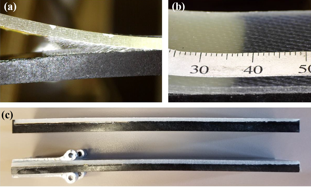
(a) ADCB specimen under load. The laminated (top) beam and overmolded beam (bottom) are actively debonding with fiber bridging present at the crack tip. (b) Crack measurements were made by comparing the delamination front (stark beige-black transition) to a ruler bonded on the specimen, which was recorded during each test via a traveling optical microscope. In this case, crack measurements were made from above the specimen, exploiting the translucent TenCate® laminate material. (c) Example of residual stress-induced curvature on ADCB specimens of different thickness.
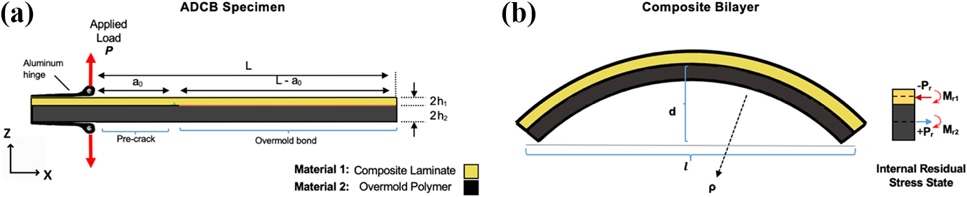
(a) Schematic representation of ADCB specimen under mechanical loading conditions, nomenclature, and sign conventions. Material 1 corresponds to TenCate Cetex® laminates, and material 2 corresponds to overmolded Lexan™ polymer material. (b) and (c) Resolved bending moments and axial forces on ADCB specimen from CTE mismatch-induced residual stress. The chord length l was measured from end-to-end, and the rise height d was measured to the arc length created by the specimen.
Mixed mode fracture is often characterized in terms of a phase angle between mode I and mode II contributions. The mode mixity phase angle, ψ, is defined as,
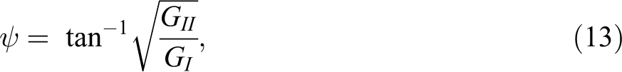
which is useful for representing the range of pure and mixed mode fracture conditions, often referred to as the fracture envelope. Since there is a stiffness mismatch between adherend materials in this work, there may be an asymmetry in the fracture envelope due to frictional and perhaps plasticity-related effects at the crack tip, which have been noted by Liechti and Chai. 28 Following their convention, a positive (+) sign on the mode mixity phase angle was assigned if the shear displacements at the crack tip produced an opening shear mode on the softer, overmolded Lexan resin material and a negative (−) sign if the shear displacements produced a closing shear mode on the softer material.
In the simplified case of purely mechanical loading (Figure 2(b)), we take the internal forces at the neutral axis of the top beam to be N1 = 0, Q1 = P, and M1 = P·a and in the bottom beam section to be N2 = 0, Q2 = −P, and M2 = −P·a, where Ni, Qi, and Mi are axial forces, transverse forces, and moments, respectively, and P is the applied load and a is the instantaneous crack length (Figure 1). Using the EBT model, the strain energy release rate components can be written in terms of globally applied loads, specimen geometry, and material properties as:
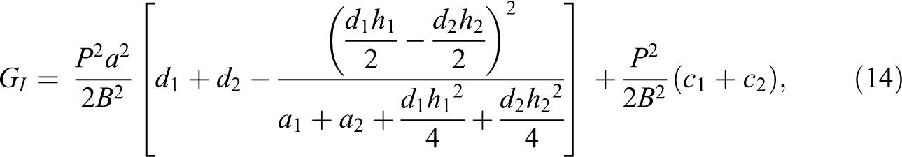
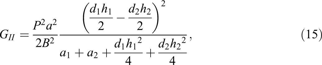
which are a special case of equations (11) and (12), respectively.
Residual curvature was measured on several specimens and interpreted using the classical analysis of bimetal thermostats, for which the ADCB specimen is a reasonable approximation (Figure 1(c) and 2(c)). An idealized isotropic bimaterial specimen subject to uniform heating or cooling will deflect if the coefficient of thermal expansion of the materials is not identical. In the case of free bending of the bimaterial strip, all forces acting over the cross section of the strip must be in equilibrium. The bending moments Mr1 and Mr2 for each beam produced by bending-extension coupling due to CTE mismatch are,
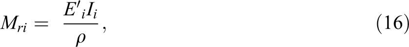
where
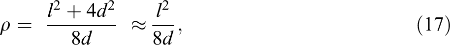
where the approximate form is valid when d is much less than l. Finally, the axial forces P1 and P2 are equal in magnitude and opposite in sign and can be related to the bending moments by,

where Pr is the magnitude of the axial forces.
The TenCate material is more accurately modeled as an orthotropic laminate, and so, the residual stress approximation can be made using CLT. In the case of a balanced, symmetric laminate,
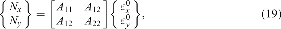
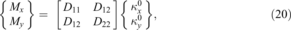
where Nx,
Results and discussion
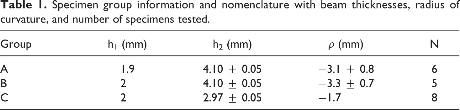
ADCB specimens were fabricated with varied laminate and overmold thicknesses, and a radius of curvature from CTE mismatch-induced residual stress was measured from a few representative specimens from each combination, with the exception of group C from which only one specimen was measured. Specimen group nomenclature, beam thicknesses, and measured radius of curvature are provided in Table 1. Specimen groups A and B were tested in an as-molded condition (i.e. unmodified). Group C specimens, originally from group B, were modified by mechanical reduction of the overmold layer thickness.
Specimen group information and nomenclature with beam thicknesses, radius of curvature, and number of specimens tested.
Fracture energy experiments were performed, where crack length, load, and crosshead displacement data were monitored and recorded for each trial. Both CBT and the ECM have been used extensively to relate the aforementioned experimental variables to fracture energy,27,34,35 which are preferred methods over SBT, at least in part because both methods use the measured specimen compliance. The equation for CBT is:
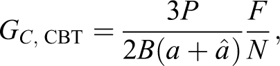
where P is the measured load, δ is the crosshead displacement, B is the bond width, a is the measured crack length,
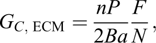
where n is a fitted value determined by the slope of a linear fit on the experimental data in the form of the logarithm of the compliance divided by the end block correction versus the logarithm of the crack length.
Experimental fracture energies computed by CBT and ECM were in excellent agreement with each other (within approximately 1%) for each trial in all groups. Critical fracture energy values as a function of crack length as computed by CBT are shown inFigure 3. Compliance and Berry’s fits were highly linear, with R2 values falling in the range of 0.989–0.999 for each specimen tested. Fracture energy as a function of crack length was approximately constant for each specimen, but within groups, fracture energies varied by as much as 15%.
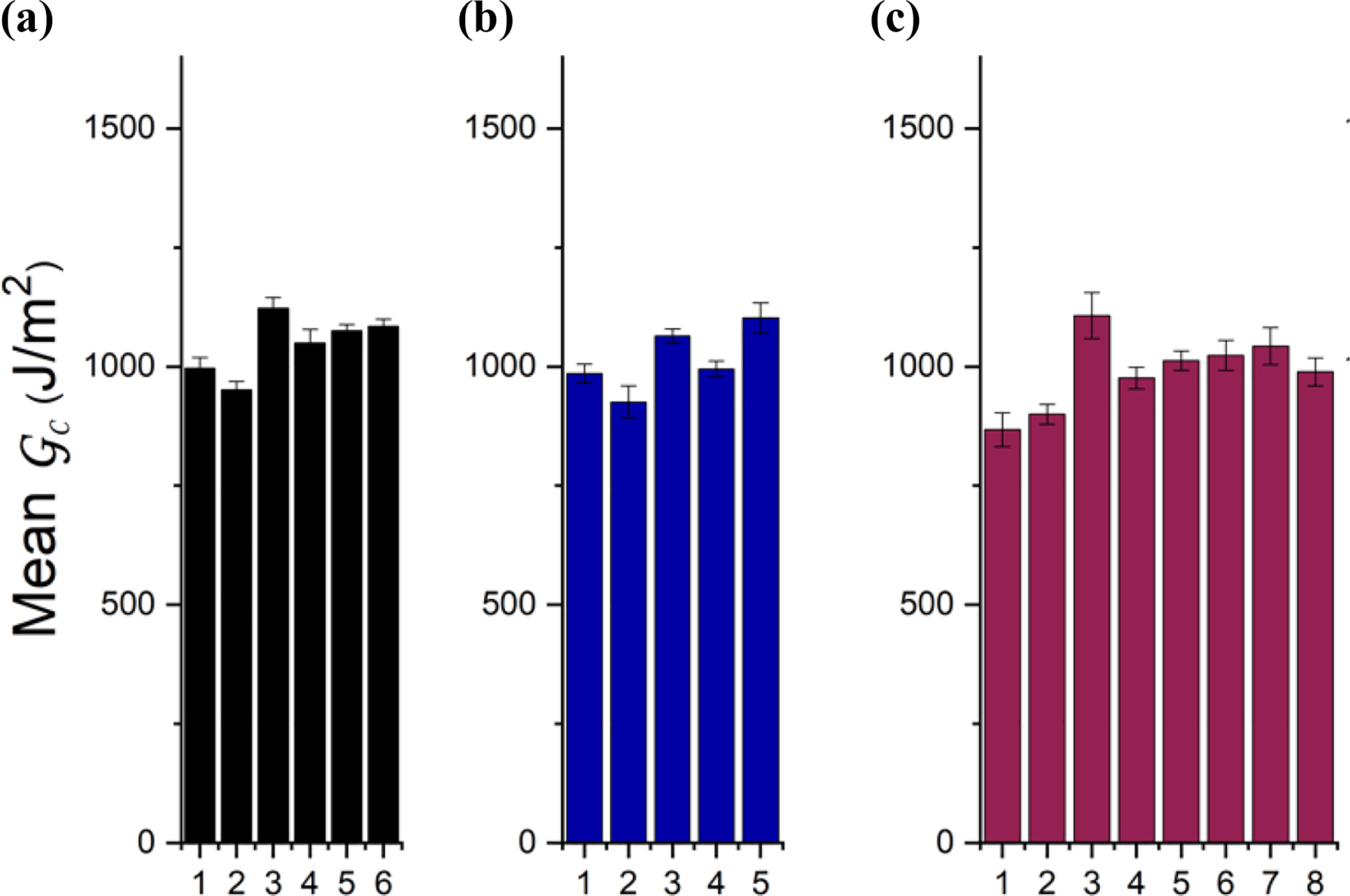
Experimentally measured mean Gc for each specimen group by the experimental compliance method. Mean Gc values were lowest for the C group, although not statistically significant. Error bars denote a 95% confidence interval on the mean of each specimen.
For comparison, fracture energy values were averaged over the crack length range of 45–75 mm from each trial and reported as a mean value (Figure 3). Some specimens featured a slightly downward trend in fracture energy with increasing crack length (Figure 4). Although time-dependent materials can exhibit such a trend, 36 the decreasing fracture energy observed here is more likely due to incomplete wetting between the polymer overmold and laminate surface. Visual inspection of the fracture surface revealed some nonbonded smooth regions adjacent to rough fracture surface, which were more prevalent on the end of the specimen that was opposite the gated inlet of the mold, suggesting incomplete bonding during manufacturing. Since these localized nonbonded regions were primarily located at the far end of specimens, the decrease in fracture energy is likely attributed to a small reduction in bond area with increasing crack length. These manufacturing-related heterogeneities were not severely detrimental to bond performance and can likely be avoided with improved laminate surface preparation and/or elevated mold preheating temperatures.
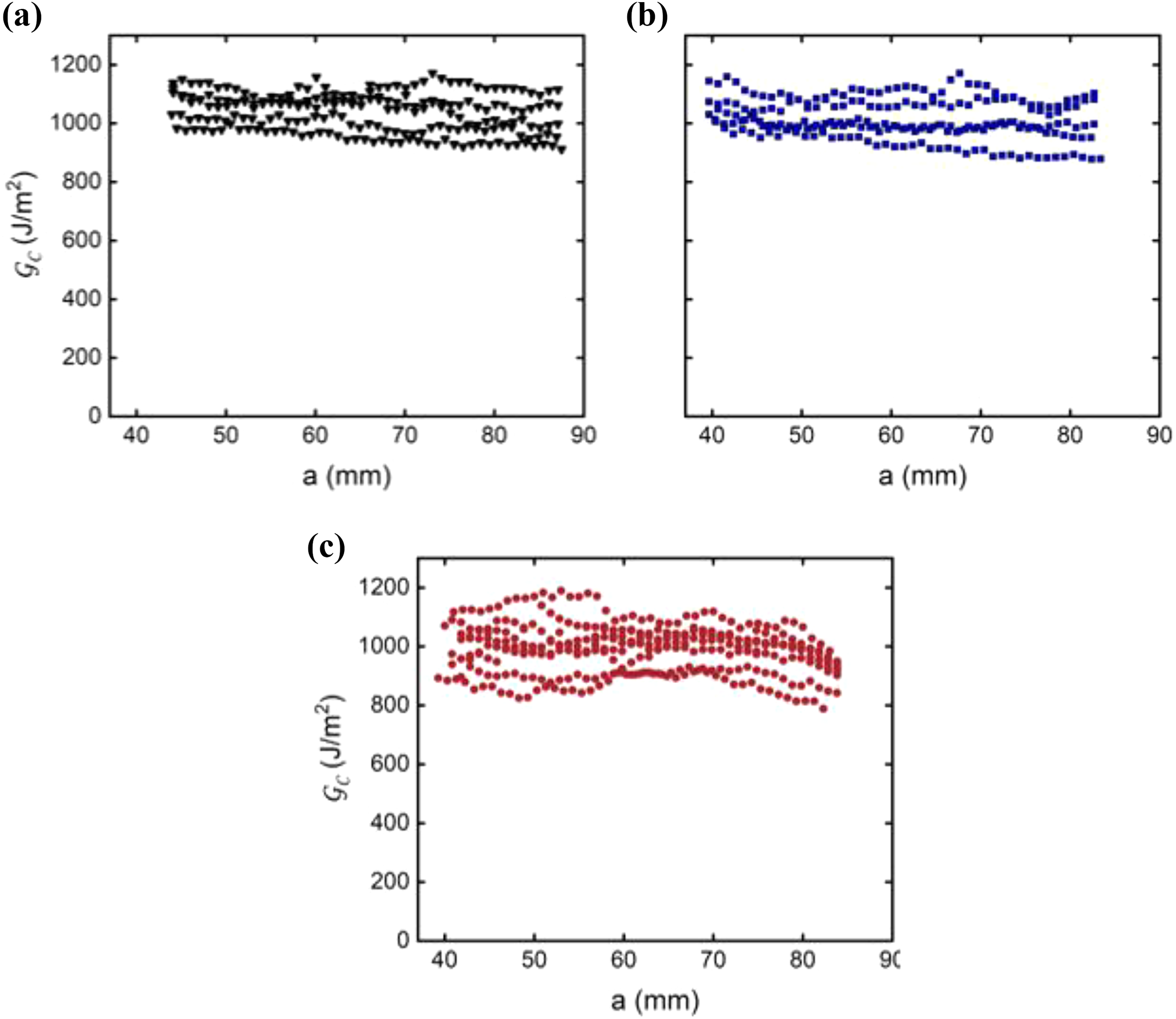
Experimental data from ADCB tests. Gc versus a for specimens in (a) group A, (b) group B, and (c) group C by the corrected beam theory method. Average values between groups are similar, around 1 kJ/m2.
In the case of purely mechanical loading (i.e., ignoring residual stress), the fracture mode mixity of the ADCB specimen was computed based on equations (13) to (16). Residual stress effects were not considered a priori, and the external loading was assumed to be the dominant factor in the fracture mode analysis, so the nominal mechanical mode mixity angle is denoted by
Mean fracture energy and mode mixity for each group.
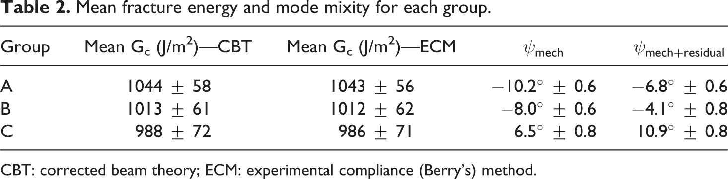
CBT: corrected beam theory; ECM: experimental compliance (Berry’s) method.
Under these processing parameters, for this material system, it can be seen that residual stress plays a relatively small role in the fracture mode mixity, producing a small opening shear (+) effect on the mode mixity angle. The shift in mode mixity angle from residual stress was 3.2°, 4.1°, and 4.4° for groups A, B, and C, respectively. It was assumed that residual stress was approximately constant between specimens in each group; however, the measured radii of curvature did not follow a consistent trend. Specifically, the specimens from groups A and B were nominally molded under the same conditions and were of similar dimensions, but the specimens measured from group A had much less apparent curvature and therefore less residual stress. This is attributed to a small systematic measurement inaccuracy related to image perspective.
The range of mode mixities explored by the ADCB specimens was intentionally narrow, intended to probe near mode I fracture conditions, which leaves conditions with appreciable amounts of in-plane shear (mode II) essentially unexplored. Previous experimental investigations have highlighted the importance of mixed mode characterization when conservative fracture energy values are sought. 30 To probe these conditions, several ADCB specimens were modified to conform to a different test geometry, the single leg bending (SLB) specimen. The SLB specimen is loaded in a three-point bending configuration, which creates a more significant mode II fracture energy component than the ADCB geometry. Two SLB specimens were tested, one with an overall mode mixity angle of approximately +29° (called SLB1) and another with a mode mixity angle of approximately −63° (SLB2). Mode mixities were computed by the generalized loading case of the EBT model (equations (11) and (12)) and include residual stress. Fracture tests on SLB1 resulted in a mean Gc of 1231 ± 54 J/m2, and SLB2 had a mean Gc of 2769 ± 188 J/m2. Details on SLB specimens and testing are provided in the Supplemental Information.
In Figure 5, mean measured fracture energy versus overall mode mixity angle is shown for all ADCB and SLB specimens, along with a second-order polynomial fit for the fracture envelope, which had an adjusted R2 value of 0.97 and a y-intercept (nominally pure mode I value) of 993 ± 16 J/m2 on a 95% confidence interval. As expected, the ADCB specimens are clustered around the minimum values of the fitted fracture envelope near mode I conditions. The results of this study suggest that this material system is most susceptible to crack propagation under fracture mode conditions in the range of approximately ±20°. SLB specimens provide some evidence that increasing the mode II fracture energy component increases the critical fracture energy, which has been reported in a number of other composite systems.37,38 The fitted curve also suggests some asymmetry in the fracture envelope with a bias toward the opening fracture mode; however, the number of trials under these conditions was limited. Although the effects of residual stress were small under the manufacturing conditions tested for this system, the approach described in this work may be useful in exploring the effects of other processing parameters and postprocessing or new material systems in general.
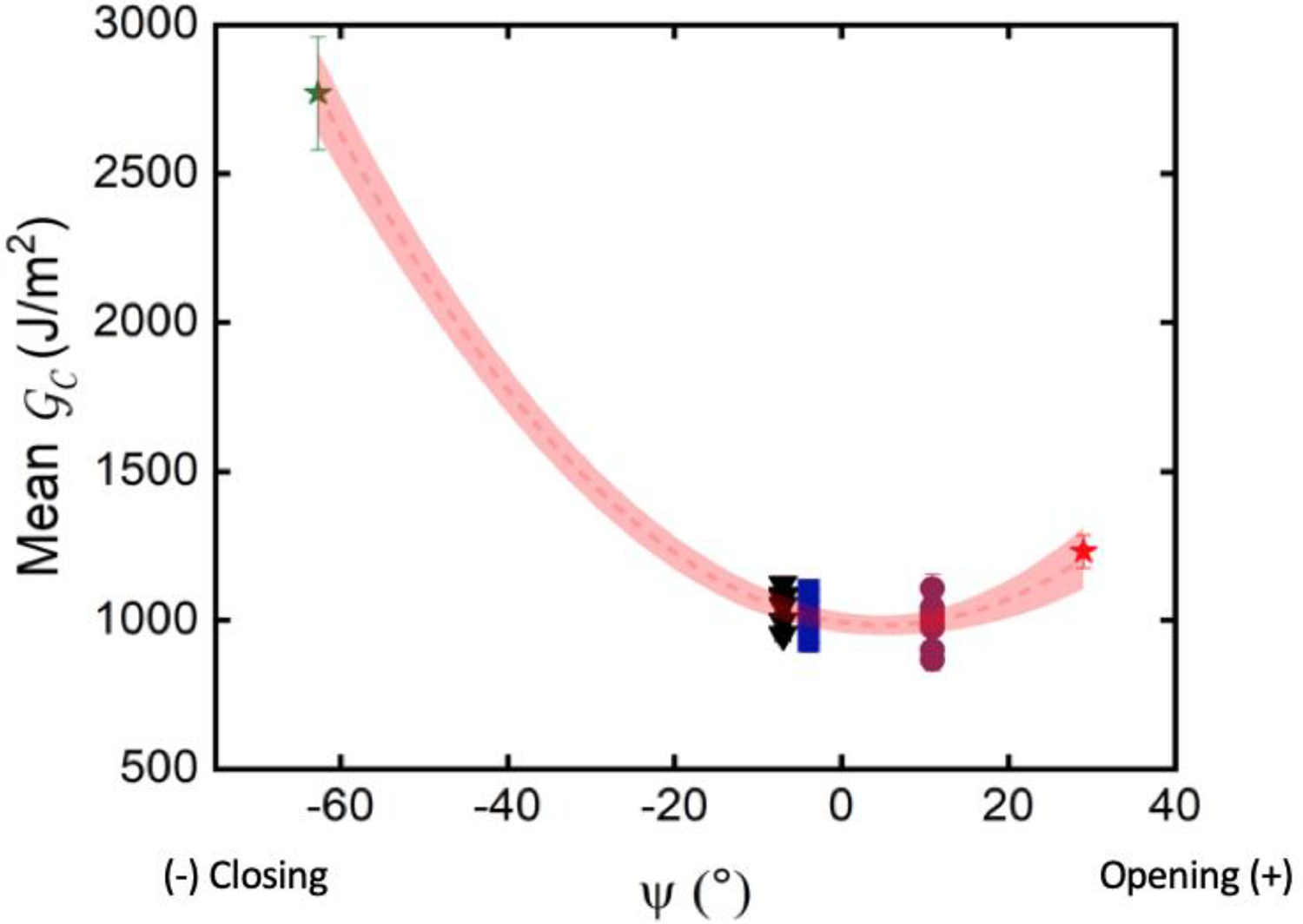
Fracture envelope Gc(ψ) with experimentally measured Gc values and overall mode mixity values. A quadratic fit was applied to the data set, with ay-intercept (mode I) value of 993 J/m2. The fitted curve has an adjusted R2 value of 0.97 and is approximately centered at 0°, which nominally agrees with the literature on other material systems.
During testing, fiber bridging was observed behind the crack tip (Figure 6). Ex-situ optical microscopy of the overmold side of the fracture surface revealed substantial fiber transfer with a pattern matching that of the warp fibers in the laminate (Figure 6). In the fracture process of many fibrous systems, fiber bridging has a strong effect on fracture energy in the form of a rising resistance curve (R-curve) with increasing crack length.26,39–41 However, the phenomenon was not observed in this material system. A possible explanation for the lack of R-curve behavior is that the over–under interaction of the glass fiber warp and weft prevented fibers from bridging over spans longer than a few millimeters, instead short fiber bridges were severed at each weave crossover intersection.
(a) Fiber bridging at and behind the crack tip on speckled ADCB specimen for digital image analysis. Broken fibers can be seen in the wake of crack advance, likely providing some shielding effect in the immediate area behind the crack tip but severed a short distance away by the weave geometry. (b) Fracture surface on nominal laminate and overmold sides of ADCB specimen. (top) The TenCate laminate weave can be seen on the left, along with a complimentary pattern of significant fiber transfer (white) on the (black) overmolded Lexan side of a single ADCB specimen. It is evident from these images that the overmold material forms a strong bond with the surface layer of the laminate, which is pulled apart during fracture.
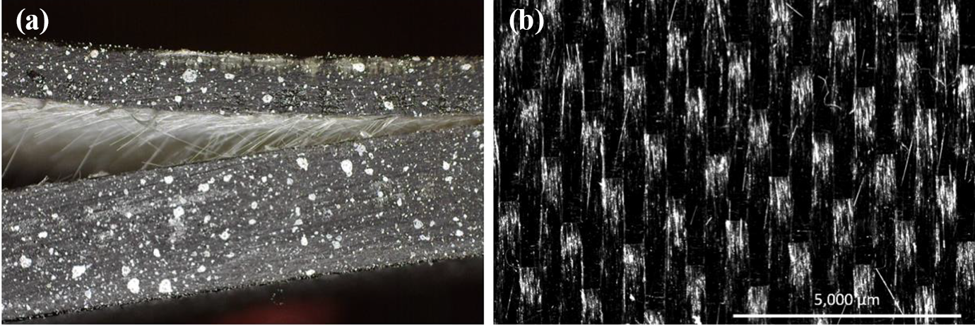
SEM images of the fracture surfaces of both TENCATE composite and overmolded Lexan can be seen in Figure 7, taken in the vicinity of the precracked region and first few millimeters of crack propagation. Supporting experimental observations of fiber bridging, images of the woven composite surface (Figure 7(b)) reveal bare fibers, some of which have been severed and pulled out of the ordered weave. Close inspection of the crack initiation site reveals a superficial layer of fractured polymer spanning only a few hundred microns, depending on initiation location. Higher magnification of the initiation site on the woven composite fracture surface in Figure 7(c) reveals more detail. The smooth region at the bottom of the image is representative of the thermoplastic polycarbonate (PC) surface finish on the composite laminate. During specimen manufacturing, a single layer of Kapton tape was adjoined to this surface to prevent bonding between the laminate and overmold structure (precrack formation). Immediately adjacent to the smooth surface is the crack initiation site, nominally the overmold interface. Apparently, the crack initiates at the desired interface, propagates only a short distance (approximately 200 µm at that particular location), and is then diverted to the nearby interface between the polycarbonate surface layer on the composite laminate and the top of the glass fiber weave below.
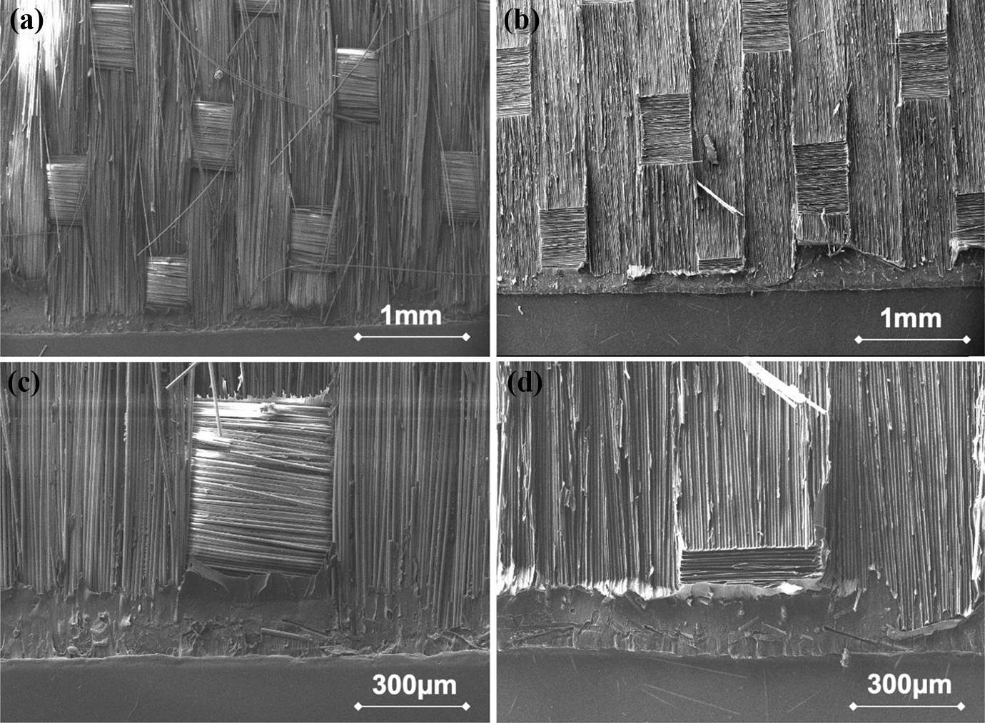
(a) and (b) The TenCate laminate weave can be seen on the left, along with a complimentary pattern of significant fiber transfer (white) on the (black) overmolded Lexan side of a single ADCB specimen. (c) and (d) Increased magnification of local weave pattern along with complementary fiber transfer. Several fibers can be seen broken and frayed on the laminate side and transferred fiber patches on the overmold side. It is evident from these images that the overmold material forms a strong bond with the surface layer of the laminate, which is pulled apart during fracture.
Complementary images of the other fracture surface, nominally the overmolded Lexan side, support previous hypotheses on the nature of the locus of failure. In Figure 7(b), a smooth surface can be seen at the bottom of the image, which is simply Lexan material that was in contact with the Kapton tape in the precrack region. Crack initiation occurs at the overmold interface nearby but quickly switches to a new interface, which is patterned with a negative imprint of the glass fiber weave. In Figure 7(a), a close-up can be seen of the crack initiation site at the overmold interface and transition to the laminate surface layer. Distinct grooved impressions characterize this surface, suggesting that the majority of fibers detached from the failure surface in a peeling motion during specimen debonding. However, fiber fracture and transfer can be seen in select regions, perhaps preferentially at the border between adjacent weave strands and crossover locations. Despite crack initiation at the desired overmold interface, the locus of failure of all specimens appeared to be identical, including the SLB specimens which had a more significant mode II fracture energy component. Evidently, the manufacturing procedure consistently produced a bond of higher interfacial toughness than the internal laminate interface at which failure consistently occurred, indicating that the overmold interface is apparently the tougher of the two. So, in this particular case, it appears that the fracture energy data are more reflective of the laminate toughness than the overmold–laminate interface. However, this testing approach may be useful for characterizing other overmolded systems with interfacial bonds that are less tough than nearby laminate interfaces and/or be used to evaluate various processing parameters. Some additional images of the fracture surface and operation details of the electron microscopy may be found in the Supplemental Information, along with an implementation of a cohesive zone model to simulate ADCB specimens using finite element analysis.
Previously, it was mentioned that the orientation of TenCate Cetex laminates was such that the warp direction of the outermost layers was aligned with the crack growth direction. However, limited testing was performed (N = 2) on ADCB specimens inadvertently prepared with laminates rotated by 90°, so that the crack propagation direction was aligned with the weft direction instead. Surprisingly, experiments on the overmolded specimens with rotated laminate orientations revealed fracture energies of greater magnitude, despite nearly identical nominal mechanical properties. A specimen with a mode mixity angle of −18° had a mean Gc of 1975 ± 126 J/m2, almost double the mean fracture energy of comparable specimens from the standard laminate orientation. Another specimen with nominal mode mixity angle of approximately −25° had a mean Gc of 2210 ± 281 J/m2, nearly 50% higher than that of the specimens with standard orientation. Although limited in number, these results indicate a pronounced orientation effect in fracture energy, presumably caused by changes in fiber orientation close to the overmold interface. Some literature indicates that there can be orientation dependencies on crack propagation between woven lamina; 42 however, a factor of two difference is not expected, especially when other literature suggests that for balanced symmetric woven lamiantes, crack propagation along the warp and weft direction should be similar. 43 We note that failure here is similar to interlaminar failure, not translaminar failure, which typically show orientation dependencies (e.g. Liu and Hughes 44 ). If further tests confirm these observations, the stark difference should serve as a caution for preparing specimens as well as for the design process. Several additional details are provided in the Supplemental Information. Future work may be devoted to characterizing the fracture energies associated with other laminate orientations and explaining the orientation-dependent toughening mechanism.
Conclusion
A general experimental approach was presented for identifying mode I fracture conditions in hybrid overmold composite specimens utilizing the ADCB geometry. The EBT model provides a convenient, closed form solution for mode mixity in hybrid specimens and is easily integrated with an estimation of residual stress, computed directly from specimen curvature. Experiments on the Lexan/TenCate material system resulted in near-mode I fracture energies of about 1 kJ/m2 by both ECM and CBT analyses. Mode mixity effects on the magnitude of fracture energy appear to be subtle near mode I conditions; however, SLB specimens provide some evidence for elevated fracture energies with greater mode II fracture energy component. Residual stress was included in the mode mixity analysis and was found to have a small, opening shear effect on the fracture mode mixity. Although rising R-curve behavior was not observed, fiber bridging during fracture and the visual appearance of fracture surfaces indicates that the locus of failure was in the surface layer of the TenCate Cetex laminate rather than at the nearby overmold interface. Presumably, molecular interdiffusion during molding is responsible for the more resilient overmold interface. Future work may be directed toward understanding the mechanism behind weave orientation dependence on specimen fracture energy and driving interfacial failure toward the nominal overmold interface through variation of processing parameters.
Supplemental material
Supplement - Fracture characterization of overmold composite adhesion
Supplement for Fracture characterization of overmold composite adhesion by W Douglas Hartley, John McCann, Scott Davis, Tom Hocker, Somasekhar Bobba, Nikhil Verghese, Devendra Bajaj, Hang Z Yu and David A Dillard in Journal of Thermoplastic Composite Materials
Footnotes
Authors’ note
Figures and tables are provided for general information and are not for the purpose of warranty or specification. All resins and mixtures discussed herein should be thoroughly tested in actual parts under end use conditions before incorporation into any device. SABIC and brands marked with ™ are trademarks of SABIC or its subsidiaries or affiliates. Any brands, products, or services of other companies referenced in this document are the trademarks, service marks, and/or trade names of their respective holders.
Acknowledgements
The authors would like to acknowledge the LORD Corporation for supplying the adhesives used to attach end blocks in this study. We also acknowledge the Macromolecules Innovation Institute for travel support and for fostering interdisciplinary research in adhesion science.
Funding
The author(s) disclosed receipt of the following financial support for the research, authorship, and/or publication of this article: The authors acknowledge that the financial support for this work was provided by SABIC.
Supplemental material
Supplemental material for this article is available online.
References
Supplementary Material
Please find the following supplemental material available below.
For Open Access articles published under a Creative Commons License, all supplemental material carries the same license as the article it is associated with.
For non-Open Access articles published, all supplemental material carries a non-exclusive license, and permission requests for re-use of supplemental material or any part of supplemental material shall be sent directly to the copyright owner as specified in the copyright notice associated with the article.