
Abstract
A promising strategy to decrease cycle times for manufacturing continuous-fibre–reinforced composites is processing of thermoplastic matrix systems due to their fast processability, since no cross-linking of molecular chains is required as for thermoset resin systems. Nevertheless, thermoplastic carbon fibre-reinforced plastics nowadays are predominantly manufactured with pre-impregnated sheet materials, which result in limited drapability and freedom of design. Hybrid textiles, consisting of thermoplastic and carbon fibres, can avoid these disadvantages. This class of reinforcements combines the drapability of dry textiles with thermoplastic matrices, which furthermore allow near net-shape processes. Relative shifting between the fibres and, consequently, draping is possible in a preforming step. The objective of this article is to expand our knowledge about hybrid textiles with regard to their thermal behaviour during compression moulding. Accordingly, the necessary parameters for modelling the thermal state of the dry textile and the impregnated laminate are investigated. Moreover, an in situ process analysis based on the reflection spectra of glass fibre-optical sensors, which are embedded inside the stacking, is investigated to provide information about the state of aggregation and to validate the thermal model.
Introduction/literature
In recent years, thermoplastic composites have become increasingly interesting for future aircraft applications due to their advantageous processing properties. Out-of-autoclave processability and fast cycle times are main advantages of this material class. As semi-crystalline thermoplastics are advantageous in terms of impact resistance and improved chemical resistance, they attract particular attention.
Hybrid thermoplastic- and carbon fibre-reinforced textiles can be classified into two different types based on the scale of arrangement of the two semi-finished components: reinforcement fibres and matrix fibres (Figure 1). These types are textiles from hybrid rovings, for example, commingled yarns (mix of reinforcement fibres and matrix fibres in the roving) or side-by-side arrangements (e.g. side-by-side arranged non-crimp fabrics (NCFs)). In addition to film-stacked or powder-coated preforms, which are preferably used for pre-impregnating thermoplastic laminates, textiles containing thermoplastics in the form of yarns are limited to very special applications. They usually take benefit of the improved in- and out-of-plane drapability or a load path optimized fibre orientation as for textiles being processed by tailored fibre placement 1 Framework structures for high acceleration purposes as handling robots, sports equipment as rackets for tennis or ice-hockey or frameworks for small drones or fast rotating propellers are examples for possible applications.Hybrid textiles offer opportunities to reduce raw material costs because impregnation and the final consolidation take place simultaneously in the manufacturing process (not before). Compared to fully pre-impregnated laminates, they enable a significantly higher in-plane deformation, since unimpregnated fibres allow a relative shifting against each other. 2 In contrast, however, the process of impregnating the rovings takes place during forming, which increases process times.
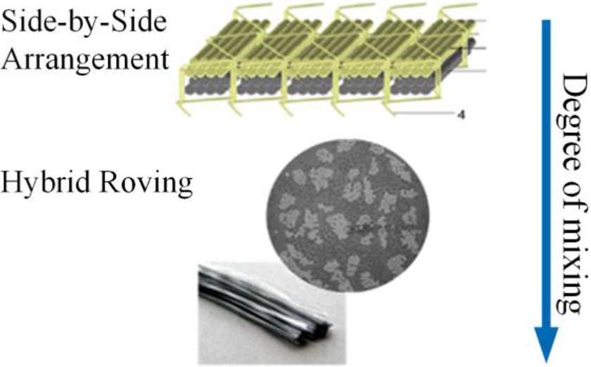
Classification of hybrid thermoplastic-carbon fibre systems.
Raw materials/yarns
Thermoplastic yarns are manufactured by a melt-spinning process. The molten thermoplastic material is pressed through a die plate perforated by small holes so that fibres can be drawn. The drawing process including heat supply by calender-rolls can influence post-crystallization and thus the further behaviour as a matrix fibre in the compression moulding process. To ensure a stable process throughout consolidation, the shrinking behaviour of the hybrid yarns must be considered, since thermal shrinkage can lead to a displacement of the hybrid preform within the tooling cavity during heating above the glass transition temperature
Commingling/side-by-side
Due to high viscosities of thermoplastic polymers as polyether ether ketone (PEEK), which are about three decades above those for thermoset resin systems, it is a key requirement for impregnation to minimize flow distances. Two variants of hybridization are particularly relevant for hybrid textiles. One promising strategy is commingling of thermoplastic and reinforcement fibres by spreading both rovings and mixing them with an air jet. 5 According to Kravaev et al., the quality of the fibre disposition in a commingling yarn is assessed on basis of two parameters: the homogeneity of the filament distribution and the blending quality, which is defined by the degree of mixing. 6 The second strategy for hybridization is to deposit thermoplastic and reinforcement fibre on top of each other for a side-by-side arrangement. In fact, the flow path length for impregnation is directly linked with the degree and homogeneity of spreading, and, therefore, the required period of time for impregnation is potentially higher than for commingling yarns. However, for the side-by-side arrangement, the carbon fibre filaments are neither damaged by an air jet nor there is an additional process step of commingling. 7
Textile manufacturing
In a subsequent step, the yarns are processed to textiles. All common textile processes are feasible as there are tailored fibre placement, 7 weaving, non-crimp fabric (NCF) manufacturing 8 or braiding, for instance.9,10 For manufacturing, an NCF with side-by-side deposition of thermoplastic and carbon fibre, both ply-wise arranged fibres can also be aligned in different orientations. 11
Thermoforming
Thermoforming of hybrid textiles comprises the steps of heating and melting the thermoplastic fibres, impregnating, cooling and solidifying the matrix, all in conjunction with applied pressure.
12
This process of consolidation can be performed in several technologies, all of which must cover the triangle of time, temperature and pressure. In particular, the high melting temperatures
Objectives of paper
To achieve the required laminate quality, a knowledge-based understanding of the consolidation process is required, which can be subdivided into the following subprocesses: heating of the dry preform, impregnation and ply compaction, so as cooling including solidification. To gain knowledge about the temperature and the aggregate state of the thermoplastic material, this article focusses on methods and experiments for determining the local temperature inside a preform during consolidation in a novel compression moulding process. The results shall help to improve especially those thermoforming processes, which enable short times for heating and cooling. The application of compression forces for impregnation requires a fully molten state of the thermoplastic material throughout the whole preform thickness. Ejection, on the other hand, requires the composite temperature to be below the glass transition temperature. Therefore, a model shall be developed and validated to give a precise prediction of the thermal state.
Experimental setup
Material
The subsequent experiments cover the thermal process properties of a hybrid NCF. It contains carbon and PEEK fibres in a ply-wise arrangement. A ply-wise arrangement of thermoplastic and carbon fibres was chosen instead of premixed hybrid rovings. In place of minimized impregnation distances, the flow front needs to penetrate the half ply thickness. Hybrid rovings, however, are normally mixed by means of air jets. This process tends to partially break the carbon fibres, which is the reason that unmixed carbon fibres are chosen here. 5
As reinforcement fibre, a 12-k carbon fibre with thermoplastic sizing is used (Teijin Limited, Teijin HTS45 12 k P12). A self-spun matrix fibre from Victrex plc, VICTREX PEEK 151G, which contains 100 filaments and at a density of 500 tex, is processed as matrix fibre. The textile is produced in a [60CF/90PEEK]-setup, which previously delivered good results for in-plane draping in preliminary tests. 11
At an aerial weight of 370 g/m2, the combination of both fibre types in the NCF yields a global fibre volume content of 55%. Besides the matrix roving, the sewing yarn is made of PEEK as well. The centre and the left-hand side of Figure 2 display the top and bottom view of the hybrid textile. The right-hand side shows a cross-section of a preform containing several plies, which are embedded in epoxy resin and where the PEEK fibres are subsequently dyed red using an image processing program.
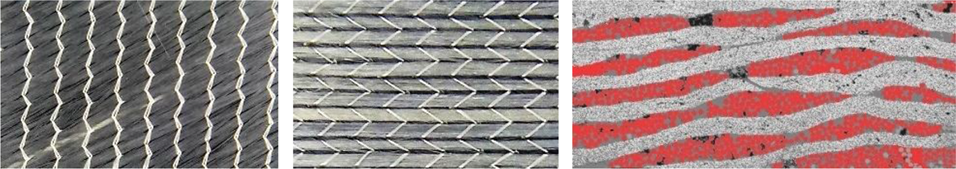
Top view and bottom view on hybrid-NCF [60CF/90PEEK] (left); cross-section of hybrid textiles in a preform stacking (thermoplastic fibres dyed in red) (right).
Process
The novel developed isoforming compression moulding process is schematically shown in Figure 3, including a process diagram. A characteristic property of the isoforming process is the cavity, which does not include temperature management but only has a shape-giving function. It was developed to gain fast heat supply into the cavity respective a fast heat flux out of it. The cavity itself contains the negative tooling, the preform inside and a pressure board, which creates the die-edge together with the negative tooling.
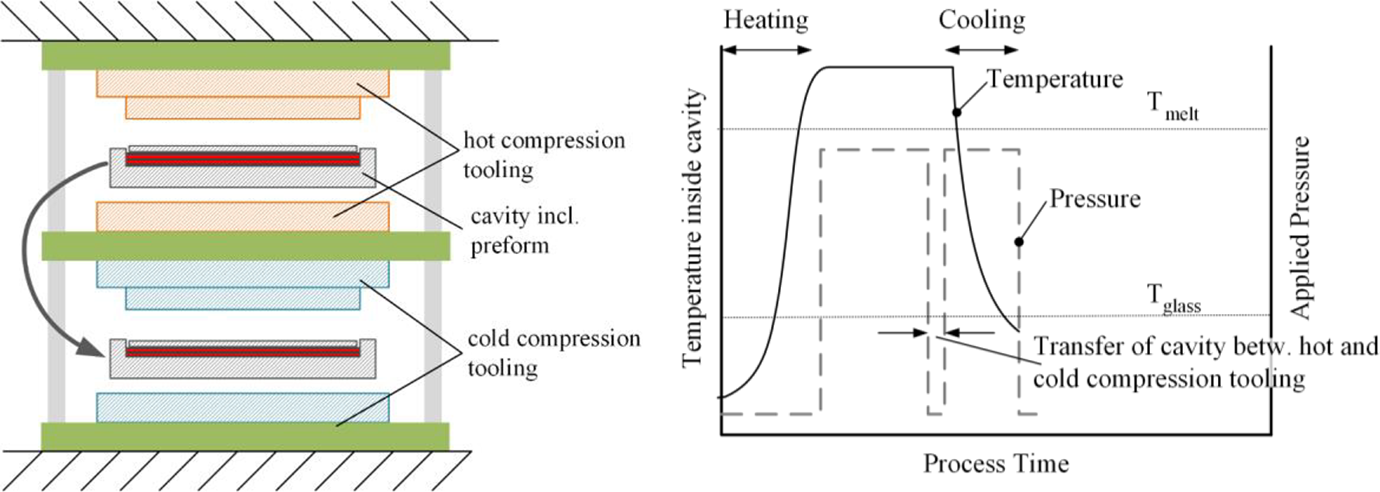
Setup of isoforming process with hot compression tooling (orange), cold compression tooling (blue) and the manually transferrable and shape giving cavity inside a press system (left); schematic of process parameters (right).
Heating and cooling of the isoforming process rely on heat conduction between the cavity and two vertically stacked isothermal compression tooling. For the phase of heating and impregnation, the cavity is placed and compressed between the two hot tooling components at the top of the system. In order to apply pressure, the tooling system is placed inside a vertical press, which is able to close and to open the setup.
The compression tooling are heated by electric cartridges to gain the process temperature, for example, 400°C for PEEK. Provoked by direct contact to the compression tooling, the temperature inside the cavity increases as soon as the press closes. On the other hand, temperatures inside the compression tooling do not drop significantly due to their considerably higher total heat capacity compared to the cavity. After impregnation, the mould opens and the cavity is transferred manually or by automation in between the cold compression tooling components. During this transfer, no pressure is applied onto the preform, which can provoke expansion of entrapped voids. However, if voids expand, they are directly compressed when pressure is applied again by the cold compression tooling. The direct contact between cavity and tooling induces a heat flux into the cold tooling, which enables solidification of the composite. Similar process developments already have been conducted by the Netherlands Aerospace Centre for two-dimensional profile geometries from chopped fibres. 17
Heat transfer
To investigate the thermal characteristic of the preform during heating, respective to the impregnated laminate during the cooling step, a thermal model is developed below. First, the thermal diffusivity of the hybrid textile is experimentally investigated to be able to model the heat transfer into the unimpregnated preform. Afterwards, necessary material parameters of PEEK are experimentally determined to model the transient temperature distribution (heat capacity, density and thermal conductivity).
Heat transfer in hybrid textiles
In the dry or unimpregnated state, the presence of the thermoplastic fibres can have a negative effect on heat transfer within hybrid textiles. Thermoplastic materials generally have low thermal conductivity compared to carbon fibre, which makes it interesting to quantify their effect in hybrid textiles. To analyse this, experimentally determined values concerning the thermal diffusivity of hybrid textiles are examined in their dry state on macroscale.
To investigate the thermal diffusivity through the textile, a clamp holder for textiles is used within a Netzsch LFA 457 laser-flash analysis (LFA). For determination of the thermal diffusivity by an LFA, the sample inside a chamber is heated to the required temperature and a heat impulse by a laser beam is applied to one side of the sample. The heat is absorbed by the sample, which results in increasing temperature on the opposite side after short time. Time and temperature are measured by means of an infrared sensor. Subsequently, the data can be used to calculate the heat capacity, thermal diffusivity and conductivity. 18 In contrast to solids from neat polymers the thermal conductivity of textiles depend on further parameters, in particular air between the filaments. These parameters are adjustable by applied pressure, so that compressed textiles promise increased values for thermal conductivity. To capture this, a sample holder for textiles allows adjusting the applied pressure to 0.5 MPa in the experiments. The samples include five plies of the hybrid NCF described above, containing one carbon- and one PEEK-ply each with a diameter of 10 mm.
The obtained data from two analysed samples, illustrated in Figure 4, provide values between 0.1 mm2/s and 0.18 mm2/s. The fluctuating values can be explained by the inhomogeneous microstructure of the compressed textile, which presumably tends to rearrange during heating. A dependence of the diffusivity to temperature cannot be interpreted from the data. Consequently, a constant value of 0.15 mm2/s (standard deviation of 7%) for thermal diffusivity of the dry hybrid textile is considered for the subsequent thermal model. An interesting observation is that, despite the presence of thermoplastic fibres, the values are at a comparable dimension as for NCF only consisting of carbon fibres. For those classical NCF, the experimentally measured values for thermal diffusivity are between 0.1 mm2/s and 0.3 mm2/s (not illustrated here), which is also in good agreement to the obtained data from Yang et al. or Schäfer et al.
19
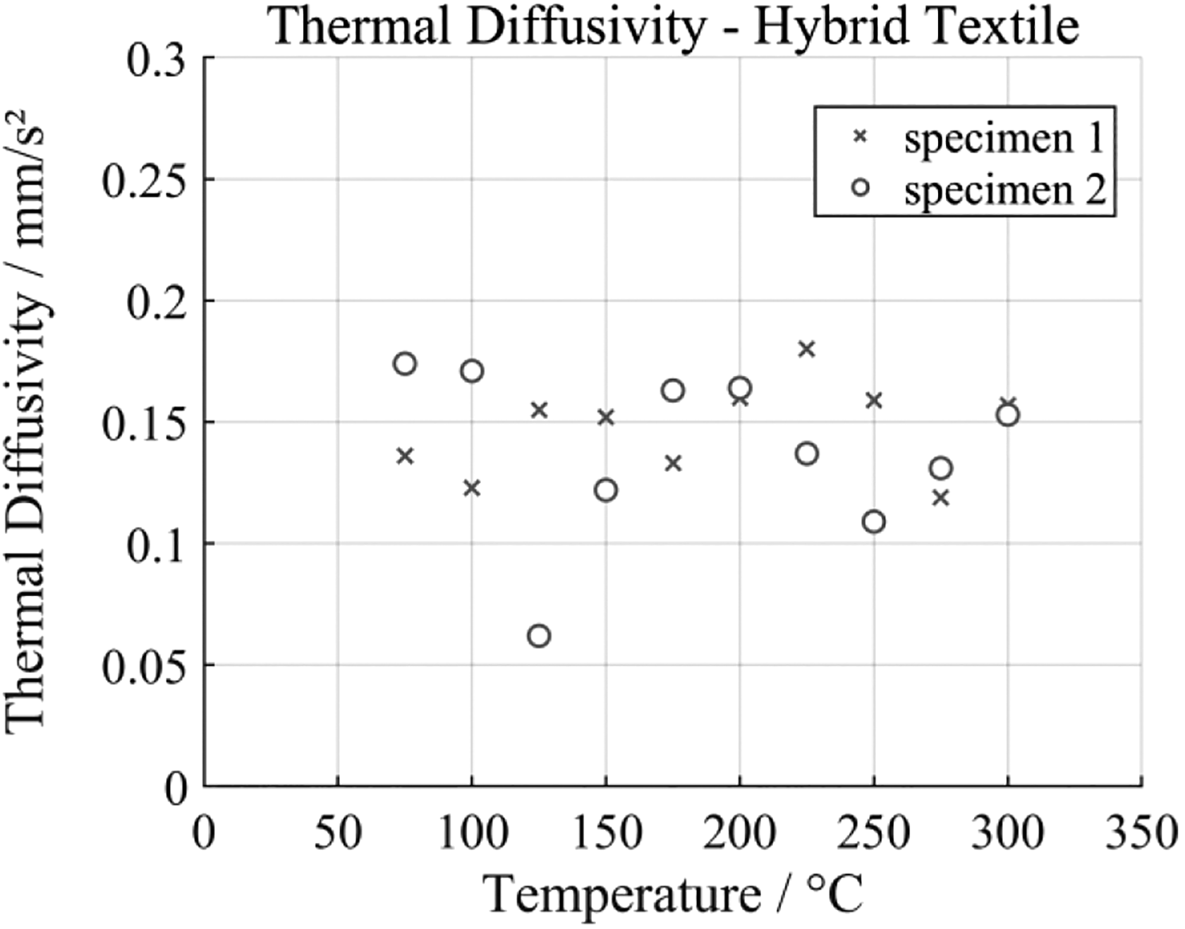
Thermal diffusivity of the hybrid NCF.
Heat transfer in an impregnated state
Heat capacity of PEEK
The specific heat capacity
There are various measuring principles applicable for determining the specific heat capacity of polymers or compounds. An adequate facility is a temperature-modulated differential scanning calorimeter (TMDSC), which performs a modulation of the temperature. TMDSC separates thermodynamic and kinetic effects and directly provides a value for the temperature-dependent specific heat capacity. 21 Kinetic effects are irreversible (crystallization and degradation) and are not affected by the modulation. Thermodynamic effects (melting and glass transition) are reversible and are considered for the determination of the heat capacity.
During analysing by TMDSC, a low-frequency sinus-wave with low-temperature amplitude is applied to the temperature program. For calculating the heat capacity, the currently modulated heat flux is divided by the modulated heating rate. A TMDSC Q 2000 by TA Instrument is used for determining the specific heat capacity of PEEK 151G. The parameters chosen for the analysis are listed in Table 1.
Parameters for TMDSC measurement.
TMDSC: temperature-modulated differential scanning calorimeter.
The results, illustrated in Figure 5, indicate an increasing heat capacity with respect to a rising temperature. As significant regions, the glass transition at temperatures around 150°C and the melting region are clearly identified. Heat capacity is directly linked with the ability of molecules to oscillate. This, in turn, is directly dependent on the density. Consequently, the specific heat capacity normally increases with temperature for semi-crystalline thermoplastic polymers. 22 At the transition from solid to a molten state, energy is required to break the crystalline fractions, which is reflected in a peak of the heat capacity. 4
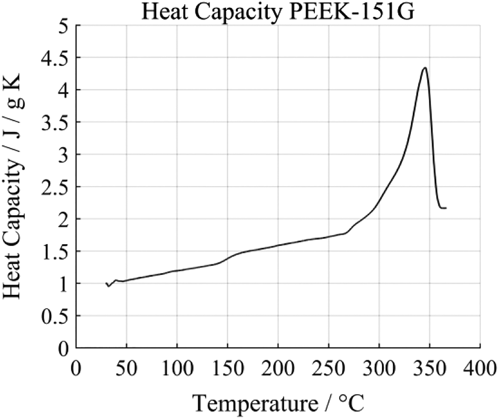
Measured temperature-dependent heat capacity of PEEK 151G.
Density of PEEK
Especially, modelling of the heat transfer requires knowledge about the density of the material used. It is assumed that the density of the polymer is not affected by the acting pressures during compression moulding. This simplification has proven to be valid by Nilsson et al. 23 To describe the specific volume, the density of the polymer is calculated using the thermal expansion data obtained for PEEK 151G, measured using a thermomechanical analysis unit (TMA) Q400 by TA Instruments. The unit consists of a heated chamber including a movable stamp, which is placed with a force of 1 mN onto the test specimen, small enough not to counteract the expansion of the specimen during heating. The specimens consist of neat PEEK 151G. For the determination of the coefficient of thermal elongation at different temperatures, the expansion of the three specimens is detected by the stamp during heating of the chamber.
The corresponding values for the temperature-dependent density
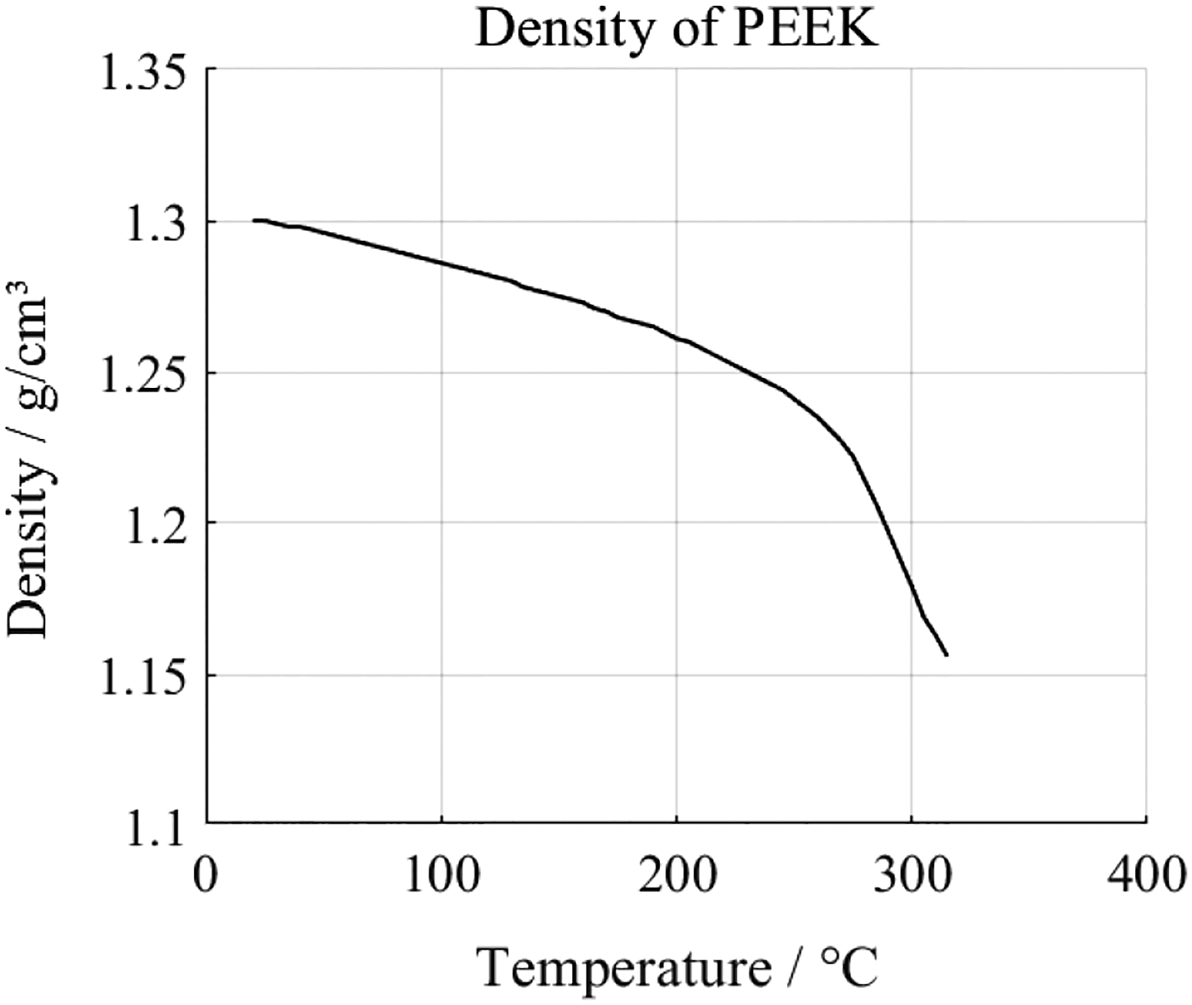
Derived temperature-dependent density of PEEK 151G.
Thermal conductivity of PEEK
Heat is conducted through the composite during the process stages of heating to process temperature and cooling after impregnation. Accordingly, the values of the thermal conductivity are of great importance to allow modelling the heat transfer.
In addition to the temperature, which is the most important influencing factor, the degree of crystallinity (DoC) and the arrangement of the crystallites also influence the thermal conductivity of semi-crystalline polymers. Previous research activities showed that the bulk thermal conductivity differs by 10% between entirely amorphous and highly crystalline PEEK (without predominant direction of the crystallites), which is the reason for not considering it here. 24 For a more detailed analysis, however, the influence of the DoC and, furthermore, the degree of orientation of the crystallites should be assessed, since it can lead to a significant direction dependence of the thermal conductivity in case of a predominant alignment (almost factor 3 between parallel and transverse direction to the crystallites). 24
For semi-crystalline polymers, especially, the phase change from solid to molten state is affected by the crystalline fractions due to different melting temperatures of crystallites. 21 Above melting temperature, the decreased density causes a decreased conductivity. On the other hand, an increasing mobility of molecules enables a higher conductivity, so both effects are counteracting.
As for the dry hybrid textiles, a Netzsch LFA 457 LFA is used to evaluate the temperature dependency of the thermal diffusivity aT. The evaluation of the thermal conductivity

To ensure a constant temperature over the entire sample thickness, a low heating rate of 0.33 K/min is selected. After each 10 K increase in temperature, data on the thermal conductivity are determined. Injection-moulded PEEK sheets with 2 mm thickness and a diameter of 25.4 mm are used as specimens. The measuring direction is in their out-of-plane direction. All relevant experimental parameters are shown in Table 2.
Parameters for measurement of thermal diffusivity.
The obtained data are shown in Figure 7. Here, a decreasing thermal diffusivity is observed with respect to a rising temperature. For temperatures above 300°C, a constant diffusivity is assumed for further modelling.
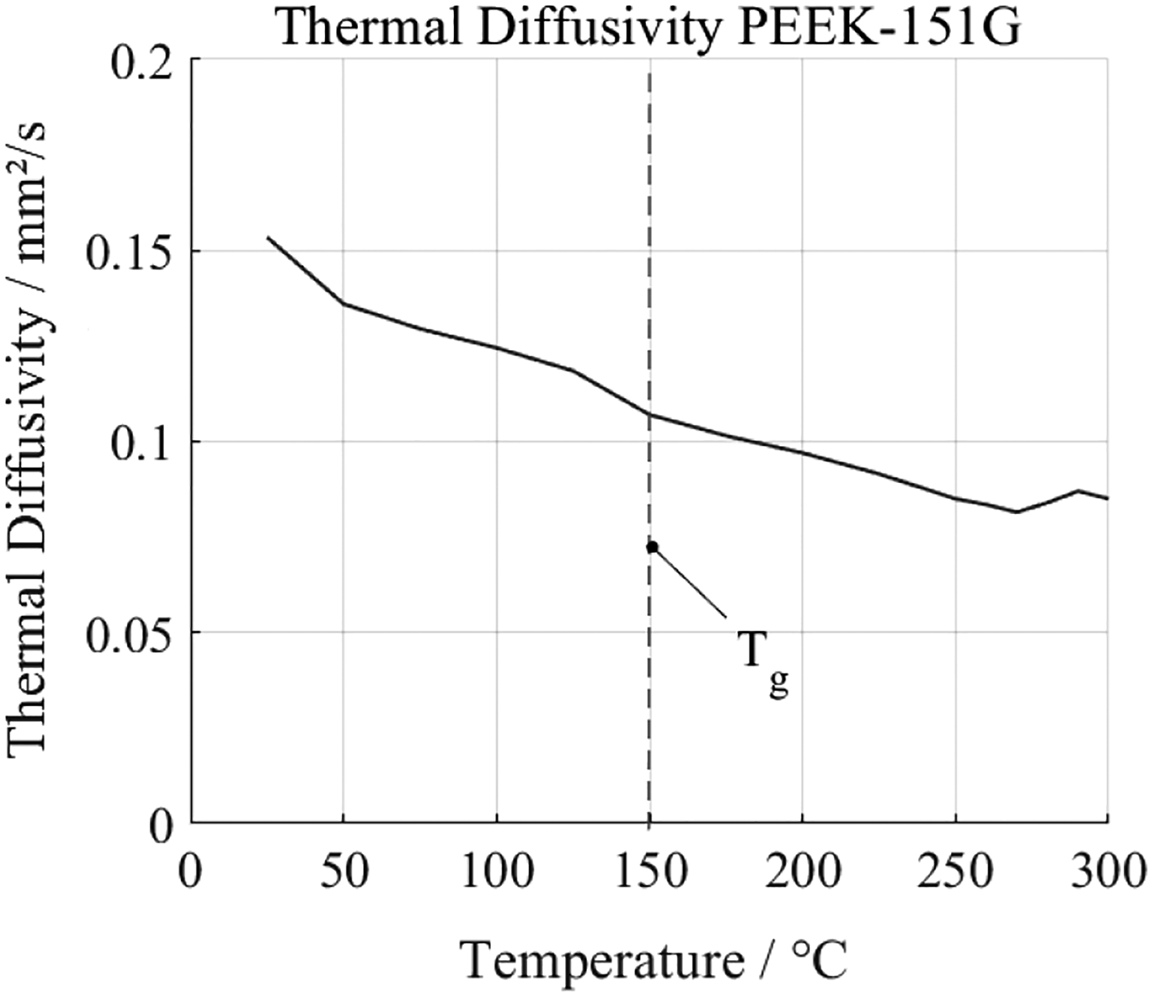
Measured temperature-dependent thermal diffusivity of PEEK 151G.
Thermal diffusivity in a consolidated laminate
To address the impregnated state of a fibre-reinforced laminate during the cooling phase, the thermal conductivity

The previously observed data for the conductivities and the density are considered here. Thermal data for carbon fibres are obtained from Ohlhorst (configuration #1) et al. 27
For determination of the thermal diffusivity of the laminate

Using the experimentally obtained and modelled values from this and the previous chapters, the diagram in Figure 8 shows the modelled thermal diffusivity for an impregnated laminate. In the following, these data are utilized as direct temperature-dependent and fibre-volume content-dependent values.
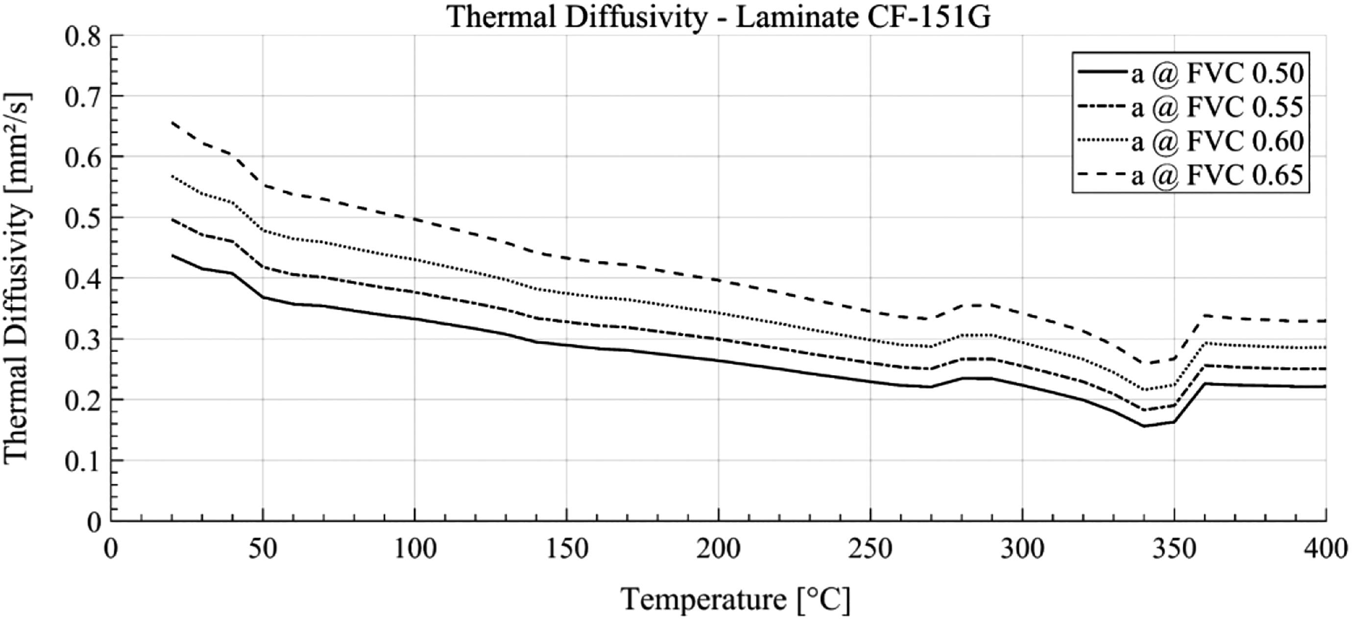
Modelled temperature-dependent thermal diffusivity of laminates.
As a conclusion, thermoplastic fibres inside hybrid yarns have little influence on the thermal conductivity of hybrid textiles. Furthermore, hybrid textiles are relatively unaffected by temperature changes. The authors assume that the applied pressure has a significant higher effect on heat transfer inside the textile. For impregnated laminates, it was shown that the fibre volume content is the key parameter to adjust the heat transfer in a laminate.
Modelling the thermal characteristic of the isoforming process
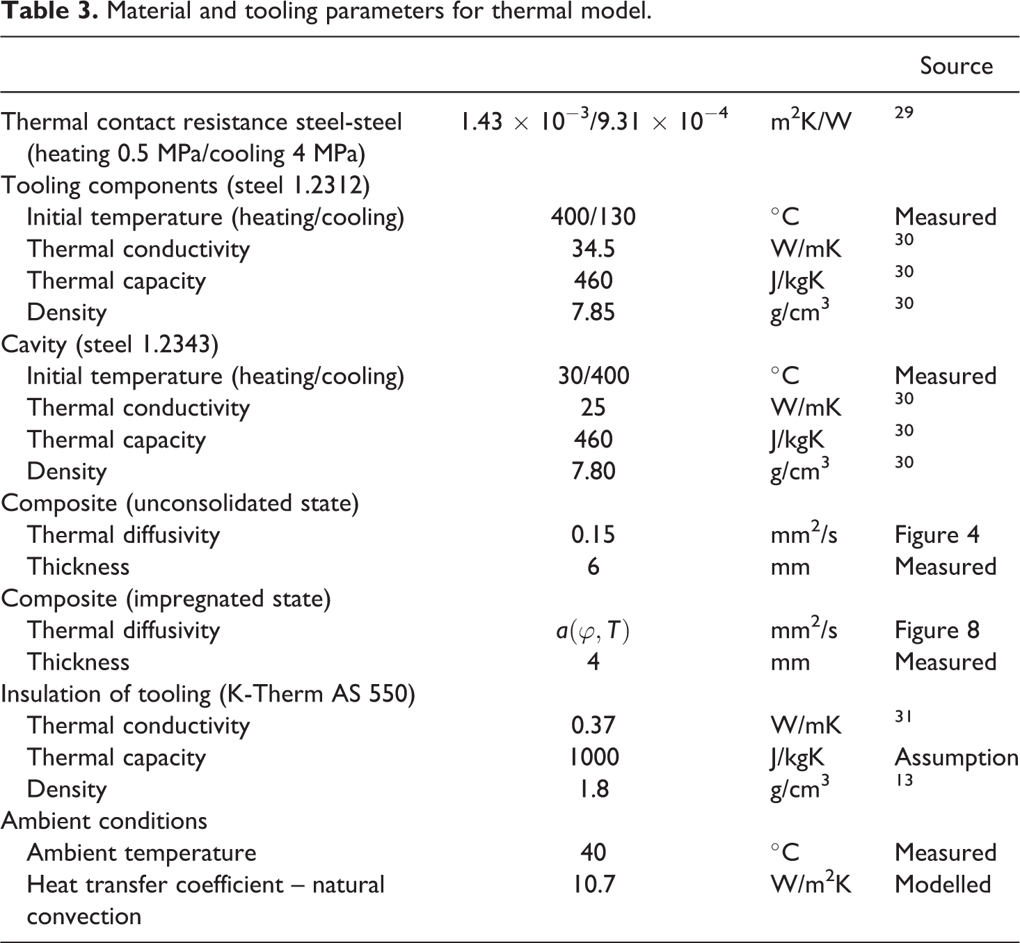
In the following section, the determined data are used for modelling the thermal characteristic of the composite being processed in the isoforming process. The model considers the unimpregnated dry textile inside the cavity, containing 16 single plies. The textile is heated by conduction while being placed inside the cavity, where it is compressed between two hot compression moulds. In addition, the solidification step is modelled under the assumption that the cavity is placed between the cold compression tools. Moreover, the model takes the thermal contact resistance between the cavity and the compression tooling into account. Natural convection is also considered and estimated to a value of 10.7 W/m2K, which also corresponds to Brauner. 28 The developed models are solved by an FE analysis using the Ansys toolbox for transient heat transfer. All relevant parameters are listed in Table 3.
Material and tooling parameters for thermal model.
The heating characteristic does not consider material transport during impregnation (matrix flow) and is therefore conservative. Figure 9 shows the resulting temperature curve within the preform during heating and cooling. The temperature curves on both laminate surfaces and in the centre of the preforms are illustrated. As a result, the PEEK melting temperature of approximately 343°C is reached after 5 min. The time until the impregnation temperature (above 380°C) is exceeded takes a total of 7 min 20 s to 8 min 20 s. A homogeneous distribution of the melt viscosity across the preform thickness and thus homogeneous impregnation properties is indicated by the homogeneous temperature distribution. The modelled heating curve predicts that the melting temperature for the entire preform will be exceeded within a period of 300 s. In conclusion, the negligible temperature differences between the preform centre and the preform surfaces during heating and cooling allow the conclusion that the thermal conductivity of the laminate is not a decisive parameter for accelerating the heating or cooling process. Instead, the heat transfer from the isothermal compression tooling through the variothermal cavity (see Figure 3) is the most relevant parameter for the heating and cooling rates.
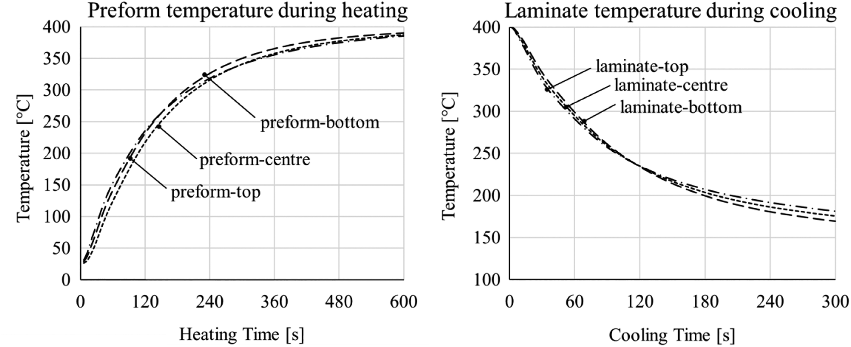
Modelled temperature in laminate during (a) heating and (b) cooling.
Experimental validation of the thermal model by in situ analysis
To validate the heat model, consolidation experiments are performed with the isoforming setup mentioned above. The heating phase lasts 10 min. The temperature of the compression tooling is 400°C. The applied pressure is in dimension of 0.3 MPa during heating to assure that the pressure is low as soon as the first thermoplastic fibres melt. Applying a high pressure at a time, when not all thermoplastic fibres are in molten state, can cause significant carbon-fibre deformations due to high in-plane pressure gradients. After 10 min, the phase of impregnation begins with the application of pressure of 4 MPa for 20 min. Afterwards, the press opens and the cavity is manually transferred in between the cold compression mould to perform the cooling step and to solidify at again 4 MPa applied pressure. After the temperature of the cavity has fallen below the glass transition temperature of 150°C, the cavity is removed and the laminate ejection is performed. To assess the process temperature, a thermocouple measures the temperature of the cavity 6 mm below the preform.
Fibre-optical sensors
For validation of the thermal model regarding the temperature distribution inside the stacking, the integration of glass fibre-optical Fresnel sensors is a promising method to locally identify the time of phase change of the thermoplastic material from solid to fluid phase. This has already been shown by Gaitzsch et al. as a suitable method for analysing the consolidation process of thermoplastic tape materials. 32 The cavity setup and a schematic sketch of the embedded fibre-optical sensor (FOS) are illustrated in Figure 10.
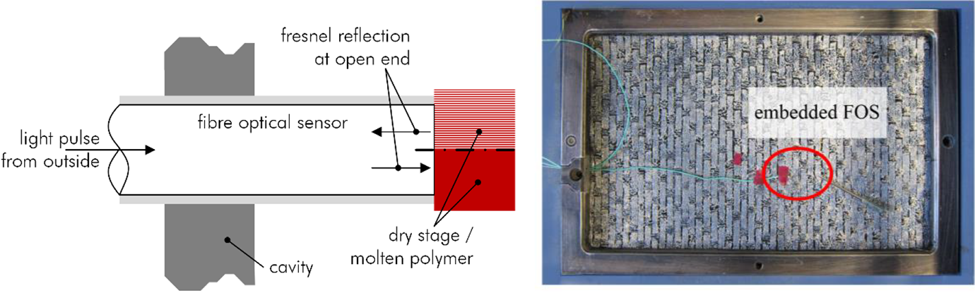
Integration of FOS (a left: scheme and right: FOS beside thermocouples (green) in a powder-coated fabric).
Their measuring principle relies on the reflection of light at the cleaved end of an embedded optical fibre. Depending on the surrounding material covering the open end, the reflection spectra and especially the intensity change of the spectra are affected. During melting of the thermoplastic polymer, the open end of the glass fibre sensor is covered with melt, which consequently influences the reflection intensity. By applying this method, a local detection of the point of melting of the polymer is feasible, which, in turn, provides information about the reliability of the heating and cooling model.
Standard single-mode telecommunication fibre pigtails with a cleaved end are utilized as Fresnel sensors in the consolidation experiments. A mechanical cleaver is used for the cleave. The acrylate coating of the fibre sensors is mechanically removed over a length of around 2 cm by a Miller tool and cleaned with a tissue impregnated with isopropanol before cleaving. The signal is determined by a commercial software Enlight by Micron Optics and subsequently the received wavelengths and their intensity are interpreted and displayed by a MATLAB script.
Four FOSs are prepared and embedded into the preform, which contains 16 single plies. The diameter of the FOS is 125 µm, which does not significantly interfere with the impregnation process. The positions of the sensors are at the preform surface and between plies no. 2–3, 4–5 and 6–7. An overview about the four sensor locations (Ch1–Ch4) is given by a computed tomography (CT) scan in Figure 11 made by a phoenix v|tome|x m (research edition) CT. To minimize undulations of the Fresnel sensors, they are aligned into the direction of one ply they are lying on.
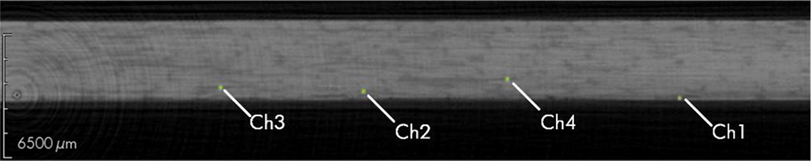
CT scan of positions of FOS in consolidated laminate.
Results and discussion
The resulting process diagram, the reflection spectra and the reflected optical intensities are displayed in Figure 12. Note that channel 1 of the Fresnel sensors had a defect during the process, which is the reason it is not shown here.
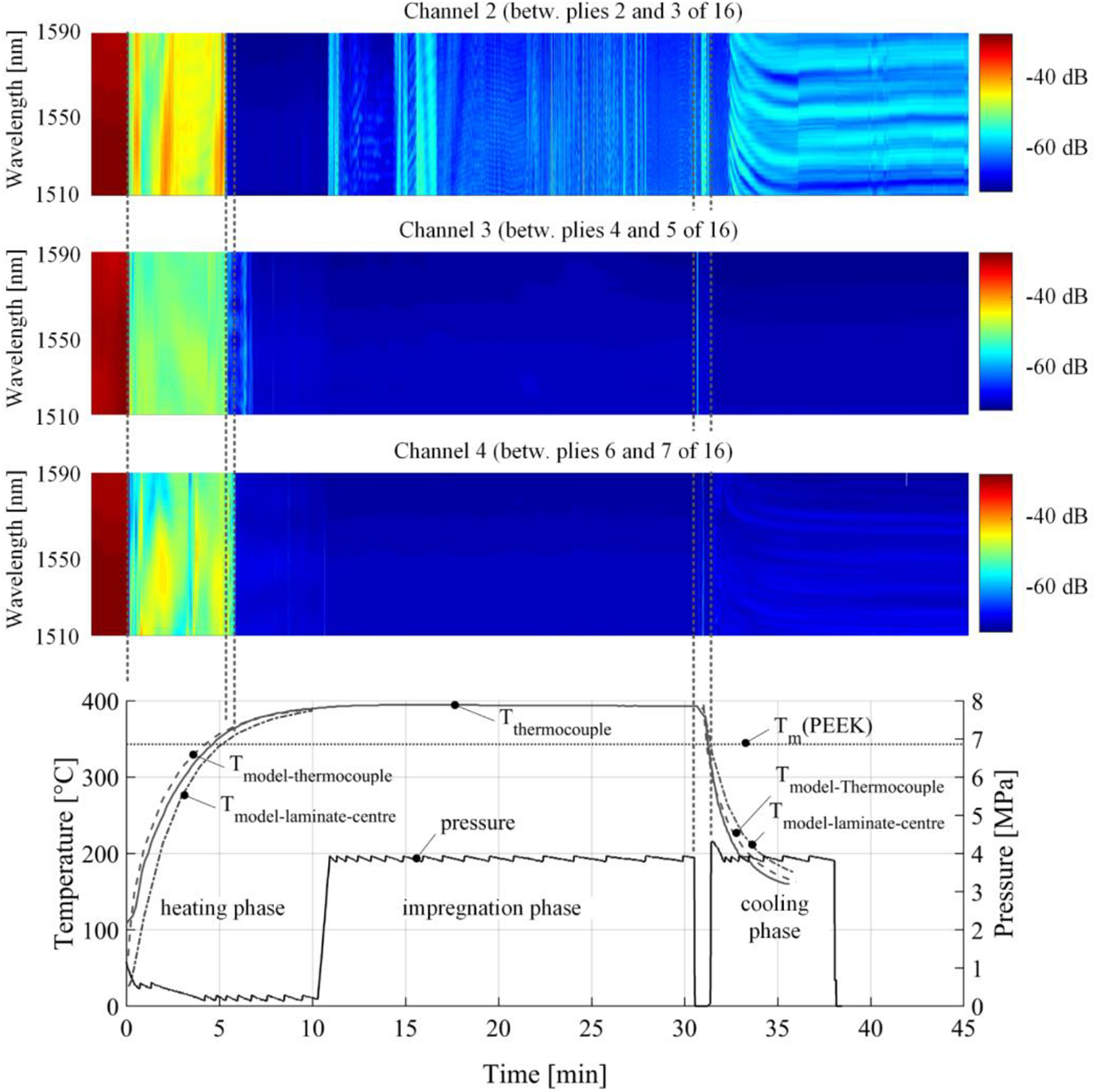
Process diagram with the response of embedded FOS (top) and process parameters. FOS: fibre-optical sensor.
First, the correlation between modelled and measured temperatures at the thermocouple position is determined. After a period of 7 min, the processing temperature of 380°C is reached at the thermocouple, which is inside the cavity and 6 mm below the preform. This is in good agreement to the prediction by the model. Thus, measured and modelled temperatures correlate here for the heating phase at the thermocouple position.
Also, during the phase of cooling, the modelled temperature is in good accordance with the assessed data measured by the thermocouple. The temperature range between 280°C and 220°C is covered in 54 s according to the model and in 48 s, according to the assessed data for the thermocouple position. Consequently, the cooling rate is between 66 K/min and 75 K/min. This temperature section is of particular interest, as crystallization takes place predominantly here according to the DSC analyses carried out by the authors. The good correlation of the thermal model and the assessed data confirm the assumptions about the estimated thermal contact resistance at the interfaces of the compression moulds and the cavity.
By interpreting the obtained data from the embedded glass fibre sensors, the heat model for the heating characteristic within the preform with respect to the impregnated laminate is now to be validated. The predictions for the time the melting point is exceeded are compared with phase changes of the polymer, which are detected by the FOSs.
Interpreting the reflection spectra first of all shows an appropriate detectability of drastic changes inside the preform. For all three channels, the first application of pressure during closing the tooling is observable by a change of the reflected optical power approximately from 30 dBm to 50 dBm. Also, the point of first contact of thermoplastic fluid onto the open end of the Fresnel sensor is clearly detectable. At this point, the reflected power drops below 60 dBm (blue area). While the thermal model predicts that the melting point will be exceeded after 5 min 8 s, the measured data show 5 min 50 s required time until passing the melting point at the preform centre between plies 6 and 7. Note that a sharp transition between solid and fluid phase is difficult to detect, as the melting of semi-crystalline PEEK is a continuous process covering the temperature range between approximately 335°C and 348°C. Furthermore, heat transfer in dry textiles is a pressure-dependent process, so both those factors might cause the discrepancy between modelled and assessed data. Summarizing, the model and the input parameters show a satisfactory correlation with the process data during heating. Moreover, the time shift in the intensity change between channel 2 and 4 is in dimension of 25 s. This underlines the fast heat transfer from the surface region to the preform centre.
During the phase of impregnation, the process is governed by impregnation on roving-scale. This means that all carbon fibre rovings are assumed to be embraced by the thermoplastic melt and penetration into the roving and in between the filaments of the roving occurs. Only channel 2 shows variations in its spectra, which presumably is caused by voids, namely residual air at the open end of the sensor. Channels 3 and 4 do not show any spectral or intensity change. None of the sensors allows an interpretation of the progress of impregnation, as soon as their faces are covered with the thermoplastic melt. Only voids formatting at the sensors face seem to be detectable.
The transfer phase between the hot and the cold compression tooling and the corresponding pressure drop is reflected by small and short-time intensity changes of the sensor response. A pressure drop can cause a dissolution of air or re-expansion of voids, which would be detectable at the sensor-free end. This presumably occurred in the impregnated laminate. However, the subsequent application of pressure for the cooling phase delivers the same reflection intensity as before the pressure drop. Consequently, the assumption that the pressure drop during the isoforming process does not affect the formation of voids, which is supported by the experiments.
In the cooling phase, channels 2 and 4 show a reaction after 32 min at 280°C. The wave shape of channel 2 and 4 can be related to crystallization or shrinking. A reliable interpretation, however, requires further experiments. Channel 3 shows no reaction, indicating a defect. After approximately 5–6 min of cooling, the spectra become stationary again, which allows the interpretation of a stationary material condition at constant temperature. The sensor values are now lower than during the initial heating phase, because the cleaved fibre end face now is in contact with solidified thermoplastic polymer. In this case, the Fresnel reflection intensity is lower than for a contact with air at the cleaved end face, which was the case in the initial heating phase.
Conclusion and outlook
The objective of this article was to widen the knowledge about hybrid textiles in terms of their thermal behaviour during compression moulding. Therefore, a hybrid textile consisting of thermoplastic and reinforcing fibres in shape of an NCF with side-by-side arrangement was introduced including an investigation about its properties, which affect the thermal heat transfer during compression moulding. Based on these data, a thermal model was developed for describing the isoforming consolidation process, which enables fast heating and cooling. To validate the thermal model measured data provided by thermocouples and embedded glass, FOSs were taken into account.
Concerning the thermal model for predicting the performance of the isoforming process and the inner preform/laminate heating characteristic, in particular, the modelled temperatures showed a satisfactory agreement with the measured data points. Moreover, the cooling characteristic of the tooling was successfully predicted. The temperature inside the laminate could be modelled based on temperature-dependent material data.
Generally, the analysis of the heating characteristic is substantially supported by glass-FOSs. A reliable determination of the time of melting is possible by means of the embedded fibre sensors. The interpretation of the reflection intensity during impregnation does not deliver adequate data for the analysis of the impregnation process. Additionally, the cooling behaviour should preferably be investigated with other methods, for example, fibre Bragg grating sensors, which help to measure strains caused by shrinkage during the cooling process or induced by crystallization. Embedded thermocouples could be another alternative, however, their limited reliability against high temperatures and their large diameters with respect to the glass-FOSs is disadvantageous.
In conclusion, the thermal behaviour of a hybrid textile during compression moulding can be modelled accurately. Moreover, it was shown that FOSs are helpful for obtaining information about the local aggregate state and about the presence of voids inside a composite laminate.
Footnotes
Funding
The author(s) disclosed receipt of the following financial support for the research, authorship, and/or publication of this article: The authors are grateful for the financial support provided by the Federal Ministry for Economic Affairs and Energy (BMWi) on basis of a decision by the German Bundestag within the framework of the national aeronautical research program V and the project HyFrame (LuFo V-3) under the grant number 20W1704F and the financial support by the German Research Foundation (DFG: Deutsche Forschungsgemeinschaft) under the contract number HE 2574/31-2.