
Abstract
Thermal aging affects polymer ignition and flame spread process by changing the polymer kinetic parameters. Polyethylene (PE) with 0.15 mm thickness insulated by copper core of 0.5 mm diameter was used in this experiment. The PE was preheated under different temperature and heating time. Wires which have experienced thermal aging at 130°C for 30 and 200 h display higher crystallinity and pyrolysis temperature. However, the crystallinity and pyrolysis temperature decrease of wires, which experienced thermal aging at 150°C for 30 and 200 h by the results of thermogravimetric analysis and differential scanning calorimetry tests. The ignition experiment results highlight the ignition delay exhibiting “U” type with pressure. Chemical kinetics controls the ignition delay in lower pressure region, and the heat transfer controls the ignition delay in higher pressure region. The region controlled by chemical kinetics is larger for the wire with higher crystallinity and pyrolysis temperature. The flame spread experiment results show that the flame area relays more on flame length for the wires with lower crystallinity and pyrolysis temperatures, while wires with greater crystallinity and higher pyrolysis temperature depend more on flame height.
Introduction
Studying wire combustion not only makes sense in daily life and industrial production but also has great significance for fire safety in aerospace vehicles. Fire often occurs at low pressures such as at high altitude areas like Tibet, airplanes, and spacecraft. Some researchers have studied the effect of ambient conditions on wire ignition and flame spread. Yuji et al. 1 have proposed two differently driven models for flame spread: the “wire-driven” mode for polyethylene (PE)-insulated iron wires and “flame-driven” mode for PE-insulated nichrome wires. Shuhei et al. 2 have found that microgravity was conducive to increasing the probability of ignition. Xinyan et al. 3 have found that the wire was easier to ignite at higher O2 concentration and pressures. Hu et al. 4 have experimentally proved that the flame spread rate (FSR) of the electric wire with copper core showed “U-typed” with inclination angles. In addition, they offered a simplified flame spread mode to explain the phenomena. Lu et al. 5 have suggested that the heat delivered from the flame played a dominant role in the flame spread process. Convective and radiative heat transfer terms increase as pressure done.
Up to now, scholars have only fully considered the impact of the surroundings in fire study but neglected the effect of long-term service of aging cable on fire. 1 –5 Aging causes cable insulation deterioration and irreversible changes in the insulation kinetic parameters, 6 –8 which have a significant effect on cable fire behavior in occupational settings, residential houses, aircraft, and space cabin. Therefore, to improve the fire safety, the effect of aging on ignition and flame spread of typical polymer-insulated copper wires under varied pressure merits deep understanding.
Some research findings expressed that aging leads to insulation deterioration and irreversible changes in insulation kinetic parameters 9 –11 that have a significant effect on the cable fire behavior. While the combined effect of thermal aging and the external environment on wire ignition and flame spread remains unclear. The in-depth study of ignition and flame spread of aged PE must be supplemented. Ignition delay time is an index often used to evaluate reactant flammability 12 and it is useful to predict flame spread tendency. In addition, flame spread and shape reflect fire hazard.
Motivated by the above reasons, this work not only considers the influence of external environment on ignition but also takes into account the thermal aging factor in the actual situation, which provides an experimental and theoretical basis for the fresh ideas of fire safety.
Experiments
According to Boukezzi et al., 13 the crystal perfection of polymer increased first and then decreased when the heating temperature is lower than its melting temperature. However, the degree of crystallinity initially remains before decreasing rapidly when the heating temperature is higher than the melting temperature. The melting temperature (T m) of PE is 135°C. 14 So, the electrical wires are pretreated in constant temperature heating cabinet at 130 and 150°C in this article. Table 1 shows the PE heat treatment conditions and abbreviation numbering. The thermogravimetric analysis (TGA) and differential scanning calorimetry (DSC) tests are utilized to obtain the pyrolysis temperature (T p) and crystallinity (C r) value of the aged PE and unaged PE. These parameters are used to analyze the ignition and flame spread experiments.
The heat treatment conditions for the samples.
The experiments are conducted in a horizontally placed cylindrical cabin with a diameter and a length of 40 cm. The pressure range of the cabin is from 0.3 kPa to 100 kPa (±0.01 kPa). To reduce noise interference, the cabin remained in a quiescent state during the experiment. PE with a thickness (δ p) of 0.15 mm insulated with 0.5-mm diameter (d c) copper (Cu) core. The sample length is 22 cm. The 15-mm length coil heater is supplied with a constant power supply of 75 W. As soon as the flame begins to propagate, the power supply is cut immediately. The diameter of coil igniter (VAPOR TECH A1) is 0.51 mm. The sample wire is placed at the center of the coil igniter. The distance between the coil igniter and the sample holder is 5 mm. To avoid the influence of igniter, the steady stage is chosen to calculate the flame spread velocity, which is usually 40–50 mm away from the coli igniter. The experimental setup was placed on the sample holder in the center of the cabin. Figure 1 shows the experimental setup.
Experimental apparatus.
The ignition and subsequent flame spread are recorded by a APS-C Nikon D3200 Digital SLR camera (30 frames s−1, ISO 500) to track the flame position by a steel ruler on the sample holder, and video images were processed by the MATLAB program. The average mass loss is measured by an analytical balance (±0.1 mg). To reduce error margins, all experiments are repeated at least three times. To understand the experimental results intuitively, this article takes the turning pressure as the basis, so-called lower pressure and higher pressure are compared with turning pressure.
Results and discussion
Kinetic parameters
The changes in the microstructures of materials caused by thermal aging include chain fission, free radical recombination, carbon–hydrogen bond fission, and hydrogen extraction. These degradation changes lead to macroscopic changes in material kinetic parameters, such as pyrolysis temperature and crystallinity. 15 –17
The TGA results at heating rates of 5°C min−1 in air atmosphere at 100 kPa are selected to obtain the samples’ pyrolysis temperatures. Pyrolysis temperature (T p) results of (a) 130/30, (b) 130/200, (c) origin, (d) 150/30, and (e) 150/200 are shown in Figure 2.
TGA results of PE at a heating rate of 5°C min−1 in air at 100 kPa (a) 130/30, (b) 130/200, (c) origin, (d) 150/30, and (e) 150/200.
In general, the higher the degree of crystallinity of the sample, the better the overall organization of lamellae within it. The DSC test results can be used to calculate the crystallinity.
18
The degree of crystallinity (C
r) of the sample is calculated by the following equation:
The T p and C r in the samples.
T p: pyrolysis temperature; C r: relative crystallinity.
According to Table 2, both the pyrolysis temperature (T p) and relative crystallinity (C r) for 130/30 and 130/200 increase compared with the original wires. Both T p and C r decrease for 150/30 and 150/200. In addition, they conformed to the following order: T p (130°C, 30 h) > T p (130°C, 200 h) > T p (origin) > T p (150°C, 30 h) > T p (150°C, 200 min), and C r (130°C, 30 h) > C r (130°C, 200 h) > C r (origin) > C r (150°C, 30 h) > C r (150°C, 200 h).
Ignition delay time
Figure 3 shows the ignition delay times (t ig) of wires with varied pressures (p). The turning pressure is defined as the pressure to which the smallest t ig corresponds. The t ig exhibits U-typed by pressures for the wires. The ignition delay time of the different wires is ranked as follows: t ig (130 °C , 30 h) > t ig (130 °C , 200 h) > t ig (original) > t ig (150 °C , 30 h) > t ig (150 °C , 200 h). Compared with the original wire, the electrical wires of 130/30 and 130/200 require longer time for ignition, while wires of 150/30 and 150/200 need shorter ignition time. This is because 130/30 and 130/200 wires with the higher T p and C r are more stable than that of 150/30 and 150/200.
Ignition delay time of the wires with varied pressures.
Solid ignition is determined by the pyrolysis of solid combustibles, pyrolysis gas mixing with oxygen, and the gas-phase chemical reaction of the combustible gases. The solid is heated to a temperature, which is sufficiently high so as to produce pyrolysis gases. These pyrolysis gases mix with a suitable amount of oxygen to form combustible gases. The combustible mixture triggers the gas-phase induction process so as to ignite nearby gases. For sustained burning, enough pyrolysis gases must be produced so that the heat release rate is great enough to overcome the heat losses. 19 Pyrolysis strongly depends on the temperature, while the reaction speeds up as the temperature increases. 20 The ignition delay time (t ig) can be separated into pyrolysis time (t py) and chemical induction time (t in) according to Fernandez-Pello. 20 The pyrolysis time of thermally thin material exposed to external heat flux is expressed as follows:
where
In this article,
Based on the above analysis, the pyrolysis time (t
py) decreases with the decreasing ambient pressure (
The chemical induction time can be expressed as follows: 19
where a is the buoyancy induced stretch rate, T
pilot is the pilot temperature, while
Thus,
where c is a proportionality constant, E is the gaseous reaction activation energy, n is the reaction order,
Based on equation (5), the induction time (t
in) decreases with the increasing ambient pressure (
For the same solid, that is, at the same pyrolysis temperature (T p), the ignition delay time is controlled by the chemical kinetics and the heat transfer. Thus, the schematic description of the solid ignition time is shown in Figure 4.
Schematic description of how solid ignition time varies with pressure (turning pressure P t can also be described as the boundary between “chemical kinetics controlled” and “heat transfer controlled”).
Based on the above analysis and Figures 3 and 4, it can be concluded that the low-pressure region’s ignition delay is dominated by chemical kinetics, which causes ignition delay time to decrease alongside pressure. In the high-pressure region where the ignition process is controlled by heat convection transfer, ignition delay time increases alongside pressure as convective losses increased. Therefore, the ignition delay exhibits “U” type behavior with pressure. Moreover, the lower T p and unstable structure C r reduce the ignition delay time by decreasing both t py and t in.
In addition, based on Figure 3, the pressure turning point for ignition delay time can be ordered as follows: Pt (130°C, 30 h) > Pt (130°C, 200 h) > Pt (original)> Pt (150°C, 30 h min) > Pt (150°C, 200 h). The turning pressure increases with T p and C r. As structural stability increases, the ignition delay controlled by chemical kinetics regime increases.
Mass loss and flame spread rate
The heat release rate is the key factor determining fire hazards. Higher heat release rates are associated with greater pyrolysis rates and faster FSRs. 21,22 Figure 5 shows the mass loss (a) and FSR (b) of different wires at various pressures, revealing that mass loss and FSR increase with pressure. Moreover, the wire with the lowest T p and C r exhibits the highest mass loss and FSR. According to Niioka and Takahashi, 21 Burke Michael, 23 and Fang et al., 24 increasing pressure causes the oxygen proportion to elevate the combustion gas, which generates a more violet chemical reaction. Therefore, burn-out efficiency increases alongside pressure. The samples with lower T p absorb less heat during the PE melting process, increasing melting layer thickness. 5 Thus, the mass loss and FSR of 150/30 and 150/200 are larger than that of 130/30 and 130/200.
Mass loss and FSR for wires at various pressures.
Flame area and height/length
Flame size is directly correlated with the heat release rate. 25 Figure 6 shows that the flame area and height are positive with increasing pressure, while flame length is negative with increasing pressure.
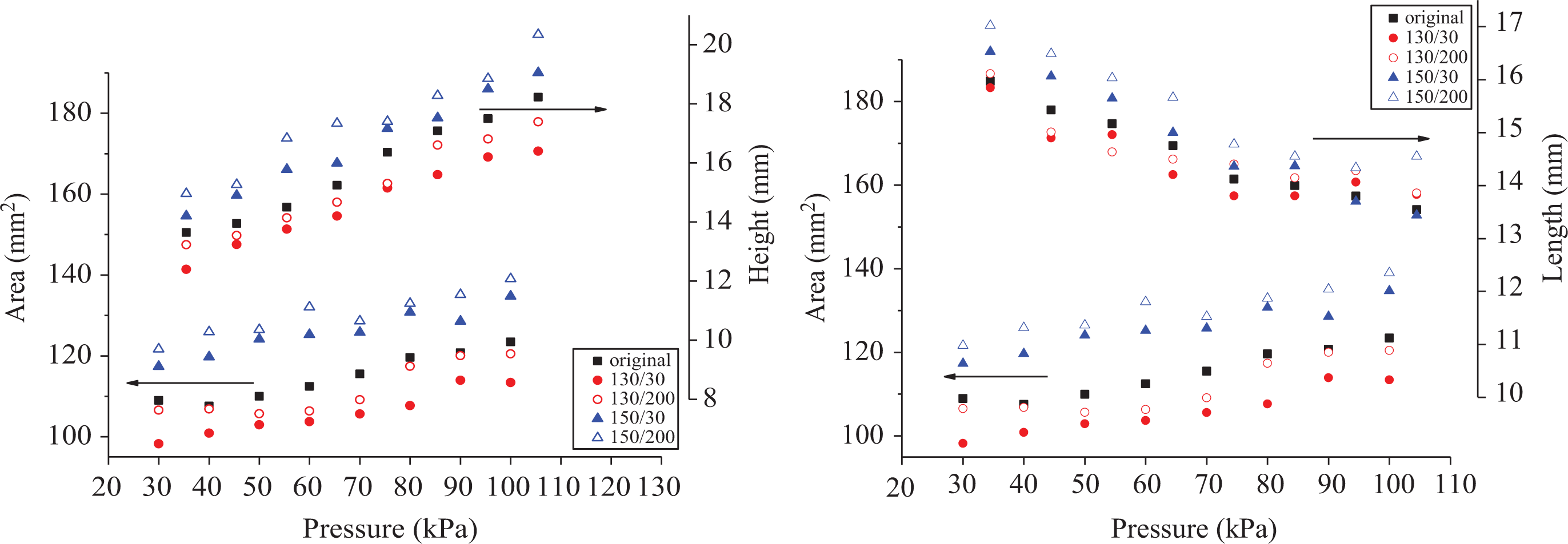
Flame area versus flame height/length.
Flame height is given by
By analyzing the data from Figure 6, the relationship among flame area (A), flame height (Hf ), and length (Lf ) is found (R 2 helps to measure the fitting results):


Flame area is determined by flame length and flame height. Following on from the above discussion, height is positively correlated with pressure for diffusion, while the length is negatively correlated with pressure for the chemical reaction. According to exponent value, the speed of flame area increase relies more on a slow length decrease for 150/30 and 150/200. Meanwhile, for 130/30 and 130/200, flame area depends more on a faster increase in height.
Conclusion
In this work, wires that experienced a temperature of 130°C for 30 and 200 h have higher pyrolysis temperatures and crystallinity. However, wires that experienced 150°C for 30 and 200 h display lower pyrolysis temperature and crystallinity according to the TGA and DSC tests. In the low-pressure region, chemical kinetics dominates ignition for its longer chemical induction time, which causes the ignition delay time to decrease with pressure. Moreover, in the high-pressure region, heat convection transfer controls the ignition process, while the ignition delay time increases with pressure as convective losses increase. Thus, ignition delay exhibits “U” type with pressure, while the region controlled by chemical kinetics is larger with increasing T p and C r. Compared with the wires which have a lower T p and C r, those wires with high T p and C r require more time for ignition and their mass loss and FSR are smaller. The increasing flame area relays more on the slowly decreasing length of the wires with lower T p and C r, while the flame area for the wires with higher T p and C r depends more on the faster increase in height.
Footnotes
Acknowledgement
The authors give great thanks for the valuable suggestions by Dr Xinyan Huang from Hongkong Polytechnic University.
Funding
The author(s) disclosed receipt of the following financial support for the research, authorship, and/or publication of this article: This work was sponsored by the National Natural Science Foundation of China (51576186 and 51636008), NSFC-STINT joint project (USTC-Lund University), Key Research Program of the Chinese Academy of Sciences (No. QYZDB-SSW-JSC029), and Fundamental Research Funds for the Central Universities (WK2320000034 and WK2320000036).