
Abstract
This article reports joining feasibility of polylactic acid-polyether ketone ketone-hydroxyapatite-chitosan composite scaffold with consumable tool in friction stir spot welding (FSSW) as a novel process. Also, investigations have been made for mechanical, thermal, and morphological characteristics of the joints prepared. The results for joint strength are supported with axial/transverse force and interface temperature measurement for bone scaffolds. The FSSW process parameters, namely rotational speed, pin depth, and stirred time, have been varied to correlate the changes in force and temperature with mechanical and morphological properties. The results of the study highlighted that ultimate tensile strength (6.57 MPa) and flexural strength (139.2 MPa) were obtained best at 800 r/min rotational speed and 20 s stirring time with 2.5-mm pin depth.
Introduction
Solid-state welding or friction stir welding (FSW) was initially developed for joining of aluminum and its alloys. 1 Nowadays, this process gets significant importance in joining of polymers too. Good mechanical strength, low thermal stress, and acceptability for automation increased the importance of FSW in today’s industry. 2 The heat is generated due to friction between the rotating tool/pin and workpiece. Conventionally, in FSW, a rotating tool in the form of cylindrical pin travels with some penetration along the thickness. 3 The strength and quality of the welding joint are greatly influenced by welding parameters. 4 It has been reported in case of nanocomposites that surface layer of a composite at the welding zone can be suitably controlled. 5 Although fastening is accepted process for joining for the sake of simplicity, in high load applications, welded joints are more preferred. This may be due to the fact that fastening increases the stress concentration factor in the joined parts by the creation of hole, also weight of joint is significantly increased due to fasteners weight. 6
In FSW, it is difficult to obtain higher mechanical strength and desired surface quality. To tackle this problem, some researchers have modified FSW tool (consisting of a rotating pin, a stationary shoulder (shoe), and a heating system inside the shoe). Rotational speed of the pin, tool traverse speed, and shoe temperature were considered as varying parameters in this study and good results for improvement in flexural properties were observed. 7 As compared to metals, polymers have low melting temperature, less hardness, small solidification time, and less thermal conductivity, thus making FSW useful process in joining of thermoplastics. In FSW, along the tool feed, two different regions are observed: transverse side (pin rotation and feed are in same direction) and retarding side (pin rotation and feed are in opposite direction). 8 Due to the energy consideration, the demand for strength to weight ratio in automotive industry and in space sectors is significantly increasing. This demand is fulfilled by the lightweight silicon carbide and aluminum oxide-based reinforced polymers, which replace heavy metals, such as cast iron and steel. 9 The friction stir spot welding (FSSW) is an improved version of FSW, which gives good results mainly for joints of small width. In the case of FSSW, the feed of the tool along the transverse direction is eliminated and the welding process is performed on a single spot. 10 Previous studies have reported that welding defects like porosity and weld line cracks are better addressed in the case of FSW. 11,12 Goushegir et al. investigated the microstructure of aluminum (AA2024) and carbon fiber-reinforced polymers in single lap joint. It has been observed that at higher revolutions/min, the spot joining area is found to be increased, which increases the strength of lap joint. 13 The defects in FSW can be removed up to a great extent by setting minimum threshold in axial force and above some limiting rotational speed. It was reported that rotational speed dominates about 74% of the overall welding parameters for reduction in surface defects. 14 Pin depth/profiles greatly affect the mechanical mixing of the two mating plates as well as the seam pattern. The taper cylindrical pin geometry was reported best as compared to grooved cylindrical and cylindrical geometry. Pin inclination angle of 1° showed better result as compared to zero pin angle. 2 At higher speed of rotation due to excess heat, the hardness of polymeric sheet decreases and sheet is unable to withstand the high pressure applied by the tool and sometimes results in permanent deformation along the weld seam. 15 Some studies have reported that tool geometry greatly affects the joint binding ability in FSSW. Triangular pin with concave profile increases the material flow as compared to cylindrical pin and increases the joint efficiency. 16,17 The strength of the weld section is 50% that of base polymer strength in case of FSW of polypropylene and weld toughness found to be increased. 18,19
Some recent studies in FSSW highlighted the effect of pin size on polycarbonate sheets with FSSW process. It has been reported that due to change in tool velocity, two different regions were observed and low velocity region is considered as the main cause of plunging force. It was also observed that tool inclination does not affect the joint properties but pin dimension changes the joining forces. 20 In another study, mechanical behavior of polycarbonate sheets welded by various tool geometries in FSSW process was investigated. Here, the direct relation was observed in shear strength and shoulder diameter. It has been reported that large pin diameter reduces the shear strength. 21 The effect of plunging force in FSSW has been reported in case of thermoplastics. 22,23 Circular pattern was observed in the welding zone at low joining speed and low rotational speed that are due to low pressure of tool, whereas at higher welding speed, more flash was observed due to high welding temperature. 23 Some studies outlined the decrease in mechanical strength at low temperature mainly due to insufficient softening of polymers while FSSW. 22 –24 However, good strength was observed at higher rotational speed but excess rotation removes the material from the joint. 24 The reported literature outlined that FSSW and FSW of metals/metallic alloys, thermoplastic, and thermoplastic composites are commercially feasible. The major advantage of FSW in comparison to FSSW is while seam welding, whereas for spot welding applications, FSSW is a better solution.
The biocompatible polylactic acid (PLA) thermoplastic and its composites have lot of applications in orthopedics, tissue engineering, and restorative dentistry. 25 It has been reported that fused deposition modeling (FDM) has been used for printing polylactic acid-hydroxyapatite-chitosan (PLA-HAp-CS) composite scaffolds at lab scale. 26,27 Commercially, the scaffolds can be 3D printed, but for small maintenance/repair (such as minor surface cracks) on scaffold, joining of thermoplastic composite materials by FSSW may be one of the cost/time effective solutions. This research work is an extension of work reported on HAp- and CS-reinforced PLA-based biocompatible feedstock filament for 3DP of functional prototypes on commercial FDM. 26,27 In this study, a consumable pin profile was used with online measurement of axial/transverse force (using milling dynamometer) and interface temperature (using thermal imaging camera). The process parameters, namely rotational speed, pin depth, and stirring time, have been varied to correlate the changes in force and temperature over mechanical and morphological properties.
Materials and methods
Figure 1 shows the steps involved in the present study for FSSW of PLA-polyether ketone ketone (PEKK)-HAp-CS-based compression molded substrates for investigating the influences of process parameters on mechanical, thermal, and morphological properties.
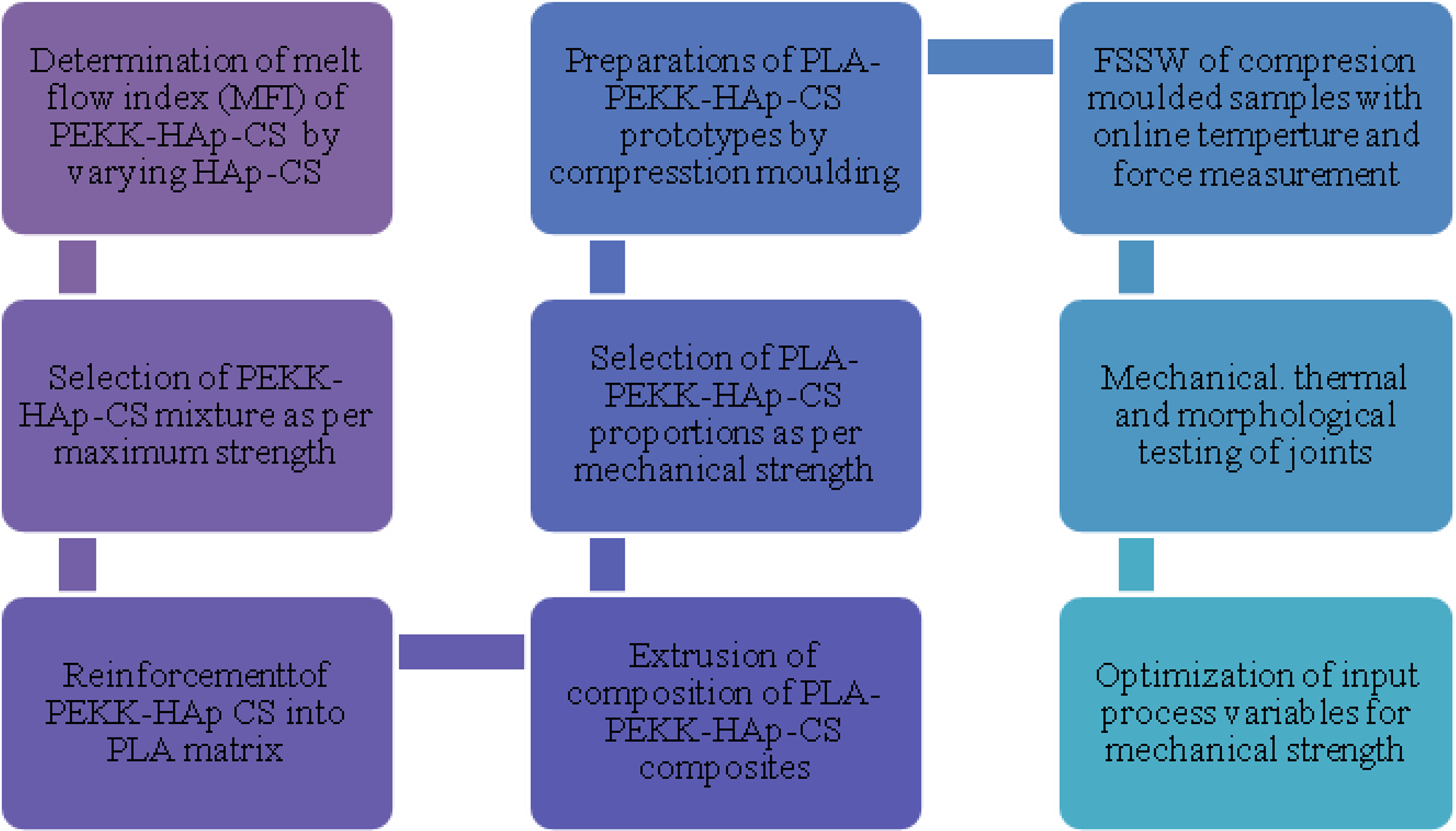
Steps involved for FSSW of PLA-PEKK-HAp-CS composites.
The biocompatible PLA (Φ2–3 mm granules) and reinforcements PEKK (with average Φ100 µm) and HAp and CS (with average Φ50 µm) in powder form have been procured from local market for this study.
Experimentations
Material composition/proportion selection by MFI and screw extrusion
During pilot study, it has been observed that PEKK-HAp-CS compositions/proportions by weight (i. 90% PEKK-8% HAp-2% CS, ii. 92% PEKK-6% HAp-2% CS, and iii. 94% PEKK-4% HAp-2% CS) were having acceptable flow continuity (without choking) as per ASTM D 1238. So, all these compositions/proportions qualified from rheological property (melt flow index (MFI) in g/10 min) viewpoint. After establishing the MFI of selected compositions/proportions, thermoplastic composite was processed on twin screw extruder for the preparation of feedstock filament (at fixed parametric settings: load, 3 kg; screw speed, 100 r/min; and processing temperature, 200°C). The feedstock filaments prepared were subjected to tensile testing as per ASTM D638. Further based on the preliminary experimentations, it has been observed that of the selected PEKK-HAp-CS compositions, 94% PEKK-4% HAp-2% CS attained maximum tensile properties. Hence, this composition/proportion was finalized for further experimentations. Further, to attain best mechanical properties of extruded feedstock filaments, PLA: (94% PEKK-4% HAp-2% CS) has been varied in three weight ratios: A (95:5), B (85:15), and C (75:25) with three temperature ranges: (180–200–220°C) and screw speed: (50–100–150 r/min) as per design of experiment (DOE) based on Taguchi L9 orthogonal array (see Table 1).
Tensile property of extruded feedstock filaments.a
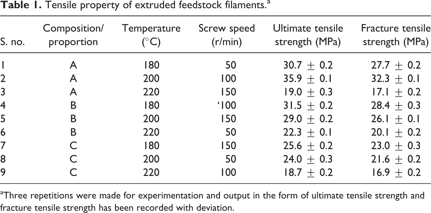
aThree repetitions were made for experimentation and output in the form of ultimate tensile strength and fracture tensile strength has been recorded with deviation.
As observed from Table 1, experimental conditions mentioned in s. no. 2 resulted in maximum ultimate tensile strength and fracture tensile strength; the same settings were used for batch production of feedstock filament wire for the preparation of substrate material for FSSW. Finally, the prepared feedstock filament was put into mechanical shredder for attaining composite granules of Φ2–3 mm, which was reprocessed on cryogenic grinding setup at the temperature of −196°C at 25 Hz for 5 min. The powdered sample so prepared was put into compression molding setup for preparation of substrate for FSSW.
Compression molding
The rectangular sheets of 40 × 30 × 3 mm2 dimension of 95% PLA-5% (94% PEKK-4% HAp-2% CS) (by weight %) composite have been prepared on specimen hot mounting machine (see Figure 2). The cylindrical pins of 40 mm length and Φ4 mm have been prepared with similar process. It should be noted that the compression molding of composite material was performed at 200°C for 5 min time. Figure 3 shows compression molded samples of the required size of rectangular sheets and pin profile for FSSW.
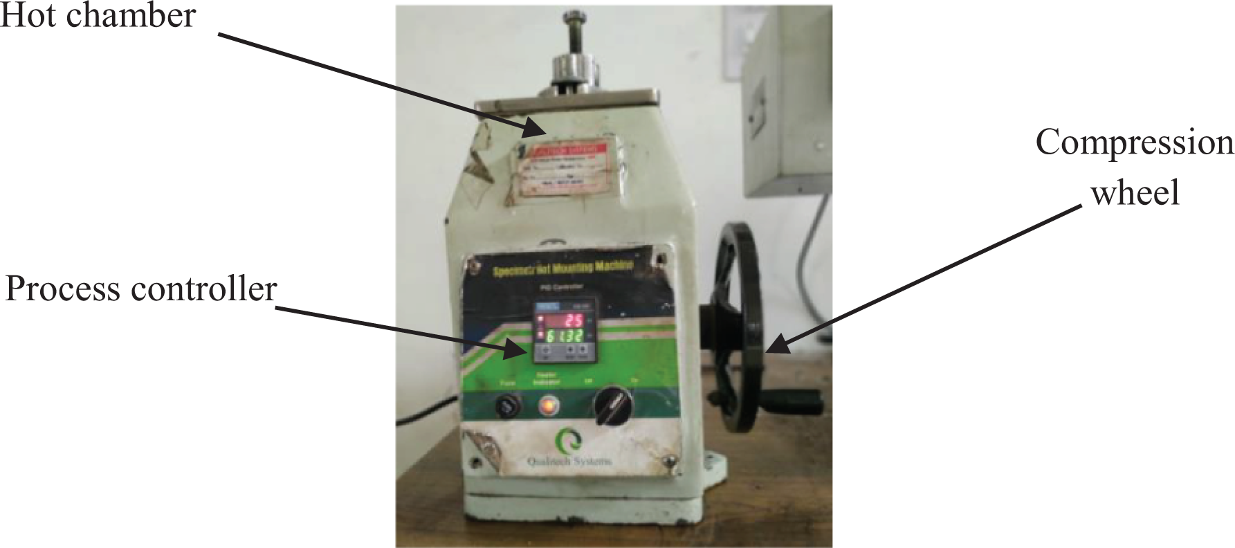
Photographic view of specimen hot mounting machine.
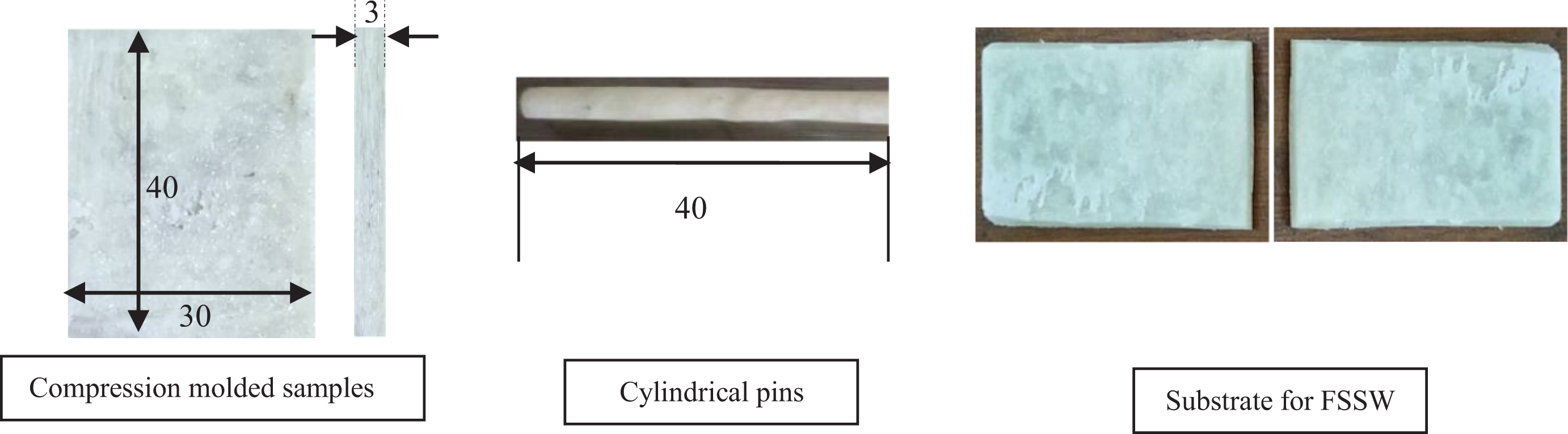
Compression molded substrates: (i) cylindrical pins and (ii) substrates for FSSW.
FSSW
For FSSW, DOE based on Taguchi L9 O.A has been prepared by considering three different levels of rotational speed (800–1200 r/min), pin depth (2.0–3.0 mm), and stirring time (15–25 s) (see Table 2). The levels of input process parameters have been selected as per feasibility of the joints based on preliminary trials. The upper and lower limit of the rotational speed has been selected on the basis of machine constraints and feasibility of joining. The maximum value of pin depth has been selected by considering plate thickness as constraint. Welding/stirring time has been selected to attain proper binding of the joining faces by generating sufficient frictional heat. Figure 4 shows the experimental setup on vertical milling for FSSW.
DOE of FSSW as per Taguchi L9 O.A.a
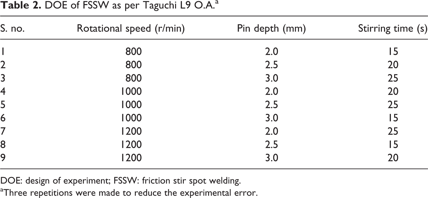
DOE: design of experiment; FSSW: friction stir spot welding.
aThree repetitions were made to reduce the experimental error.
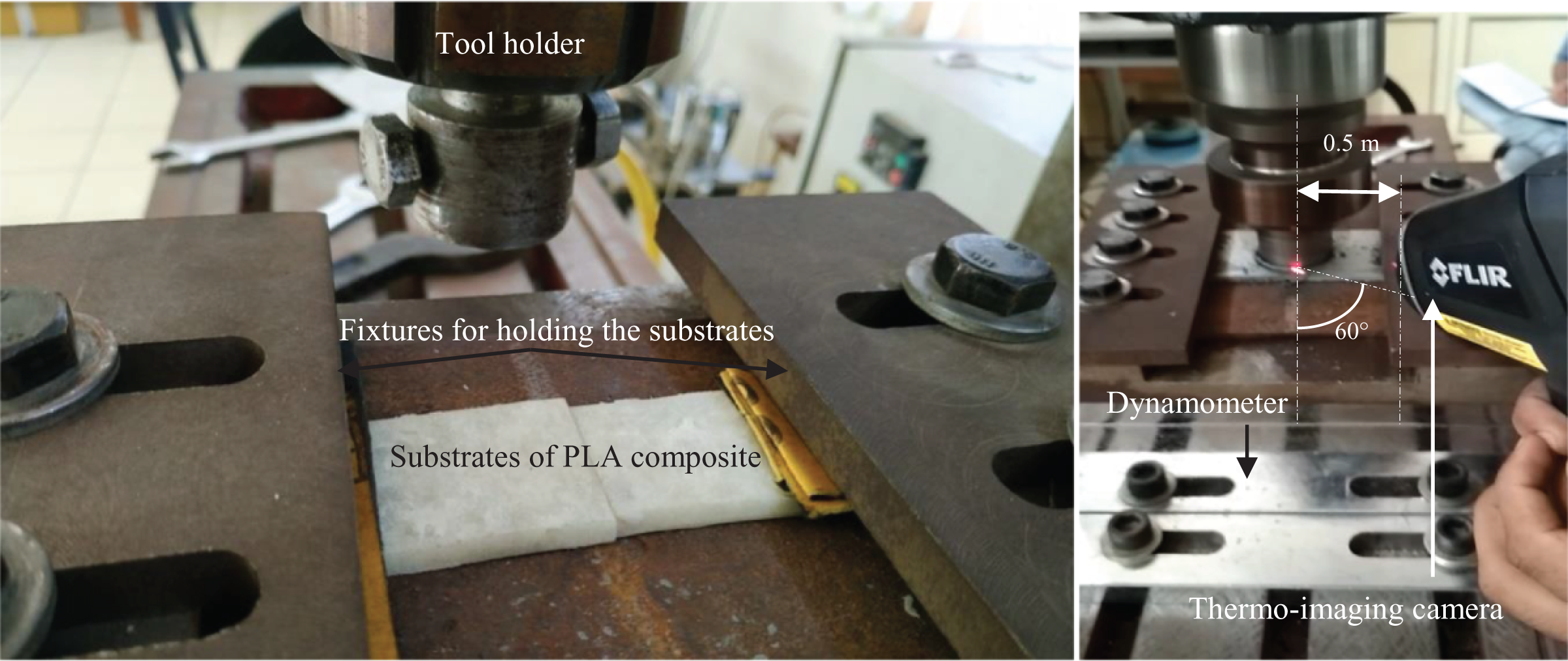
Experimental setup for FSSW.
The welding was performed on vertical milling setup with online measurements of axial and transverse force using milling dynamometer (Company: Industrial engineering instrument, India, Model: Multicomponent digital force indicator, Model: 652) and interface temperature by using thermal imaging camera (Company: FLIR, Model: TG165). Figure 5 shows the joints prepared with the help of FSSW with the use of pin (as a filler material). The circular region is a plastically deformed region that is created due to frictional rubbing between pin holder and upper face of the plate.
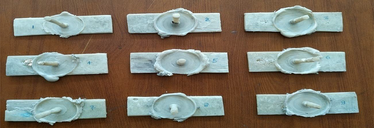
Joints of 95% PLA-5% (94% PEKK-4% HAp-2% CS) sheets using consumable pin (as shown in Table 2).
Results and discussion
Thermal imaging
The results obtained from online measurement of interface temperature suggested that maximum interface temperature has been obtained for sample no. 2 (76.4°C) and minimum for sample no. 5 (43.6°C) (see Figure 6). For establishing the emissivity value of thermal imaging camera, weight proportion of reinforcements and matrix material with their basic emissivity value (based upon literature) has been used. 28 –31 In the present study, the FSSW process has dealt with PLA thermoplastics matrix reinforced with different percentage of 94% PEKK-4% HAp-2% CS. The thermal imaging camera was focused on the joint interface of sheets (substrate) and an average of three emissivity values (for three proportions: A, B, and C as shown in Table 1) has been fixed for experimentations as 0.92.
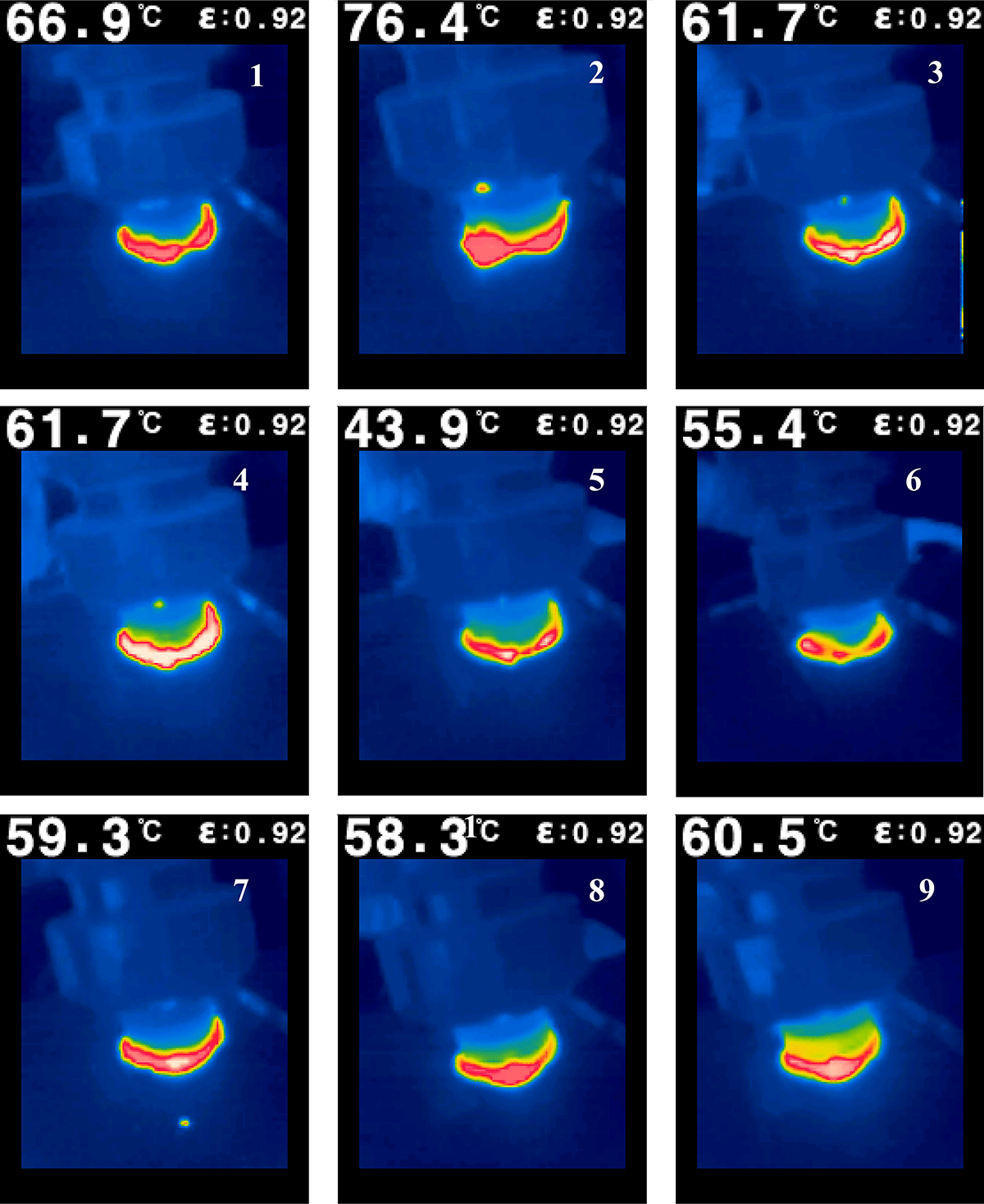
Thermal images of FSSW process.
4.2 Force measurement
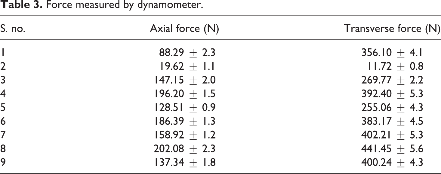
Table 3 shows force measured on axial as well as transverse directions while FSSW. It should be noted that the minimum force is preferred in manufacturing for better stability and process control. The results of the study suggested that minimum force is exerted by sample 2 (axial force: 19.62 N and transverse force: 11.72 N). Similarly, maximum axial (202.08 N) and transverse force (441.45 N) were recorded for sample 8. It should be noted that maximum heat generation was observed in experiment no. 2 (Figure 6). Based on Figure 6 and Table 3, there seems to be some relation between maximum interface temperature and requirement of axial/transverse force. In order to understand this relation, photomicrographs (Figure 7) have been captured for all samples prepared, as shown in Table 2.
Force measured by dynamometer.
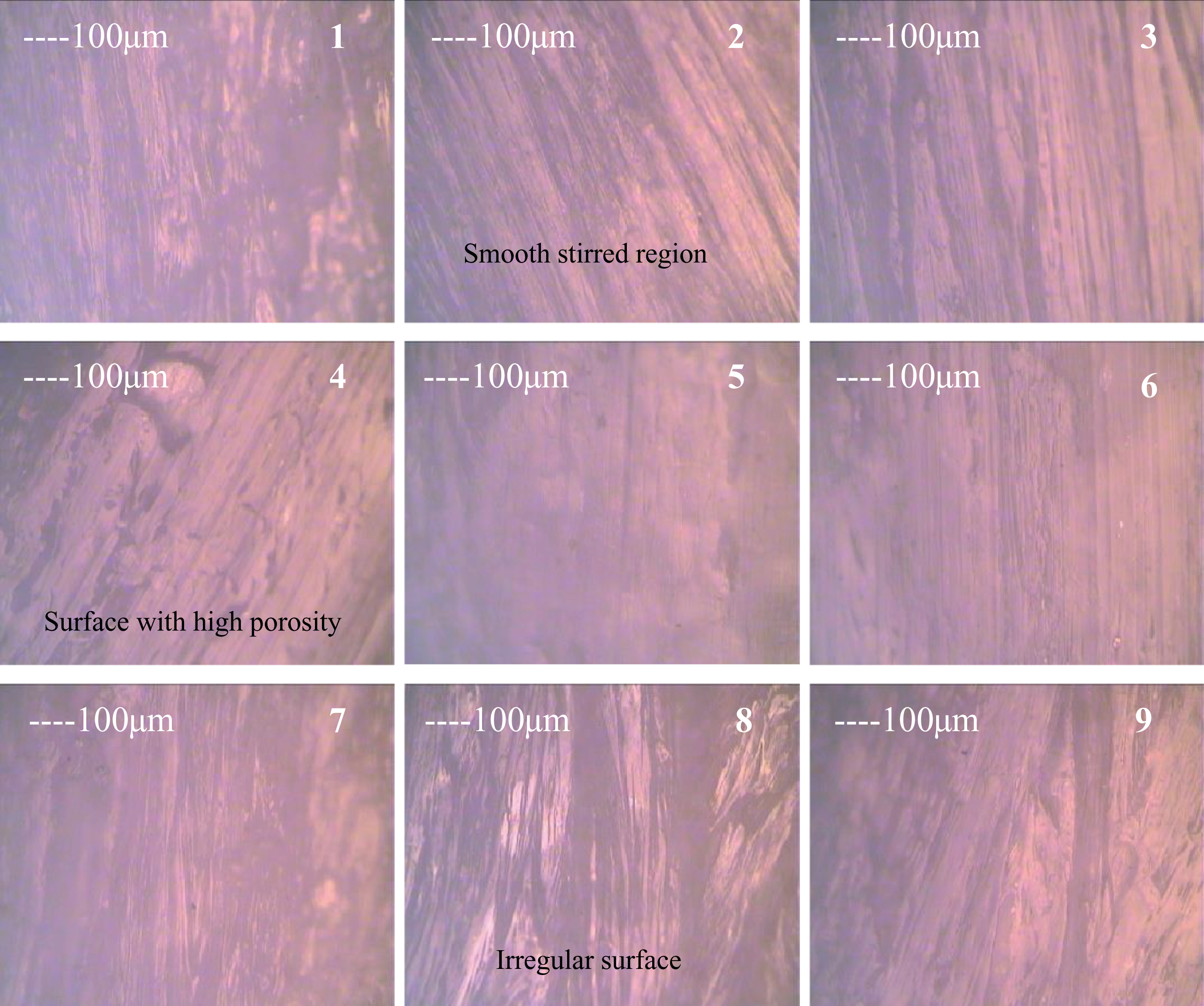
Photomicrographs at ×100 magnification. Note: Morphology of the specimen was investigated with the help of optical microscope (specification; magnification range: ×100–×800; specimen bed size: 200 × 200 mm2; and number of lenses: 4). The samples were analyzed under ASTM E2015–04 (2014) without any etching agent.
Photomicrographical observations
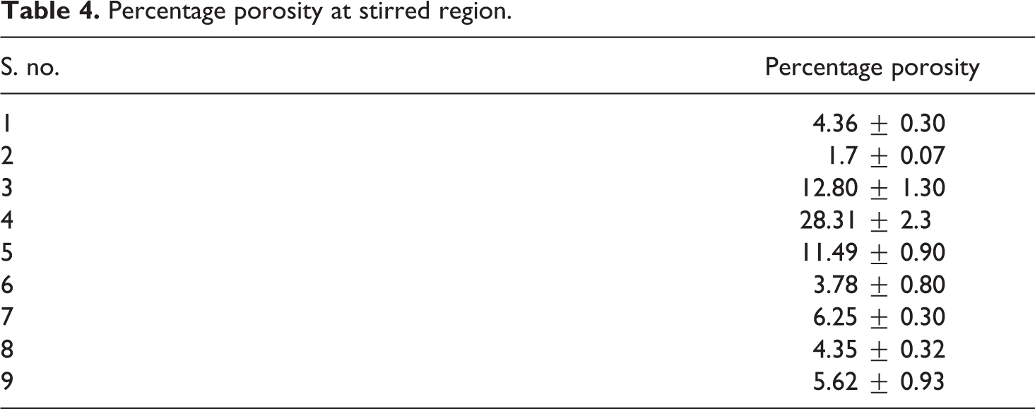
The micrographical observations of all samples are performed at 100× magnification by using metallurgical image analysis software as per ASTM E2015-04 (2014) and ASTM F2150-13. The images obtained from optical microscope were analyzed to investigate the changes in percentage surface porosity of stirred zone (see Figure 7). It has been observed from the photomicrograph of sample 2 that smooth stirred region with less surface porosity was attained, whereas photomicrograph of sample 4 shows nonuniform layers with poros surface. Based on Figure 7, Table 4 shows the average porosity of each joint. The results shown in Table 4 are the average three observations on each joint. It has been observed that maximum porosity was obtained for sample no. 4 (28.31), which is considered at most defected joints. Similarly, the percentage porosity of sample 2 was observed minimum (1.7%).
Percentage porosity at stirred region.
Tensile and flexural strength
The observations made from Figure 6 and Tables 3 and 4 have shown little disagreement among maximum temperature attained, axial and transverse force, and percentage porosity. Based on Figure 6, the best conditions are attained in experiment no. 2 and poor for experiment no. 5, further based on Tables 3 and 4, best conditions are of experiment no. 2 only, but as shown in Table 3, poor condition is for experiment no. 8 and as shown in Table 4, poor condition is in experiment no. 4. So to ascertain the best and poor joining conditions, the joints were subjected to tensile and flexural testing. Based on Table 2, Table 5 shows observed mechanical properties of joints in tensile and flexural testing. It should be noted that maximum tensile strength (ultimate strength: 6.57 ± 0.80 MPa and fracture strength: 5.89 ± 0.76 MPa) and maximum flexural strength (ultimate strength: 139.2 ± 2.70 MPa and fracture strength: 125.27 ± 2.34 MPa) were observed for sample no. 2. Similarly, minimum tensile strength was observed for sample no. 4 and minimum flexural strength for sample no. 6. Based on Table 5, Figures 8 and 9 show stress–strain curve while tensile and flexural testing.
Mechanical properties of FSSW joints.
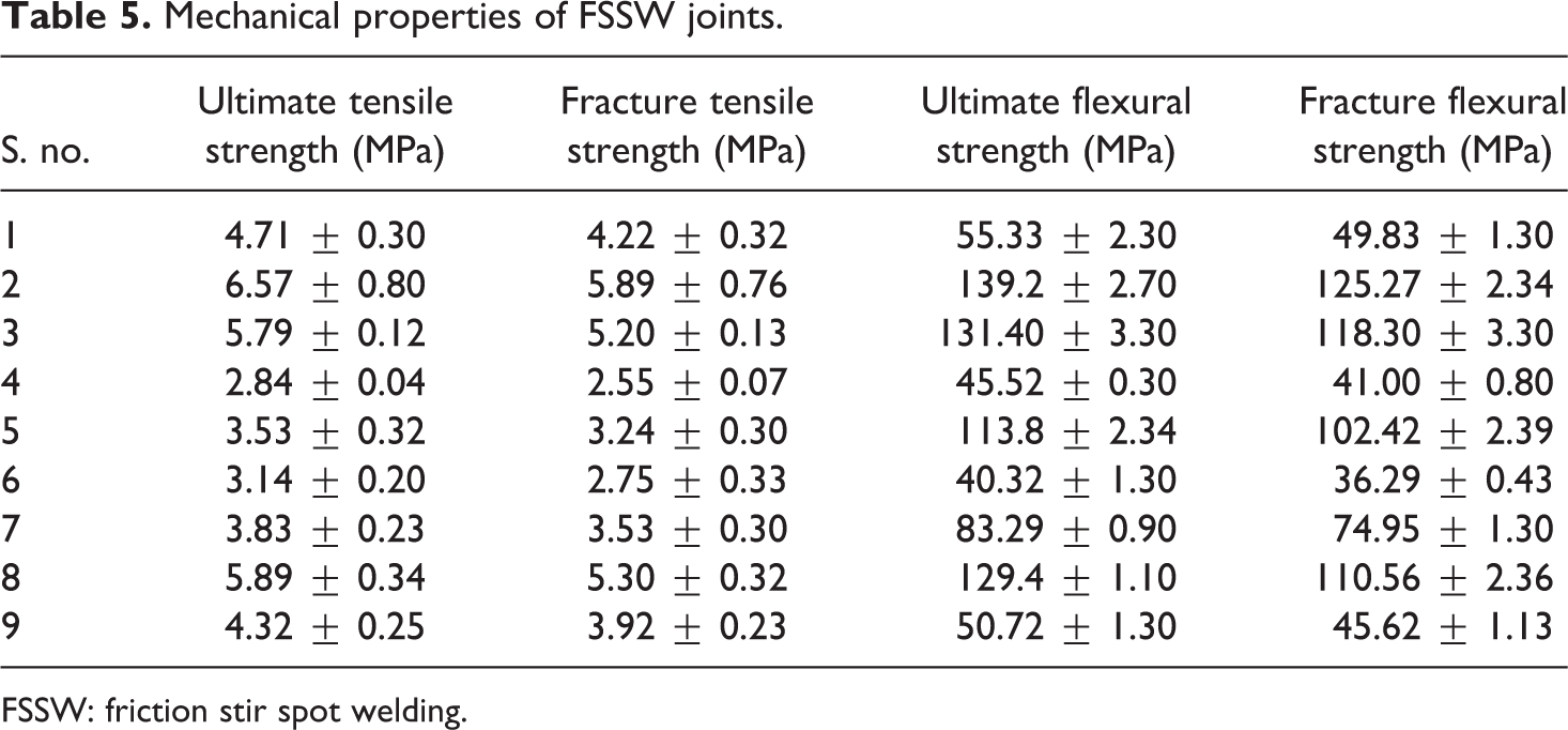
FSSW: friction stir spot welding.
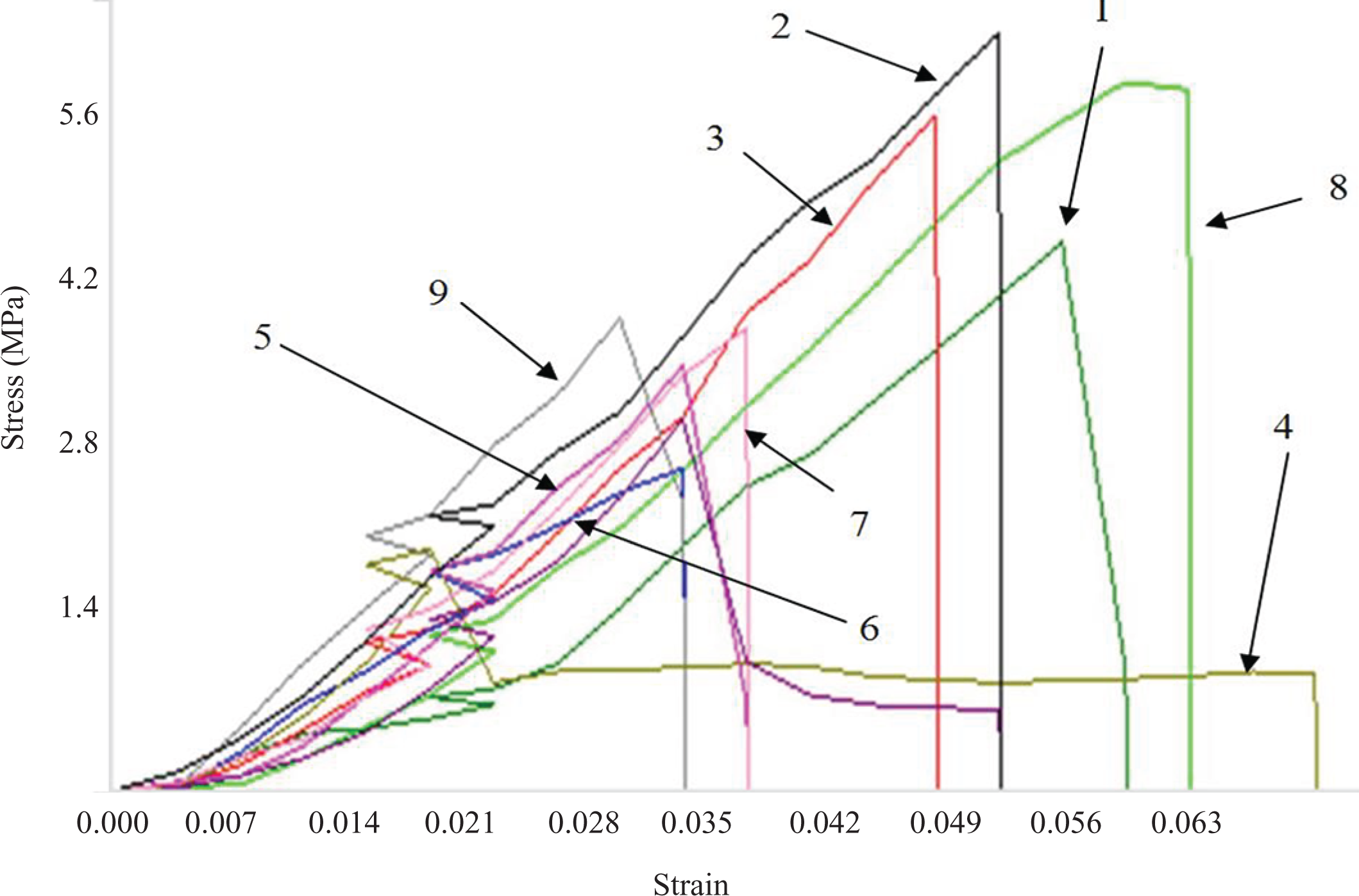
Stress versus strain curves of samples while tensile testing.
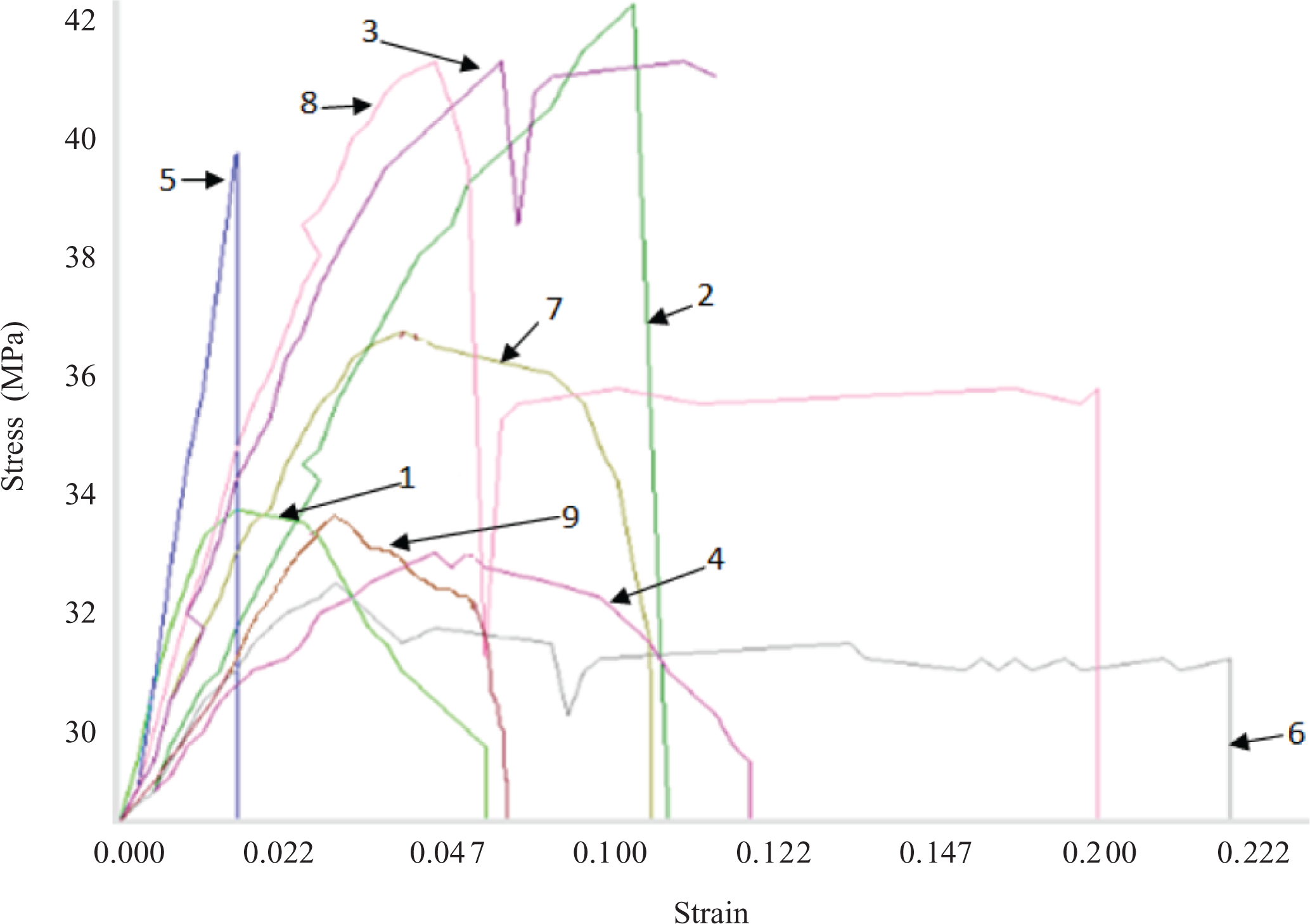
Stress versus strain curves of samples while flexural testing.
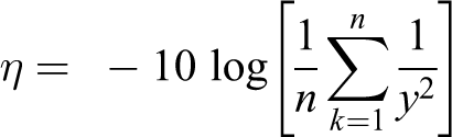
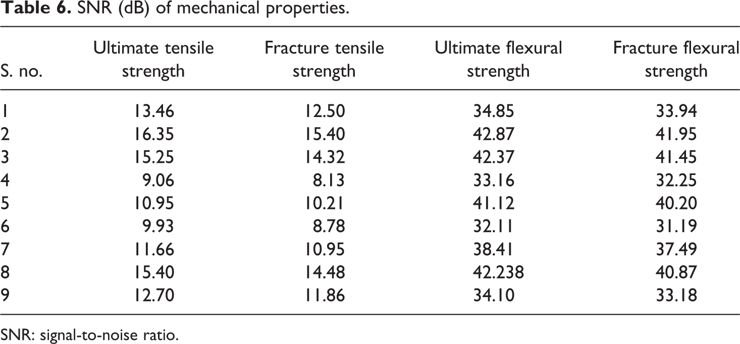
Based on Table 5, Table 6 shows signal-to-noise ratio (SNR) for larger the better type case by using following formula:
SNR (dB) of mechanical properties.
SNR: signal-to-noise ratio.
Where η is SNR, n is the no. of experiment, and y is the observed property at experiment no. k.
Based on Table 6, Figure 10 shows the main effect plot of SNR for ultimate (peak) tensile/flexural strength and fracture (break) tensile/flexural strength.
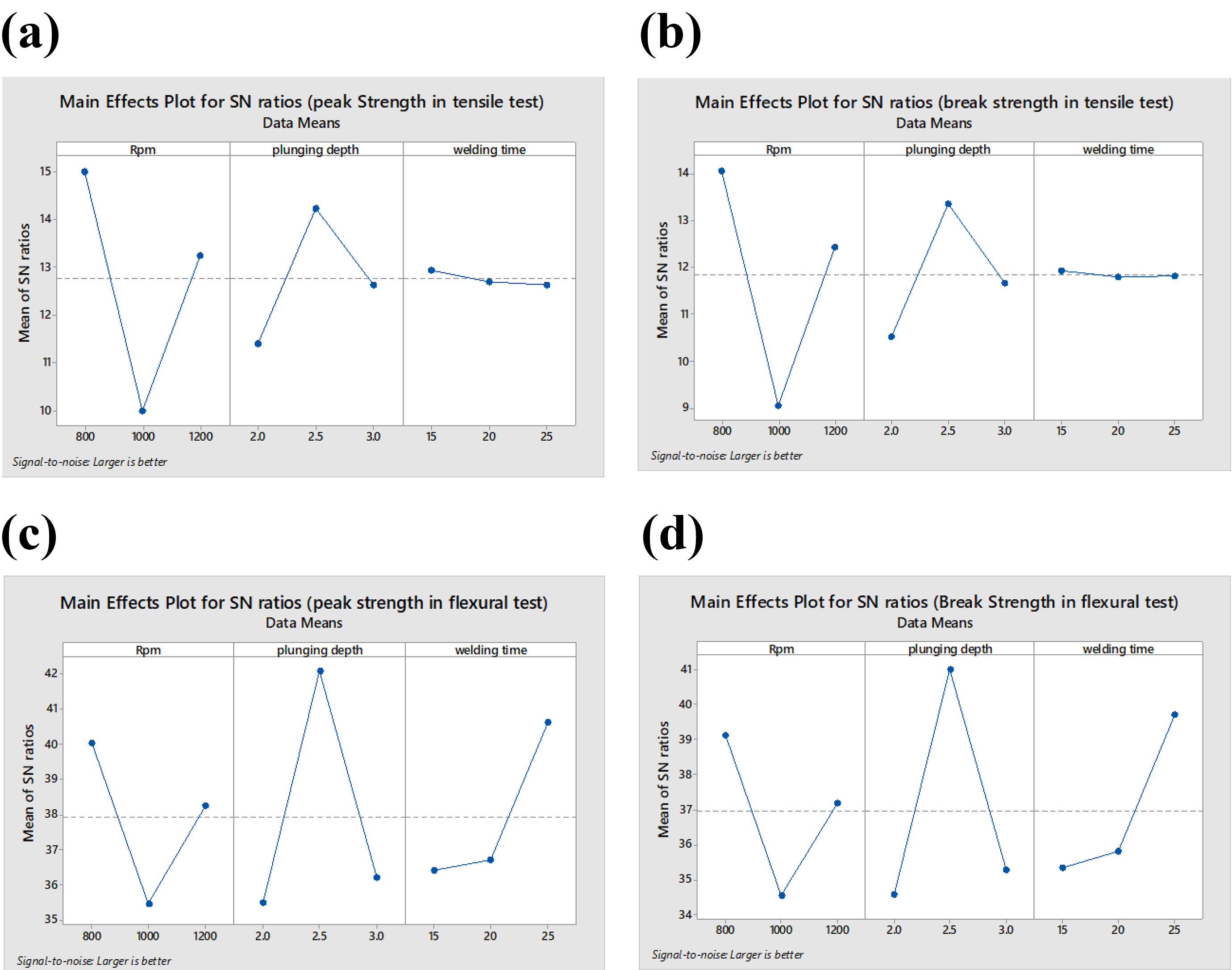
Main effect plot of SNR for (a) ultimate (peak) tensile strength, (b) fracture (break) tensile strength, (c) ultimate (peak) flexural strength, and (d) fracture (break) flexural strength.
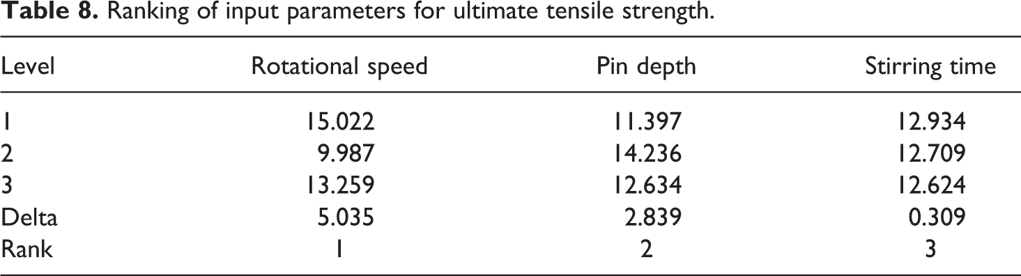
As observed from Figure 10, for obtaining maximum ultimate and fracture tensile strength of welded sample, it is suggested that the FSSW should be performed at 800 r/min with 2.5-mm pin depth for 10-s stirring time. Also, for getting maximum flexural strength (both ultimate and fracture), the best settings are 800 r/min with 2.5-mm pin depth for 25 s stirring/welding time. Further based on Table 6, analysis of variance and ranking table for ultimate tensile strength are presented in Tables 7 and 8, respectively.
Analysis of variance in SNRs for ultimate tensile strength.
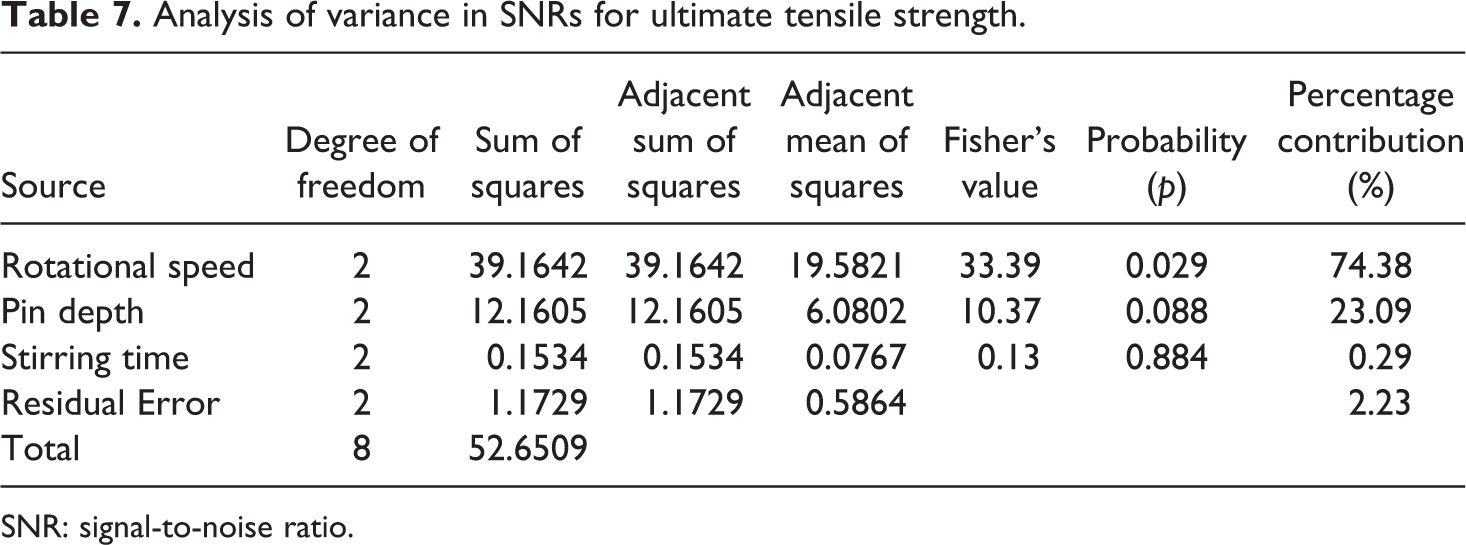
SNR: signal-to-noise ratio.
Ranking of input parameters for ultimate tensile strength.
As observed from Table 7, rotational speed is most contributing and significant factor at 95% confidence level (having p value less than 0.05). The other two parameters are not significant.
Prediction of ultimate tensile strength
For prediction of ultimate tensile strength, following mathematical formula has been used:

β
opt = optimum SNR value for peak strength
u = overall average of SN data
u
A1 = average of SN data for rotational speed at level 1
u
B2 = average of SN data for pin depth at level 2
u
C1 = average of SN data for stirring time at level 1
x
opt
2 = (10)
β
opt/10 (for properties when larger is better)
u = 12.76 dB
u
A1 = 15.022
u
B2 = 14.236
u
C1 = 12.934
β
opt = 12.76 + (15.022 – 12.76) + (14.236 – 12.76) + (12.934 – 12.76)
β
opt = 16.672 dB
x
opt2 = (10)
β
opt/10
x
opt2 = (10)16.672/10
x
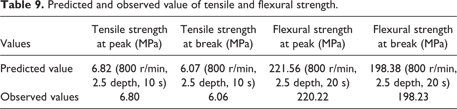
opt = 6.82 MPa Predicted value of optimum ultimate tensile strength = 6.82 MPa
On the suggested input parameters, setting the confirmatory FSSW process has been carried out and the observed value was 6.80 MPa. Similarly, predicted setting for all mechanical properties was deduced and confirmatory FSSW has been performed (see Table 9).
Predicted and observed value of tensile and flexural strength.
As observed from Table 5, experiment nos. 2 and 4 have maximum and minimum tensile strength. These samples were investigated on scanning electron microscope (SEM) at different magnifications on the fractured section (Figure 11).
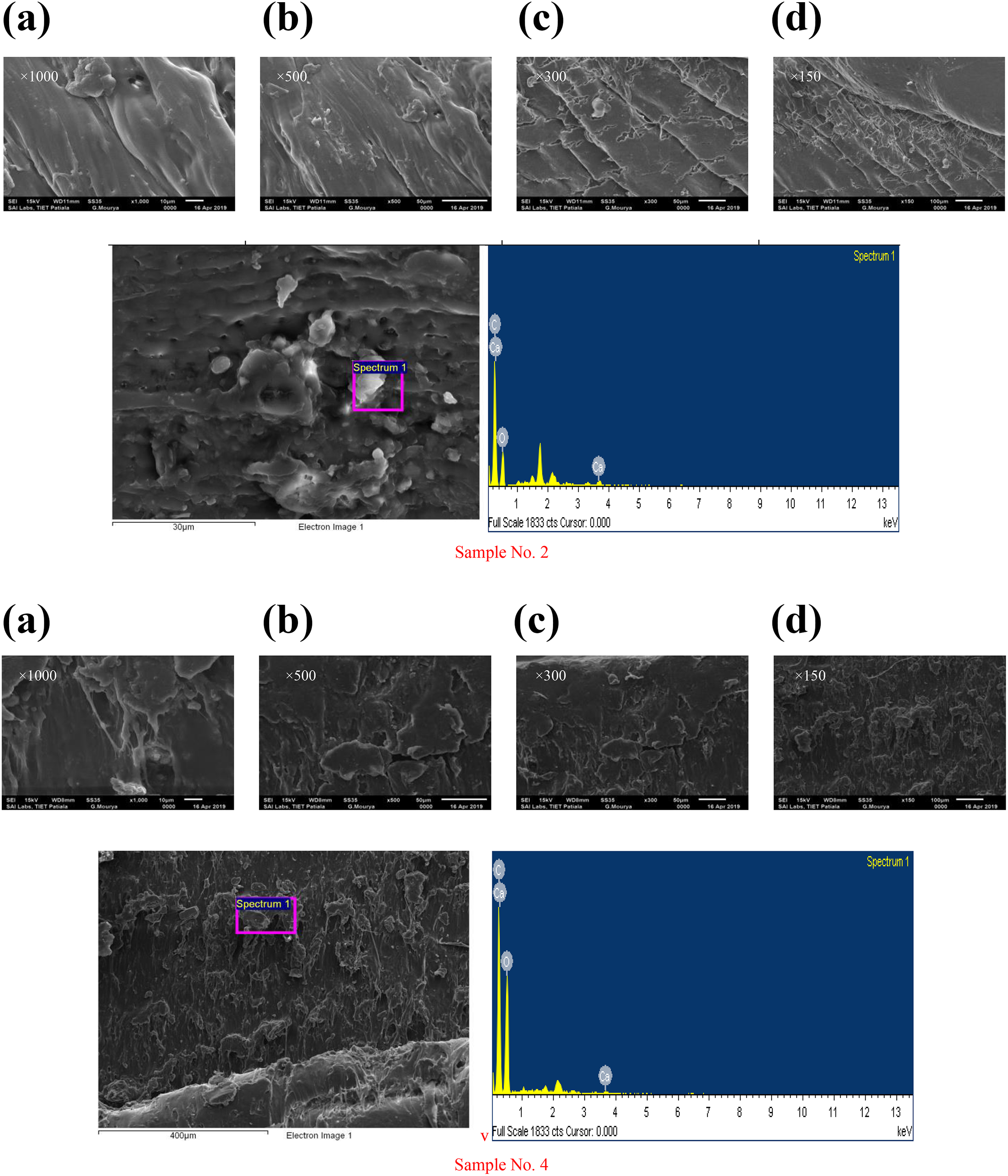
SEM and energy dispersive X-ray analysis (EDAX) for tensile samples 2 and 4 at fracture zone (as shown in Table 5).
As observed from Figure 11, both samples have shown the presence of HAp, PEKK, and CS in PLA matrix. Further, while comparing SEM for samples 2 and 4, it has been observed that fractured surface in sample 2 has shown failure mechanism similar to ploughing, whereas for sample 4, it is delamination. This may be one of the reasons for high porosity in sample 4 as compared to sample 2 (see Table 4) and better tensile properties for sample 2 as compared to sample 4 (see Table 5).
Further based on Table 6, Figure 12(a) to (c) shows contour plots of mean of SNR for FSSW process variables for combined optimization purpose (i.e. by considering tensile and fracture properties together). It is predicted by cross interacting the FSSW process that maximum value of SNR is predicted by maintaining 800 r/min rotational speed and 15 s stirring with 2.5-mm pin depth.
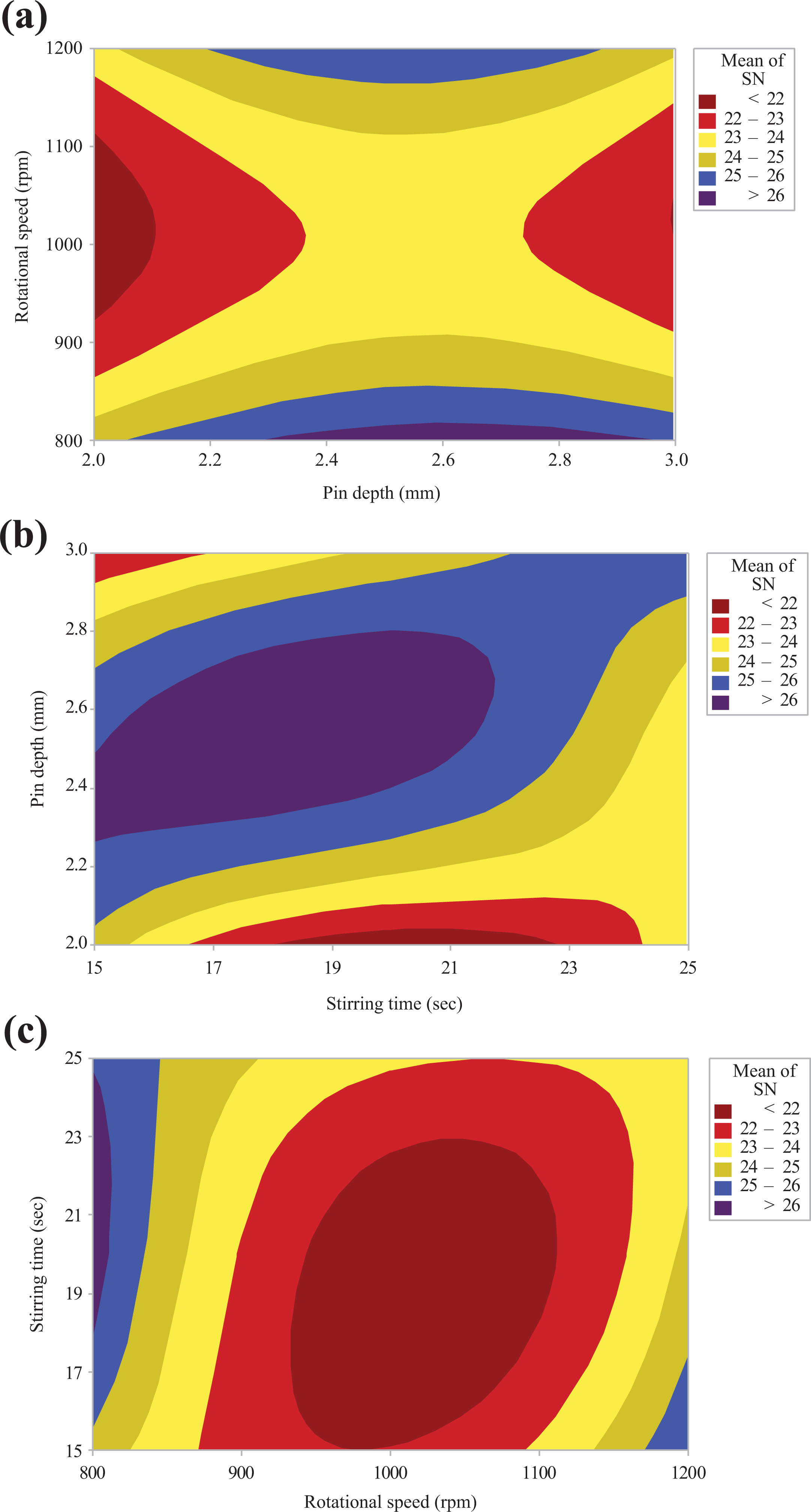
(a) Contour plot of mean of SNR versus rotational speed, pin depth, (b) contour plot of mean of SNR versus pin depth, stirring time, and (c) contour plot of mean of SNR versus stirring time, rotational speed.
DSC analysis
Figure 13 shows differential scanning calrorimetry (DSC) results of sample no. 2 (with maximum mechanical properties) and virgin PLA. The interpretation of peak melting point made by DSC analysis shows that there is a minor variation in melting point of virgin PLA and sample 2 (153.28°C for sample no. 2 and 154.51°C for virgin PLA). Similarly, the integral heat energy of sample no. 2 was −22.68 J/g, whereas −21.51 J/g was for virgin sample. The differences in the integral heat energy may be due to the presence of 5% PEKK-HAp-CS content and optimum processing conditions in sample 2, which have made it more thermally stable material as compared to virgin PLA.
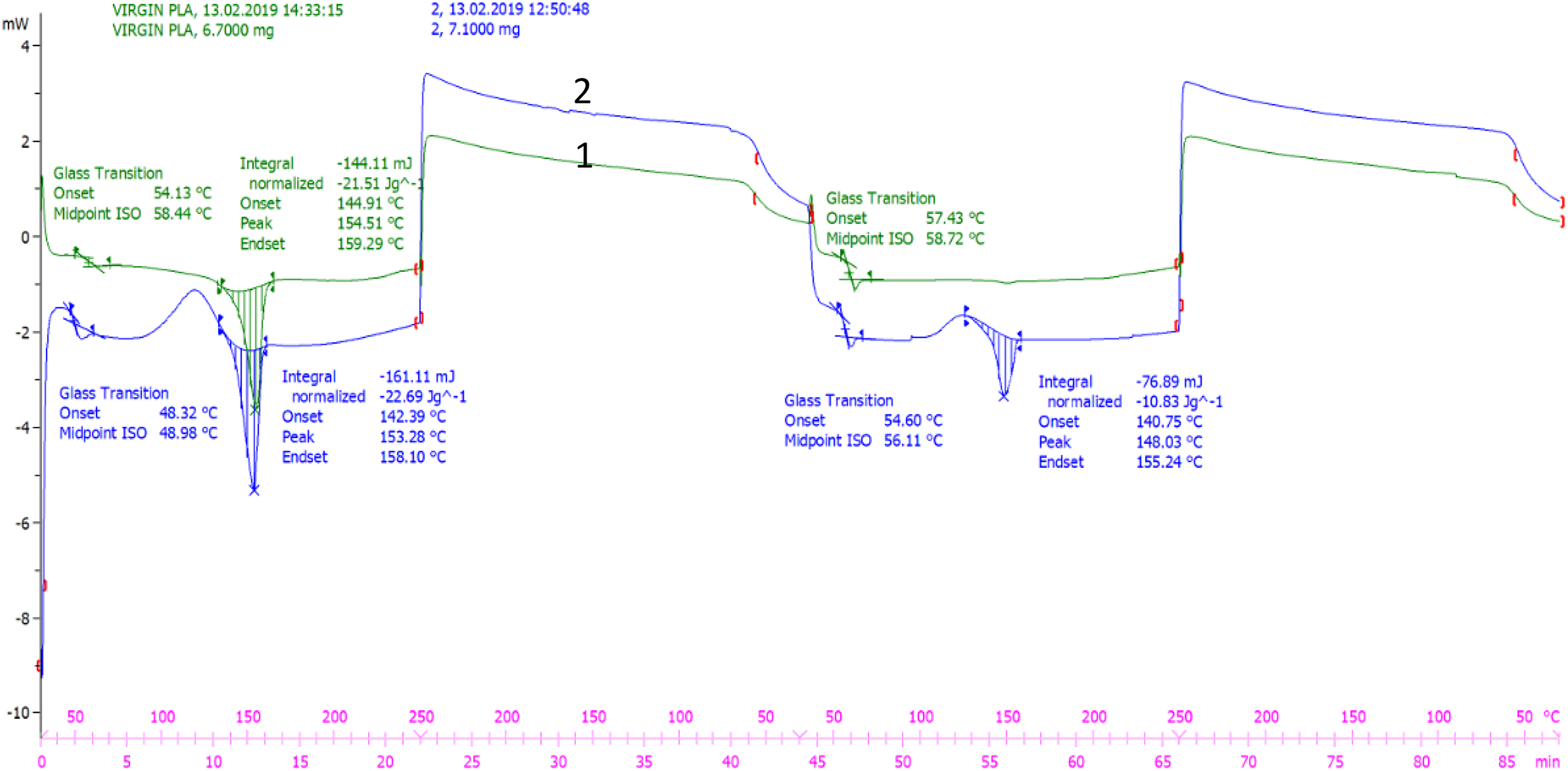
DSC graph for sample 2 and virgin PLA.
Conclusions
Based on the preliminary experimentations, it has been observed that of three compositions/proportions of PEKK-HAp-CS, 94% PEKK-4% HAp-2% CS attained maximum tensile properties, so this composition was finalized for further extrusion. Finally, based on extrusion results, 95% PLA-5% (94% PEKK-4% HAp-2% CS) has been selected for compression molding and finally for FSSW of bone scaffolds. Following conclusions have been made from the present study: The FSSW with consumable tool has been successfully performed as a novel process for PLA composite. The results of the study suggest that FSSW of 95% PLA-5% (94% PEKK-4% HAp-2% CS) composite is feasible for small repairs especially for biomedical scaffolds with acceptable/controlled tensile, flexural, morphological, and thermal properties. It has been observed that the joints prepared by FSSW have some porosity, which may be poor from mechanical strength viewpoint but are acceptable for biomedical applications as this will support the growth of cells. With regard to the best parametric settings in the present case study, maximum tensile and flexural strength were obtained for sample no. 2 (parametric combination: 800 r/min, 2.5-mm pin depth, and 15 s stirring time). These settings have been counter verified based on confirmatory experiments with 95% confidence level.
For this study, the joints prepared were not subjected to in vitro and in vivo analyses. The same should be explored before applying these joints in biomedical applications.
Footnotes
Acknowledgement
The authors are thankful to SERB for financial support.
Funding
The author(s) disclosed receipt of the following financial support for the research, authorship, and/or publication of this article: This work was financially supported by SERB (file no. IMRC/AISTDF/R&D/P-10/2017).