
Abstract
In this article, the elastic buckling response of rectangular simply supported and clamped fiber-metal laminates (FMLs) subjected to uniaxial compressive loading is investigated using the finite element method and eigenvalue buckling analysis. Using validated finite element method (FEM) models, the buckling coefficient-aspect ratio diagrams and the mode shapes of nine GLARE grades are obtained and studied along with the diagrams and the mode shapes of three unidirectional glass-epoxy composites and monolithic 2024-T3 aluminum. It is found that the critical average buckling stress and the buckling load of the materials increases for increasing metal volume fraction, when the plate aspect ratio is greater than 1.5. The rule of mixtures is evaluated and found to be a simple method to estimate approximately the average critical buckling stress of the GLARE plates. An approximate formula is derived for the estimation of the critical buckling coefficient of the GLARE plates using the buckling coefficients of their constituents. The applicability of the results to thermoplastic-based FMLs is discussed.
Keywords
Introduction
Fiber-metal laminates (FMLs) are hybrid composite materials, consisting of alternating metal layers bonded to fiber-reinforced prepreg layers. ARALL (Aramid-Reinforced ALuminum Laminates), CARALL (Carbon-Reinforced ALuminum Laminates), and GLARE (GLAss REinforced) belong to this new family of materials. GLARE is the most successful FML up to now and is currently being used for the construction of primary aerospace structures, such as the fuselage of the Airbus A380 air plane. Further applications have also been considered: aircraft cargo floors of Boeing 777, aircraft engine cowlings, bonded GLARE patch repair, aircraft stiffeners with a wide variety of shapes, cargo containers, and seamless GLARE tubes. 1 –4 The assessment of the mechanical performance of FMLs is an intensive field of scientific research. 1 –21 This research includes thermoplastic-based FMLs. 15 –17,19 In the study of Mugica et al., 15 the impact response of FMLs with self-reinforced polypropylene composite layers is investigated. This composite was selected since it combines the versatility and recyclability of a 100% thermoplastic polymer with the high performance of a fiber-reinforced composite which includes exceptional impact resistance. In the study of McKown et al., 16 the scaling effects of FMLs consisting of self-reinforced thermoplastic composite layers based on polypropylene fibers and polypropylene matrix are analyzed as far as their tensile, flexural, and low-velocity impact response is concerned. In the work of Cortes and Cantwell, 17 the low- and high-velocity impact properties of FMLs based on carbon fiber-reinforced poly-ether-ether-ketone (PEEK) and glass fiber-reinforced poly-ether-imide (PEI) composites are investigated experimentally. These FMLs which are based on high-temperature thermoplastic composite materials have been selected because they represent an attractive option for the construction of supersonic transportation aircrafts.
Local buckling is a very important issue for the design of stiffened thin-walled structures. Due to the high static strength of FMLs and their high fatigue and damage tolerance resistance, thin-walled FML structures are being constructed primarily for aerospace applications. The buckling behavior of these structures is of great interest for aerospace engineers. Recently, various scientific articles concerning the buckling strength of composite laminates and FMLs have been published. 5,6,8,9,14,22,23 In these articles, the buckling and post-buckling response of plates and columns with various profiles consisting of FMLs is analyzed.
This article deals with the elastic buckling of rectangular FML plates under uniaxial compression. The elastic buckling of thin plates is a classical problem of the strength of materials, which has great practical importance. Plate buckling must always be considered during the design of many engineering applications where stiffened thin-walled structures are employed. For the purpose of buckling analysis, the wall plates among stiffeners could be analyzed approximately as isolated rectangular plates. Since FMLs are mainly used for the construction of stiffened thin-walled aerospace structures, the buckling strength of FML plates is very important. In the study of Rengui et al., 5 an elastoplastic buckling and post-buckling analysis of FMLs subjected to in-plane compressive loading is implemented using the finite difference method. Results concerning the critical buckling load and post-buckling response of a specific FML grade are presented there. In the studies of Mania and York and Banat et al., 6,14 the buckling and post-buckling response of FML columns with open cross-section under axial compression is investigated using semi-analytical, analytical, and finite element methods. The effect of thin-ply material technology on the response of the columns is evaluated in the work of Mania and York. 6 In the studies of Al-Azzawi et al., 8,9 the buckling and post-buckling behavior of FMLs with doublers and splices is investigated.
The principal objective of this article is to predict the elastic buckling coefficient of simply supported and clamped plates consisting of different FMLs under uniaxial compression and provide pertinent diagrams of the buckling coefficient versus the plate aspect ratio. ANSYS FEM analysis software is employed for this purpose. 24 An approximation formula to predict the buckling coefficients of FMLs is derived using the rule of mixtures for the buckling stresses. The corresponding mode shapes are also predicted numerically and studied. The effect of different support type and of various structural parameters on the buckling response of the plates are also studied.
Problem definition
We consider a thin simply supported or clamped rectangular FML plate with length α along the loading direction, width b, and thickness t. The plate consists of alternating layers of aluminum and unidirectional (UD) glass-epoxy. The plate is loaded statically with a uniaxial constant compressive stress σx along one of the edges, as shown in Figure 1. Since the opposite parallel edge of the plate is not allowed to move along the loading x-direction, the plate will buckle for a specific critical value of the applied stress σx . The elastic buckling of the plate is considered in this article.
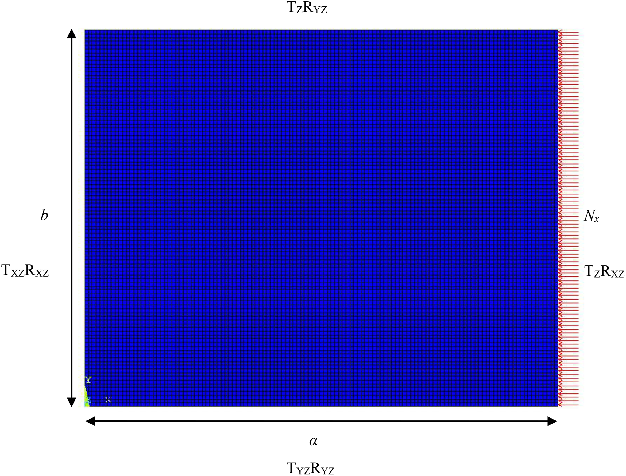
Top view of the finite element mesh of a rectangular 250 × 200 mm plate (α/b = 1.25) along with the applied compressive loading and simply supported bc.
The critical buckling load Nx , corresponding to the critical buckling stress σx , will be calculated numerically using FEM analysis with ANSYS software. The classical eigenvalue buckling analysis is employed for this purpose. The corresponding mode shape will also be determined numerically. Then, the buckling coefficient k will be calculated. Using variable plate dimensions, the (k, α/b) curves of plates consisting of different material systems will be obtained. The effect of the different boundary conditions (bc), the orientation of the glass fibers, and the metal volume fraction (MVF) on the buckling response of the FMLs is analyzed. A comparison with the buckling response of traditional UD glass-epoxy composite laminates and monolithic aluminum plates is also implemented.
Finite element modeling procedure
Since the plates are thin, we use SHELL181 elements 24 for their modeling with plane geometry. These quadrilateral elements have four nodes with three translational and three rotational degrees of freedom per node. SHELL181 elements are suitable for analyzing thin to moderately thick layered shell structures. The orientation of glass fibers and the definition of material properties of each layer in the FMLs and in the composite laminates is implemented using the ANSYS section data command.
In our analysis, the FML consists of perfectly bonded laminae. The bonds are presumed to be infinitesimally thin as well as non-shear deformable. This is a classical assumption for the buckling analysis of laminated composite materials, 25,26 which is implemented by using SHELL181 elements in our FEM models. Consequently, we do not consider any debonding between aluminum and glass-epoxy layers of the FMLs. In the high-velocity ballistic impact experiments of Hoo Fatt et al., 21 the GLARE 5 targets, which consisted of 2024-T3 aluminum and S2 glass-epoxy layers, have been examined after the severe impact damage which resulted in their full perforation by the cylindrical free-flying hard projectiles. It was found that there was no evidence of debonding between the glass-epoxy and aluminum layers. It is noted that those GLARE 5 specimens experienced very high, sudden, approximately concentrated normal impact loads, about 26 kN in some cases according to the calculations of Hoo Fatt et al. 21 Since under these extreme impact damage conditions there was not any debonding between aluminum and glass-epoxy layers, our corresponding consideration used for the buckling analysis of the GLARE plates is realistic.
The metal layers of the FMLs and the monolithic aluminum plates consist of 2024-T3 aluminum alloy, which is modeled using an isotropic linear elastic material model. We idealize the material behavior of the UD glass-epoxy layers with an orthotropic linear elastic material model. In order to simulate the uniaxial compressive stress σx , a line pressure load Nx is applied along one edge of each plate whereas the opposite parallel edge is not allowed to move along the x-direction. The magnitude of Nx is always equal to unity.
For the prediction of the critical buckling load and the corresponding mode shape of each plate, we implement an eigenvalue buckling analysis. Since the applied load is equal to unity, the lowest eigenvalue yields the predicted critical value of Nx . In order to verify the convergence of FEM results, the magnitude of the buckling load Nx along with the corresponding mode shape, we built a fine and a very fine mesh model with increasing plate mesh density for each specific plate we analyze. A very fine mesh model corresponding to a GLARE FML is depicted in Figure 1. For the fine and the very fine mesh model of each plate, we calculate the critical value of Nx , we plot the critical mode shape, and compare them in order to verify that satisfactory convergence has been achieved.
In order to ensure that elastic buckling occurs, the stress levels of the plies corresponding to the critical buckling load of the plate are always checked. In aluminum layers, the equivalent von Mises stresses are always well below the yield point. In prepreg layers, the maximum stress failure criterion is employed in order to verify that the stress levels are always well below the limits.
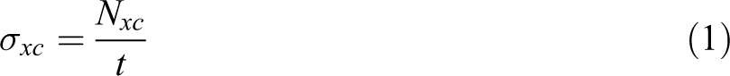
The average critical buckling stress is obtained for each critical value of the loading Nxc as follows
The buckling coefficient of the laminates is calculated with the formula 27
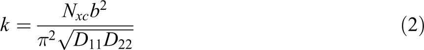
where Dii (i = 1, 2) are the bending stiffnesses of each laminate. 25
The buckling coefficient of the monolithic aluminum plates is calculated with the relation 28 –30
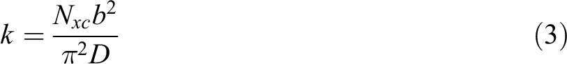
where D is the bending stiffness of the plate.
For each specific material we analyze, in order to obtain the (k, α/b) and the (σxc , α/b) curves, different FEM models are built with variable aspect ratio. The dimension b is always equal to 0.2 m whereas the dimension α varies so that the aspect ratio satisfies the following inequalities: 0.5 ≤ α/b ≤ 5. The total thickness t of all plates is always equal to 1.875 mm. When α/b = 1, the fine mesh models consist of 2,500 square elements and the very fine mesh models consist of 10,000 square elements. It is noted that the buckling coefficient does not depend on the values of b and t, but it depends on the aspect ratio a/b.
We apply the presented finite element modeling procedure to the following GLARE grades: GLARE 2A-3/2-0.458, [Al/0° gl/0° gl/Al/0° gl/0° gl/Al] GLARE 2B-3/2-0.458, [Al/90° gl/90° gl/Al/90° gl/90° gl/Al] GLARE 2A-4/3-0.281, [Al/0° gl/0° gl/Al/0° gl/0° gl/Al/0° gl/0° gl/Al] GLARE 2B-4/3-0.281, [Al/90° gl/90° gl/Al/90° gl/90° gl/Al/90° gl/90° gl/Al] GLARE 4/3-0.281, [Al/45° gl/45° gl/Al/45° gl/45° gl/Al/45° gl/45° gl/Al] GLARE 5-3/2-0.292, [Al/0° gl/90° gl/90° gl/0° gl/Al/0° gl/90° gl/90° gl/0° gl/Al] GLARE 3/2-0.292, [Al/0° gl/0° gl/0° gl/0° gl/Al/0° gl/0° gl/0° gl/0° gl/Al] GLARE 3/2-0.292, [Al/90° gl/90° gl/90° gl/90° gl/Al/90° gl/90° gl/90° gl/90° gl/Al] GLARE 3/2-0.292, [Al/45° gl/45° gl/45° gl/45° gl/Al/45° gl/45° gl/45° gl/45° gl/Al]
We also apply the same FEM procedure to the following symmetric UD glass-epoxy composite laminates: [0°]15, [90°]15, [0°/90°/0°/90°/0°/90°/0°/
The 0° fiber orientation angle is always parallel to the loading direction. The FEM procedure is also applied to monolithic 2024-T3 aluminum plates. The thickness of aluminum layers in the GLARE laminates is denoted in millimeter by the last number of their aforementioned coded name. Each prepreg ply of the examined GLARE and composite laminates has a thickness of 0.125 mm and consists of S2-glass UD fiber prepregs. The material properties of aluminum and prepreg layers considered for our calculations can be found in the work of Yaghoubi and Liaw. 12 The elastic material properties used for the glass-epoxy layers are given in Table 1. A total of 452 finite element models with very fine mesh have been implemented, solved and studied in order to derive the (k, α/b) curves presented in this article and analyze the critical mode shapes.
Elastic material properties of S2 glass fiber-reinforced epoxy layers.
It is noted that the described finite element modeling procedure can be applied to other fiber-metal laminated material systems consisting of metal layers and thermoplastic fiber-reinforced composite layers, such as carbon fiber-reinforced PEEK composites and glass fiber-reinforced PEI composites. The material properties of the FEM models must be updated accordingly.
Validation of FEM models
The application of suitable bc is a critical step for a buckling analysis, since the buckling load is very sensitive as far as the influence of different bc is concerned. The simply supported bc along the edges of the plates have been applied as shown in Figure 1. For example, the symbols TZRXZ of the edge of the plate where Nx is applied, mean zero nodal z-axis translation and zero nodal x-axis and z-axis rotations. The clamping of the plates has been achieved by imposing zero transverse rotation along their edges in addition to the aforementioned bc of simple support. In order to validate our FEM procedure and the suitability of the applied bc, we have initially compared the FEM results with corresponding theoretical results for monolithic aluminum plates.
The buckling coefficient of a simply supported plate consisting of isotropic material can be calculated using the following expression 28 –31
where m is the number of half-waves of the buckled shape in the loading direction.
To the authors’ knowledge, there is not an exact finite analytical expression concerning the solution of the problem of elastic buckling of a clamped rectangular plate under uniaxial compression, even when the plate is isotropic. 29 However, the buckling coefficient of a clamped plate consisting of isotropic material can be calculated using the following approximate formulas 28


Values of k corresponding to specific aspect ratios of clamped plates can be found in the literature. 29,30 In Figure 2, the numerical (k, α/b) curves of aluminum plates are compared with corresponding theoretical curves calculated using equations (4) to (7) and k values from the literature. 28 –30 A very close agreement between our FEM results and the values from the literature can be observed from Figure 2. Furthermore, the FEM calculated nodal lines (with zero deflection) of the critical mode shapes corresponding to plates with sufficient length α are perpendicular to the loading direction, as also predicted from theoretical models. 28 –30 Additionally, the number of half-waves of each FEM calculated critical mode shape is equal to the corresponding number of half-waves calculated using the analytical formula of Hughes and Paik 28 in the case of simply supported bc. These facts demonstrate the validity of the implemented finite element modeling procedure as far as the monolithic aluminum plates are concerned. Furthermore, they demonstrate the suitability of the bc applied to our FEM models. The same bc are used for the considered clamped and simply supported composite plates and FMLs as well.
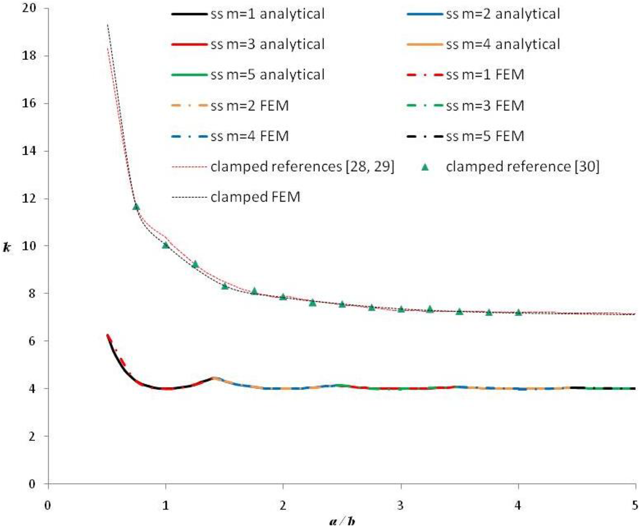
FEM values versus literature values of buckling coefficients of simply supported (ss) and clamped aluminum plates under uniaxial compression.
In order to validate our finite element models of the examined GLARE and composite laminates, we compare the FEM results with corresponding analytical results for specially orthotropic laminated plates. The critical buckling load of simply supported laminated plates consisting of specially orthotropic layers can be calculated using the following equation 25

where Dij are the bending stiffnesses of each laminate.
The buckling coefficient corresponding to the buckling load predicted using equation (8) is obtained from equation (2). In Figure 3, the numerical (k, α/b) curves of the analyzed [90°]15 UD composite laminates are compared with corresponding analytical curves calculated using equations (8) and (2). A very close agreement between the FEM results and the analytical results can be observed from Figure 3. The FEM calculated nodal lines of the critical mode shapes corresponding to simply supported laminates with sufficient length α are again perpendicular to the loading direction, as also predicted from theory. 25 The number of half-waves of each FEM calculated critical mode shape is equal to the corresponding number derived graphically using the analytical (k, α/b) curves in the case of simply supported bc. We have verified that corresponding numerical and analytical results are in close agreement in the remaining two examined cases of UD composite laminates as well. These facts demonstrate the validity of the implemented finite element modeling procedure as far as the simply supported UD composite laminates are concerned. Since the same models are used for the clamped UD composite laminates, with the modified and validated bc as discussed previously in this article, it is concluded that the implemented FEM modeling procedure is validated for the clamped UD composite laminates as well.
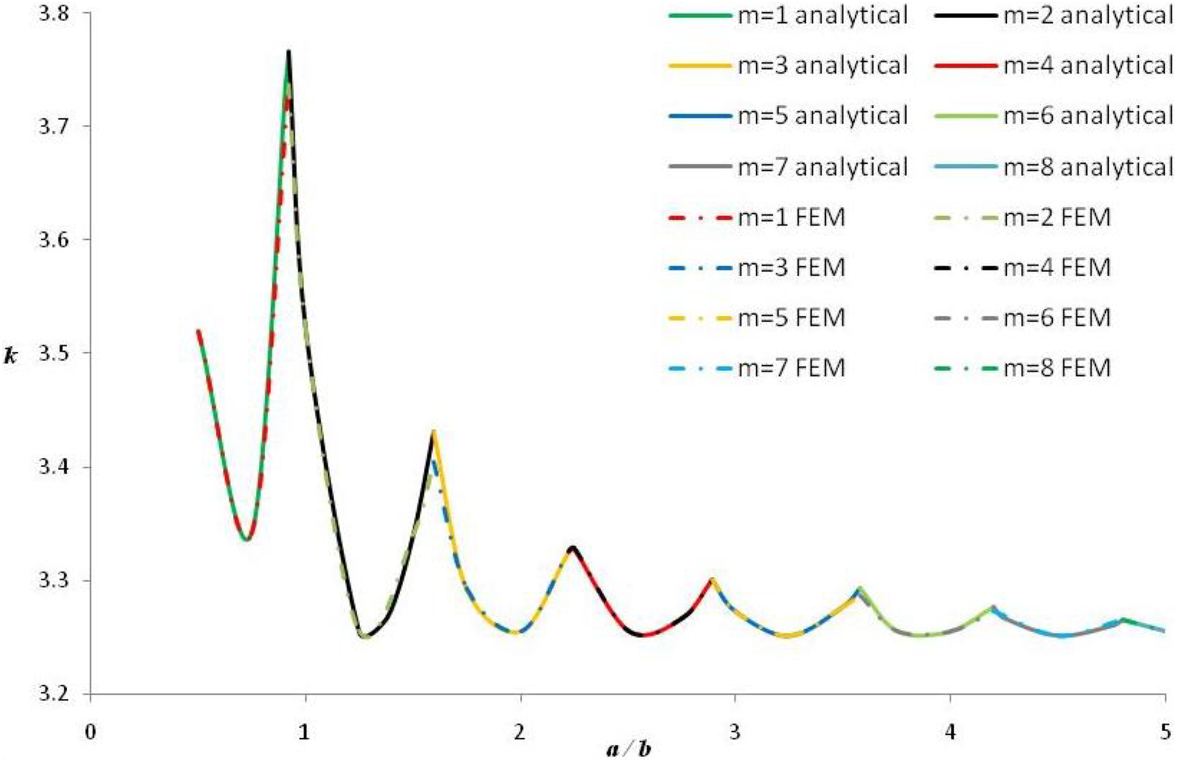
FEM values versus analytical values of buckling coefficients of simply supported UD glass-epoxy composite [90°]15 laminates under uniaxial compression.
The same reasoning is followed for the validation of the FEM models corresponding to each of the examined GLARE plates with specially orthotropic prepreg layers. In Figure 4, the numerical (k, α/b) curves of GLARE 2A-4/3-0.281 FMLs are compared with corresponding analytical curves calculated using equations (8) and (2). A very close agreement between the FEM results and the analytical results is found in Figure 4. We have verified that numerical and analytical (k, α/b) curves are in close agreement in the remaining examined cases of GLARE plates with specially orthotropic prepreg layers as well. As in the case of the UD composite laminates, the direction of the nodal lines of the critical mode shapes and the number of their half-waves always agree with theory. 25 Consequently, following the same reasoning described previously for the UD composite laminates, the FEM models of these GLARE plates are validated for simply supported and clamped bc.
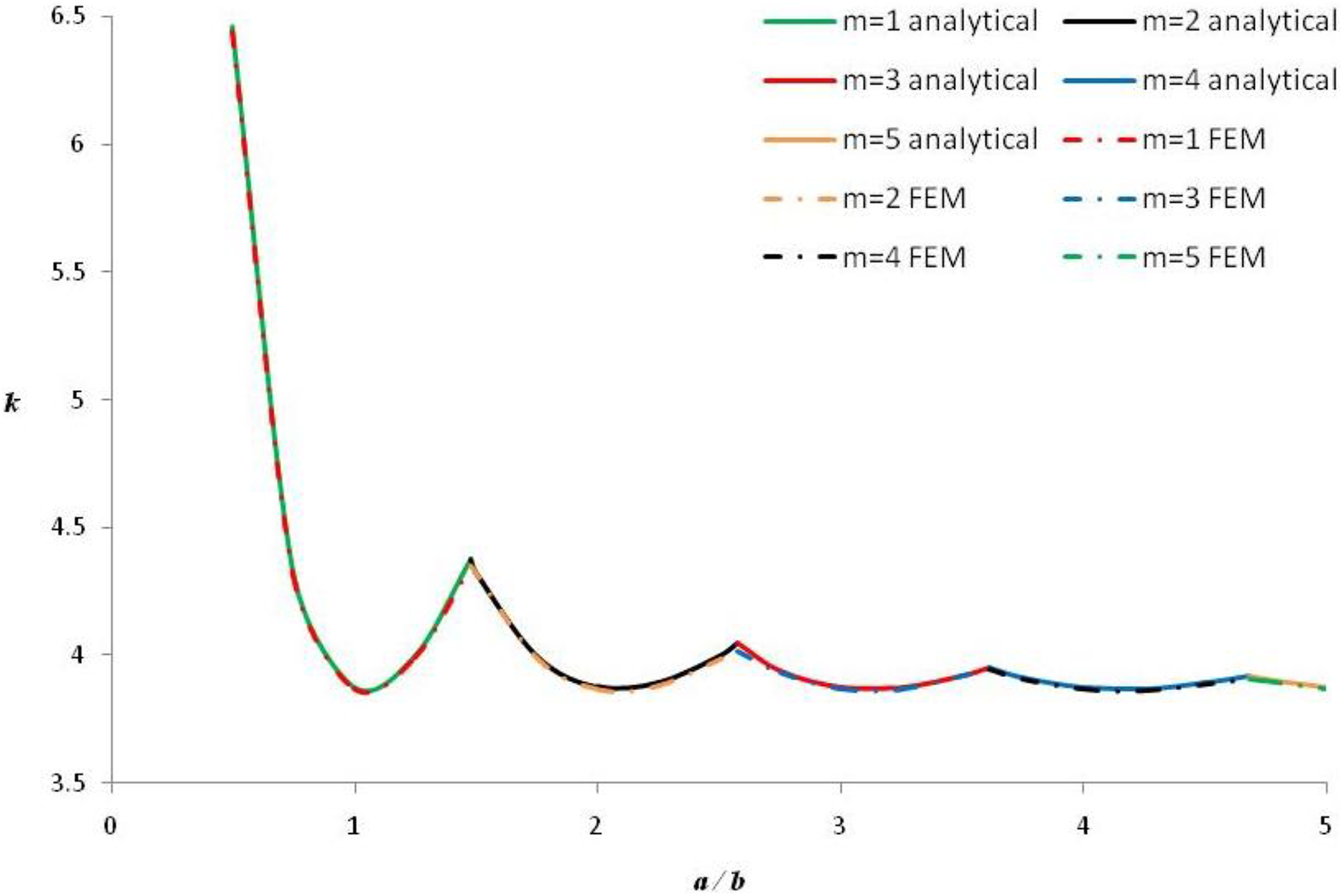
FEM values versus analytical values of buckling coefficients of simply supported GLARE 2A-4/3-0.281 plates under uniaxial compression.
Results and discussion
In Figures 5 and 6, the calculated diagrams of buckling coefficients corresponding to the analyzed plates are given for simply supported and clamped bc, respectively. Such diagrams of buckling coefficients are valuable for the assessment of the buckling strength of plates since the buckling load and stress can be directly obtained using the diagrams in combination with equations (1) and (2), for a specific aspect ratio.
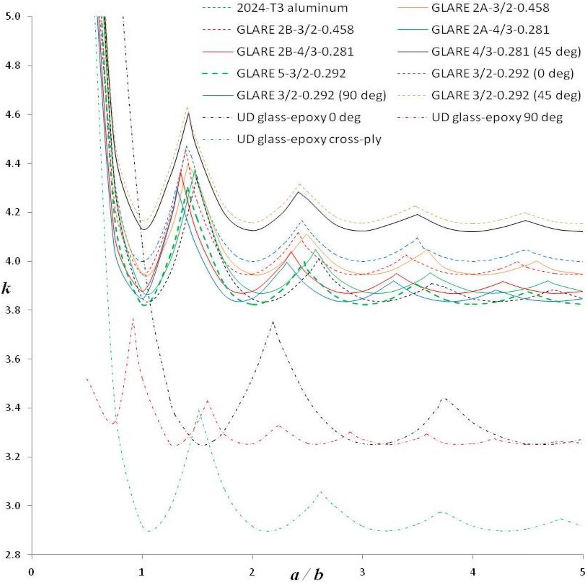
Buckling coefficients of simply supported GLARE, aluminum, and UD composite plates under uniaxial compression.
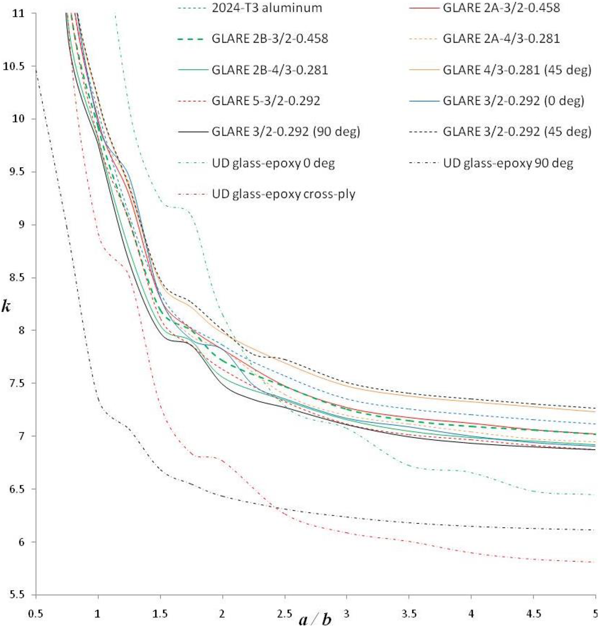
Buckling coefficients of clamped GLARE, aluminum, and UD composite plates under uniaxial compression.
It can be observed from Figure 5 that the considered simply supported GLARE plates demonstrate (k, α/b) curves which follow the trend of the monolithic aluminum (k, α/b) curve closer than the trend of the glass-epoxy (k, α/b) curves. This observation means that aluminum governs the buckling response of these GLARE plates, regardless of the fact that the MVF is less than 0.5 for the GLARE panels with 0.292 mm thick aluminum layers. It can also be observed from Figure 5 that the orientation of the fibers has a very strong effect on the behavior of the (k, α/b) curves in the case of UD composite laminates, whereas this effect of the fiber orientation angle is small in the case of the GLARE plates.
With reference to the (k, α/b) curves of the clamped plates depicted in Figure 6, it can be seen that the orientation of the fibers has again a strong effect on their behavior in the case of the UD composite laminates, but this effect now alters their behavior for several GLARE plates as well. For example, the variations of the (k, α/b) curves of the three GLARE 3/2-0.292 grades do not appear in the (k, α/b) curve of monolithic aluminum plates. It is shown from Figures 5 and 6 that the clamped bc result in greater k values in comparison with the simply supported bc for all of the 13 examined materials. It is also demonstrated from these figures that the variations of the (k, α/b) curves of the considered materials are small when α/b becomes greater than 4.
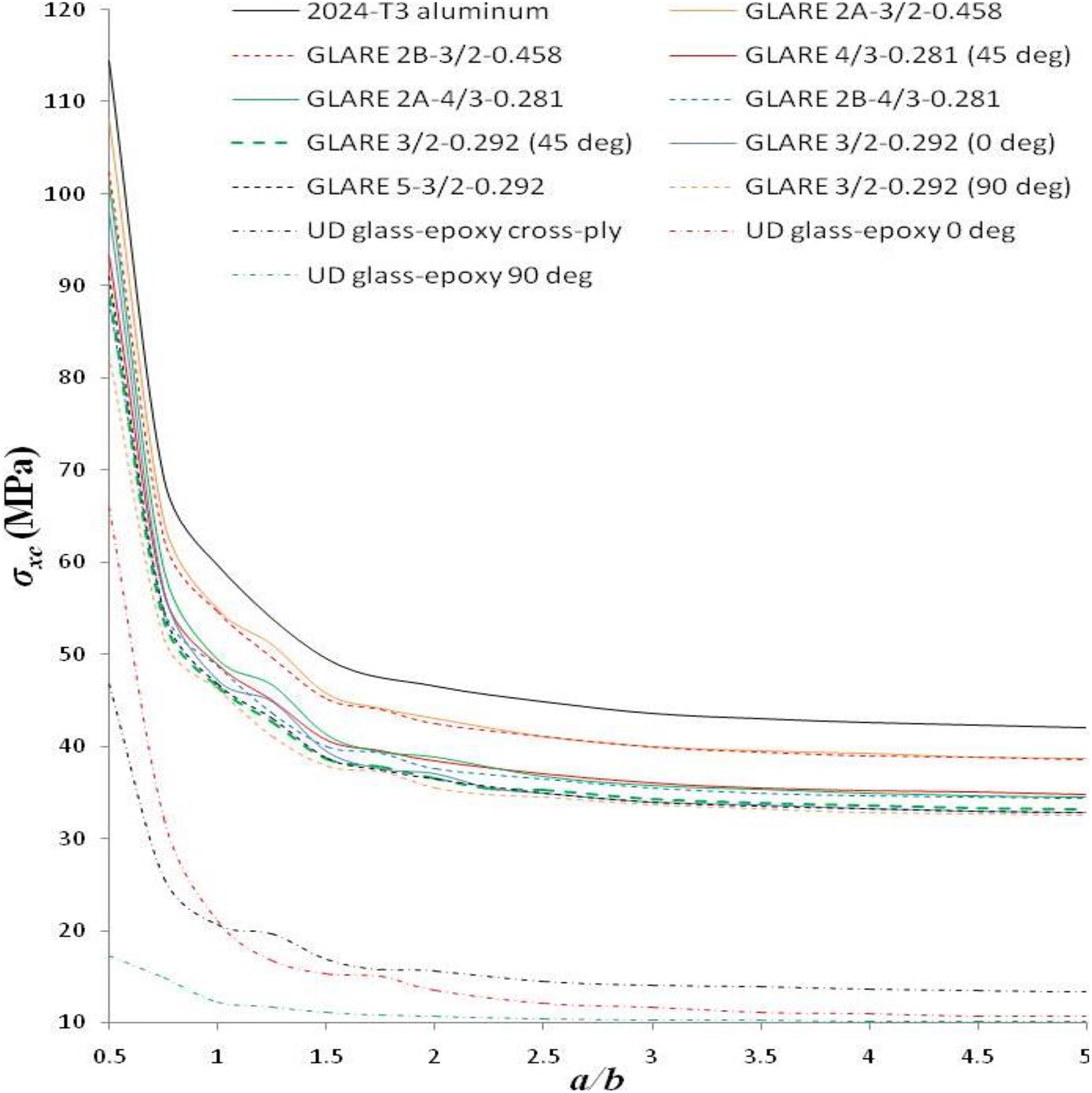
It is not convenient to compare the buckling strength of the considered materials using the values of their buckling coefficients. The average critical buckling stress offers a direct measure of the plates’ buckling strength. For this reason, in Figures 7 and 8, the (σxc , α/b) diagrams of all plates are depicted for simply supported and clamped bc, respectively. From Figures 7 and 8, it is observed that aluminum offers the highest critical values of σxc and Nxc since all plates have equal thickness. The UD composites have the lowest critical values of σxc and Nxc . The GLARE plates offer intermediate critical σxc and Nxc values. By setting the GLARE plates in the order corresponding to their descending σxc and Nxc values, it is found that when α/b >1.5, the critical values of σxc and Nxc increase as the MVF of the 13 materials increases for both types of bc. In the case of simply supported GLARE plates, a 45° fiber orientation angle increases the initial critical σxc and Nxc values of the GLARE 2A-4/3 and GLARE 5-3/2 FMLs when α/b >1. It is shown from Figures 7 and 8 that the clamped bc result in greater critical σxc and Nxc values in comparison with simply supported bc for all of the 13 examined materials.
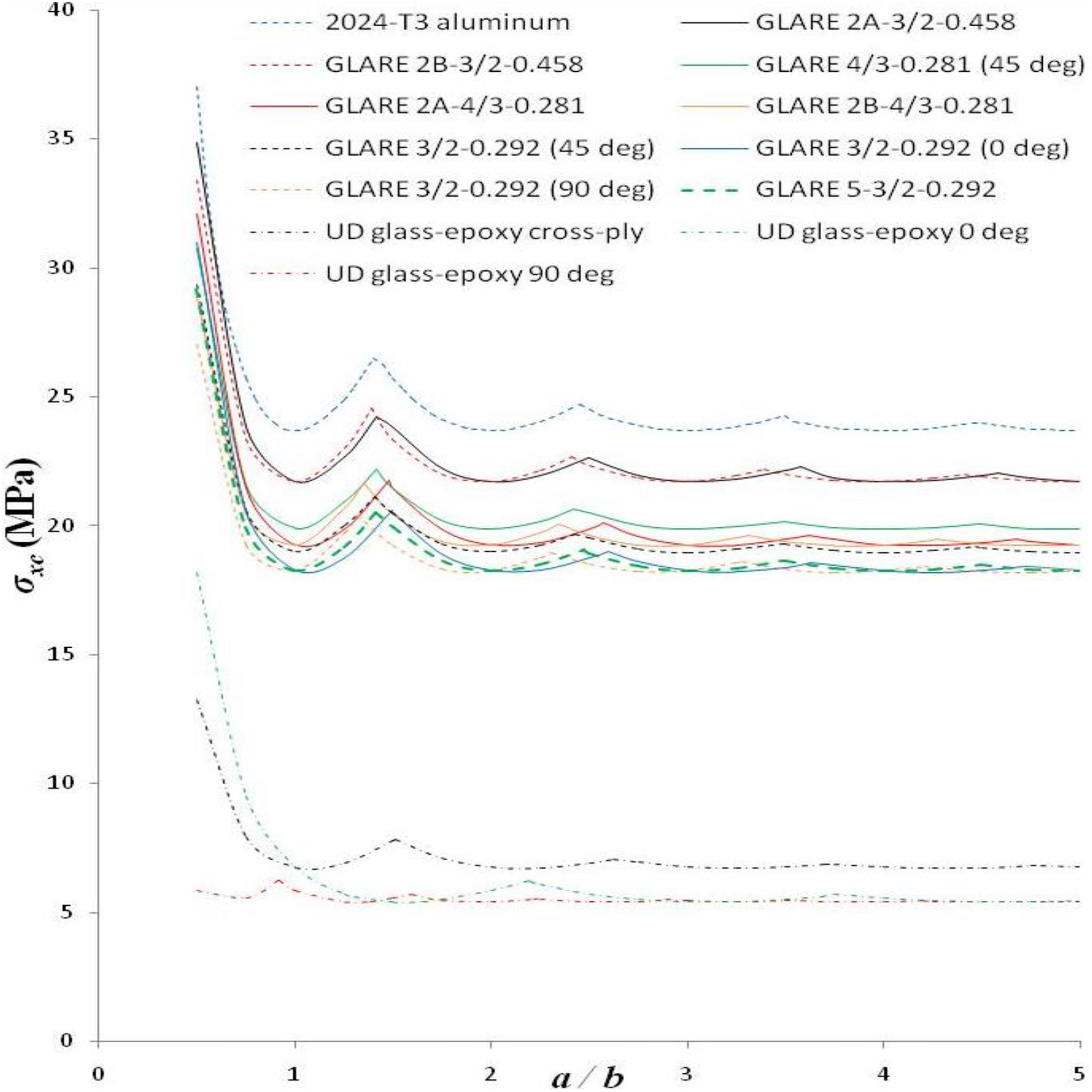
Comparison of average critical buckling stresses of simply supported GLARE, aluminum, and UD composite plates under uniaxial compression.
Comparison of average critical buckling stresses of clamped GLARE, aluminum, and UD composite plates under uniaxial compression.
We have investigated the applicability of the classical rule of mixtures for the calculation of the average critical buckling stress

where
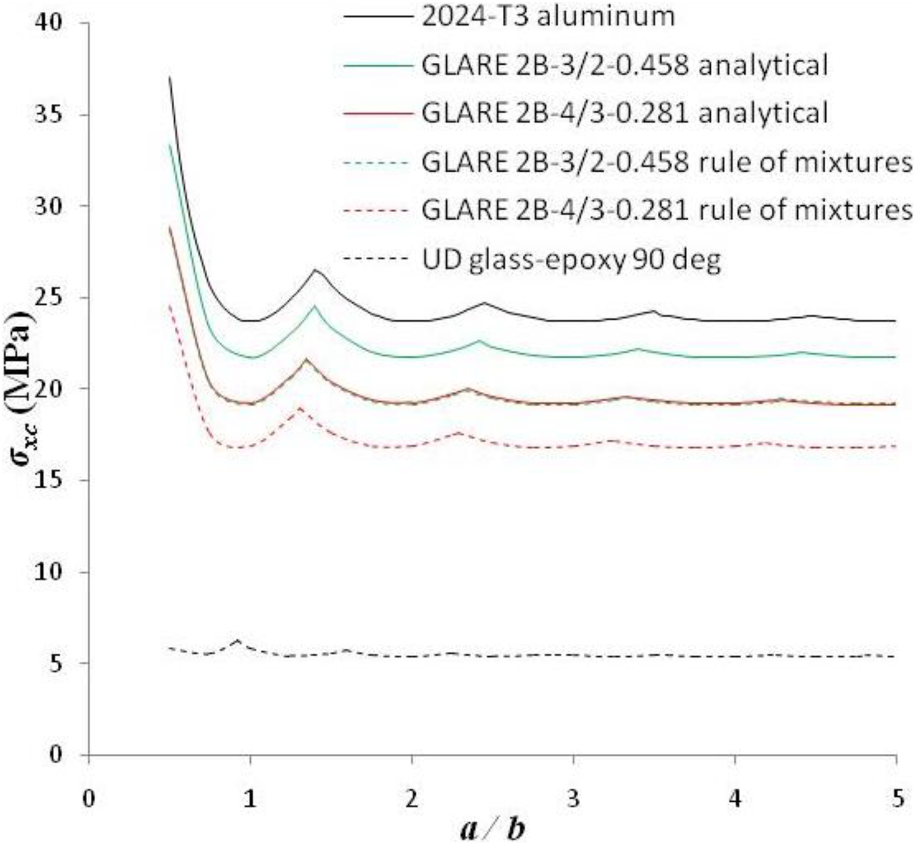
Analytical versus rule of mixtures (equation (9)) average critical buckling stresses of simply supported GLARE 2B plates under uniaxial compression.
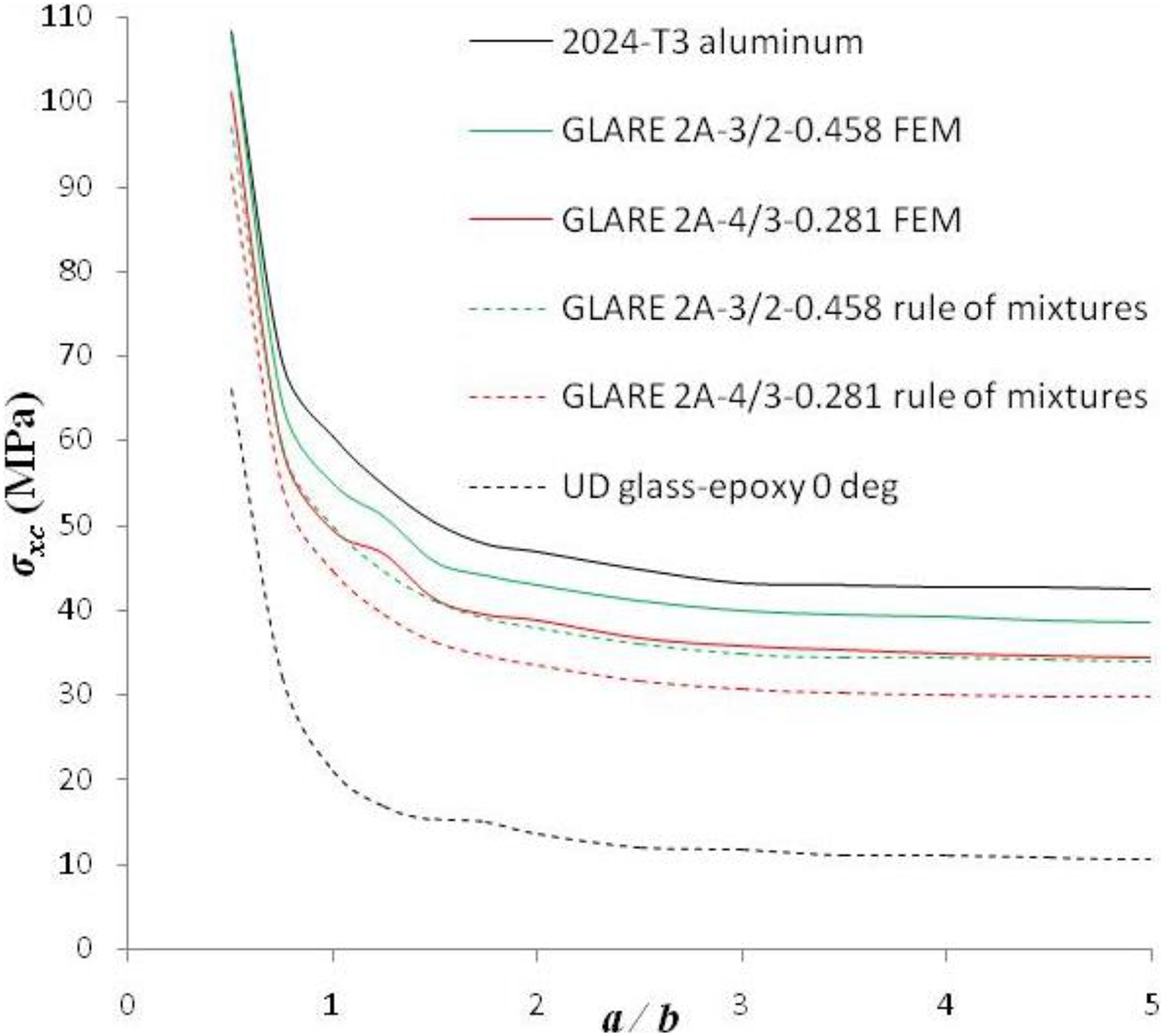
FEM versus rule of mixtures (equation (9)) average critical buckling stresses of clamped GLARE 2A plates under uniaxial compression.
Using equations (1) to (3), the average critical buckling stresses of aluminum, composite, and GLARE plates can be calculated as a function of their buckling coefficient, and by substitution in equation (9) we obtain a very useful relation

where DiiC are the bending stiffnesses of the composite plate, DiiG are the bending stiffnesses of the GLARE plate, kG is the buckling coefficient of the GLARE plate, kC is the buckling coefficient of the composite plate, and kA is the buckling coefficient of the aluminum plate.
Equation (10) can be used in order to estimate approximately the buckling coefficient of a simply supported or clamped GLARE plate when kC and kA are known, provided that the aforementioned conditions for the validity of equation (9) are satisfied here as well. In Figure 11, the buckling coefficients calculated using equation (10) are compared with analytical and FEM calculations for simply supported and clamped GLARE 2A plates. A good agreement between exact and equation (10) based (kG , α/b) curves is found. We have made similar comparisons for the remaining GLARE grades and a good agreement has also been found. These findings demonstrate the validity of equation (10) for the approximate calculation of kG .
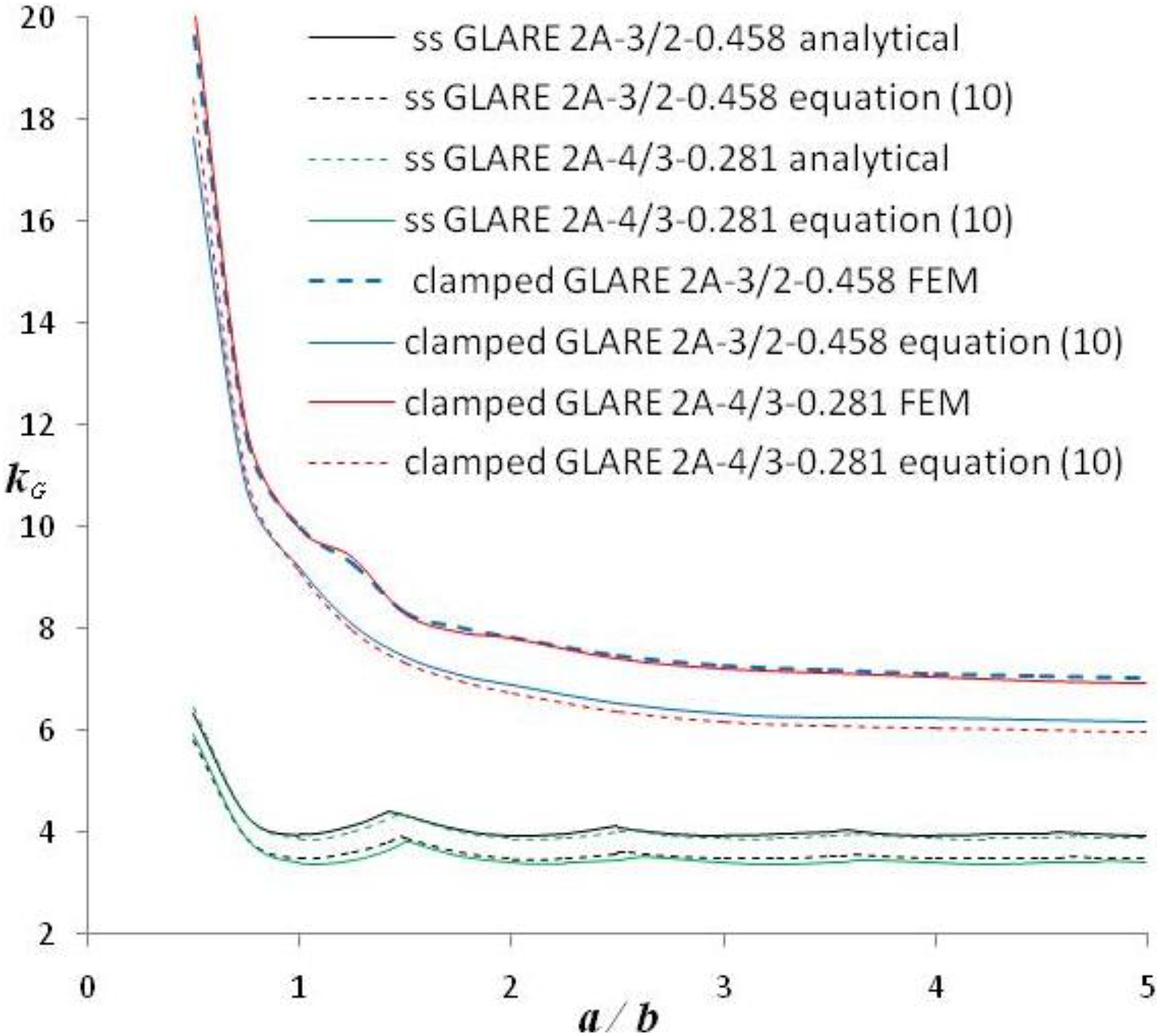
Exact versus approximate buckling coefficients of simply supported (ss) and clamped GLARE 2A plates under uniaxial compression.
We have studied systematically the mode shapes corresponding to the critical buckling load of the examined plates. The buckling mode shape can help the analyst locate the areas that need to be strengthened in order to increase the critical buckling load of the structure. With reference to the simply supported composite laminates and FMLs consisting of specially orthotropic prepreg layers, it is found that the critical mode shape is always symmetric about the plate’s axis of symmetry which is parallel with the loading direction. Each mode shape consists of one or more half-waves arranged along the loading direction, which have the same maximum deflection. These maximum deflections lie into the aforementioned axis of symmetry. The half-waves are located at the same transverse distance from the longitudinal boundaries of the plate. Each half-wave is symmetric about the axes of a Cartesian coordinate system located at the half-wave’s center, which is parallel with the longitudinal and transverse centerlines of the plate. Figure 12 illustrates a representative plot of the deflections corresponding to the critical mode shape of a simply supported GLARE 2A-3/2-0.458 plate with α/b = 3.
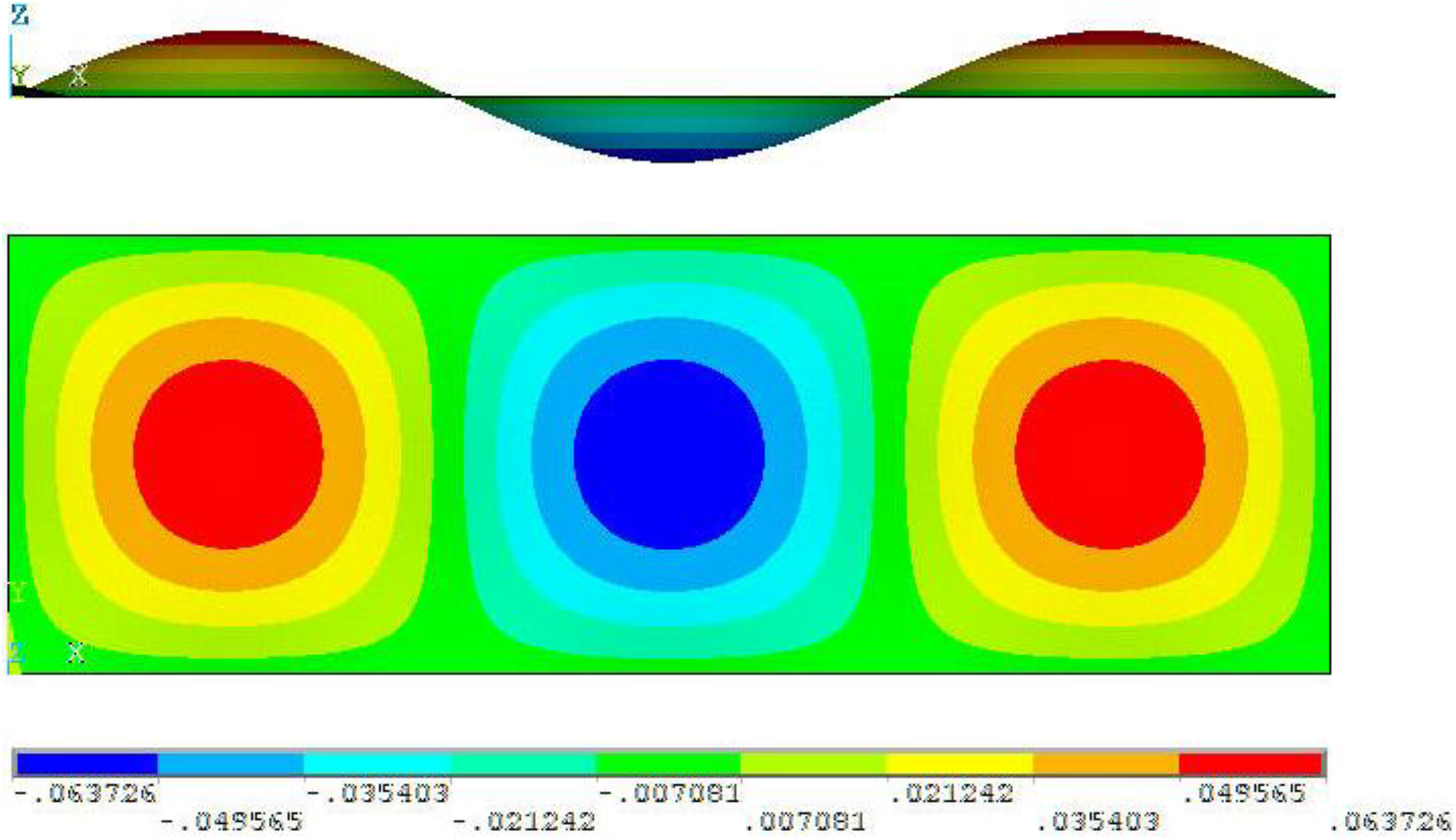
FEM side and top view contours of the deflections corresponding to the symmetric critical buckling mode shape of a simply supported GLARE 2A-3/2-0.458 plate with aspect ratio equal to 3 under uniaxial compression.
Regarding the clamped composites and FMLs consisting of specially orthotropic prepreg layers, the critical mode shapes demonstrate the same symmetry as the aforementioned symmetry of the simply supported plates. Each mode shape consists again of one or more half-waves arranged along the loading direction, which now have decreasing maximum deflections as moving away from the transverse centerline of the plate. The maximum deflections of the half-waves lie into the longitudinal centerline of the plate. The half-waves are not located at the same transverse distance from the longitudinal boundaries of the plate. This is attributed to the variation of the local maximum deflection of each half-wave. A representative plot of the deflections corresponding to the critical mode shape of a clamped GLARE 2A-3/2-0.458 plate with α/b = 3 is depicted in Figure 13.
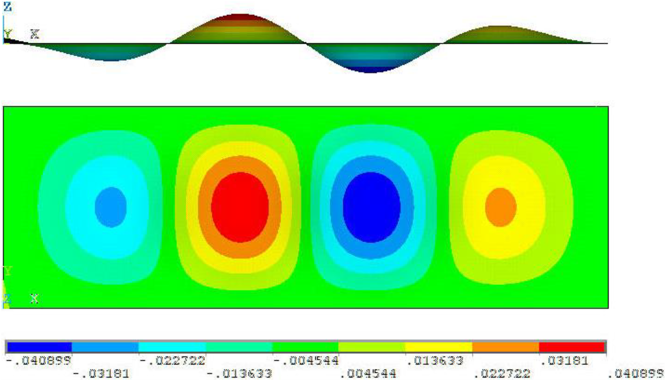
FEM side and top view contours of the deflections corresponding to the antisymmetric critical buckling mode shape of a clamped GLARE 2A-3/2-0.458 plate with aspect ratio equal to 3 under uniaxial compression.
According to FEM results, the critical buckling mode shapes of both simply supported and clamped composite laminates and FMLs with specially orthotropic prepreg layers are symmetric about the transverse centerline of the plate when the number of half-waves is odd. The mode shapes are antisymmetric when the number of half-waves is even. Another finding is that for the same aspect ratio α/b, the clamping of the considered laminates may increase the number of half-waves corresponding to the buckled plate in comparison with the simply supported bc, as in Figures 12 and 13. Furthermore, the clamped bc increase the distance of the half-waves from the boundaries of each plate in comparison with the simply supported bc.
With reference to the analyzed GLARE FMLs with 45° fiber orientation angle, regardless of the examined bc, it is found that the critical mode shapes do not have symmetry or antisymmetry about the centerlines of the plate, as in the case of specially orthotropic laminates. The half-waves are now rotated from the loading direction due to the 45° fiber orientation angle. The half-waves of the simply supported plates do not have the same maximum deflection as in the case of specially orthotropic prepreg layers. The maximum buckled deflections lie again along the longitudinal centerline of the plate, for both types of bc. The half-waves are not located at the same transverse distance from the longitudinal boundaries of the plate, regardless of the bc.
It is known that boron-epoxy and graphite-epoxy 32 fiber-reinforced composites with 45° fiber orientation angle demonstrate a nonlinear stress–strain behavior in in-plane shear. Recently, this nonlinear behavior has been reported for glass-epoxy composites by Taheri-Behrooz and Moghaddam. 33 This behavior, according to Taheri-Behrooz and Moghaddam, 33 can yield about 8% and 4% error in the magnitude of shear strength and shear modulus, respectively, for glass-epoxy specimens used for V-notched rail shear tests. In our analysis, we do not consider this nonlinearity for the composite plies corresponding to the analyzed GLARE FMLs with 45° fiber orientation angle, assuming a linear stress–strain behavior in in-plane shear. The same assumption has been used for the eigenvalue buckling analysis of simply supported and clamped boron-epoxy composites under uniaxial compression with various orientation angles (including 45°), in the study of Whitney. 26 The theoretical buckling calculations implemented by Whitney 26 agree well with corresponding experiments. 26 A good agreement between eigenvalue buckling analysis calculations and experimental data has also been found for boron-epoxy composites with 60° fiber orientation angle and mixed bc under uniaxial compression, in the study of Ashton JE and Waddoups. 34 They also used a linear shear stress–strain relation. In the study of Leissa, 35 a linear bifurcation buckling analysis of simply supported boron-epoxy and graphite-epoxy composites with 45° fiber orientation angle under uniaxial compression has been implemented, assuming a linear shear stress–strain relation, and a good agreement with pertinent experiments has also been found there. It is noted that the aforementioned nonlinearity of glass-epoxy composites 33 is lowered for the considered GLARE plates of this article due to the presence of the aluminum layers.
The increase of the compressed plate’s aspect ratio yields a stepwise increment of the number of half-waves, regardless of the bc and of the considered material.
In Figures 14 and 15, the effect of the MVF on the location of the points of change from one buckling mode of the simply supported plates to another is revealed. The connected line segments in these figures divide the graph into separate areas. In each of these areas, the considered materials will buckle with the same number of half-waves. It is shown from Figures 14 and 15 that as the MVF increases, the points of change are shifted from the locations of UD glass-epoxy, where MVF = 0, and approach the corresponding aspect ratios of monolithic aluminum, where MVF = 100%. Consequently, the variation of MVF can alter the number m of buckled half-waves of plates with equal aspect ratio. For example, when α/b = 2.4, Figure 15 yields that UD glass-epoxy buckles with m = 4, GLARE 3/2-0.292 and GLARE 2B-4/3-0.281 buckle with m = 3, whereas GLARE 2B-3/2-0.458 and monolithic aluminum buckle with m = 2. The effect of the MVF on the location of the points of change is similar for the examined cross-ply laminates as well.
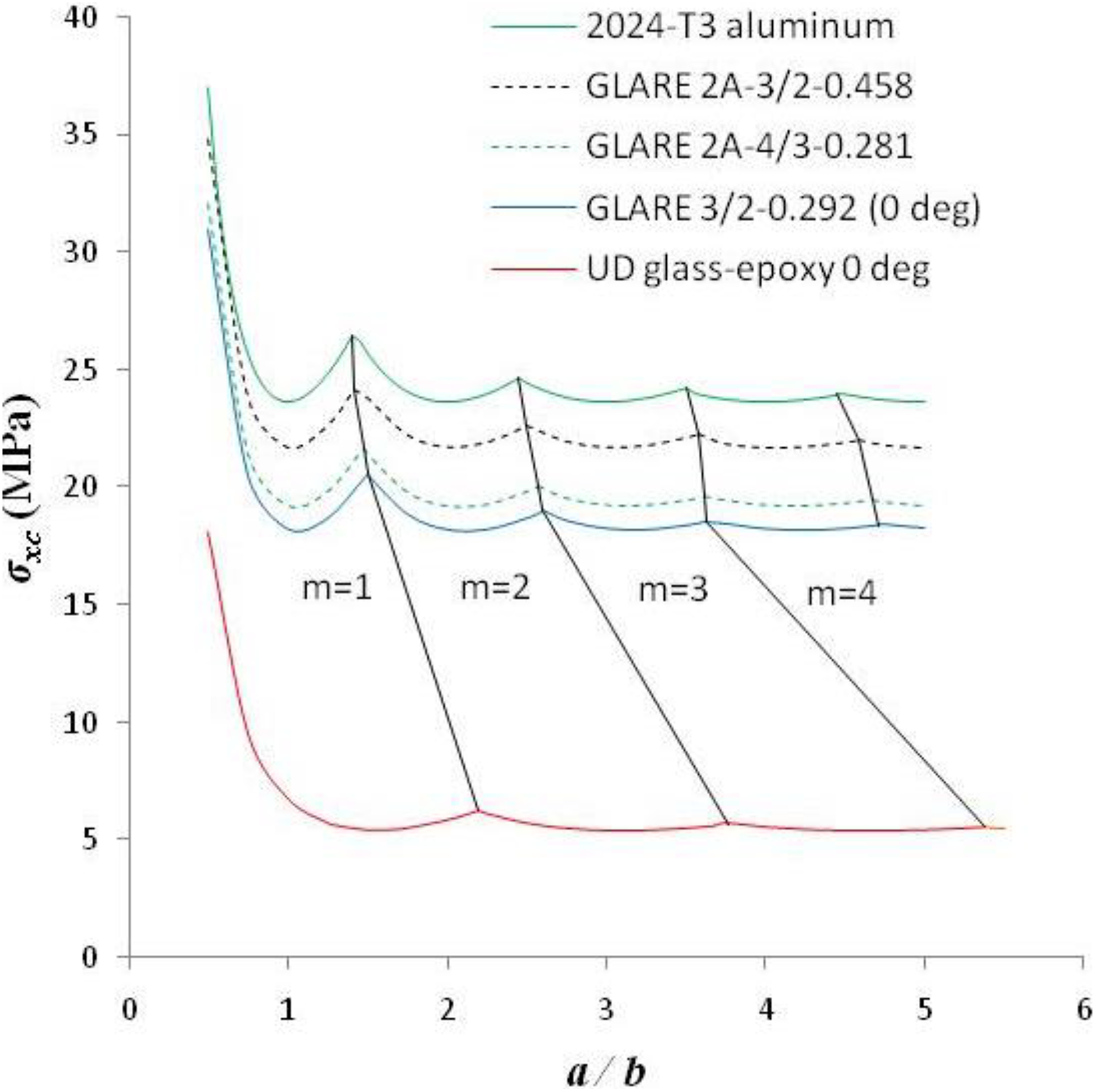
Shifting to the left of the points of change from one buckling mode to another corresponding to simply supported plates under uniaxial compression as the MVF increases.
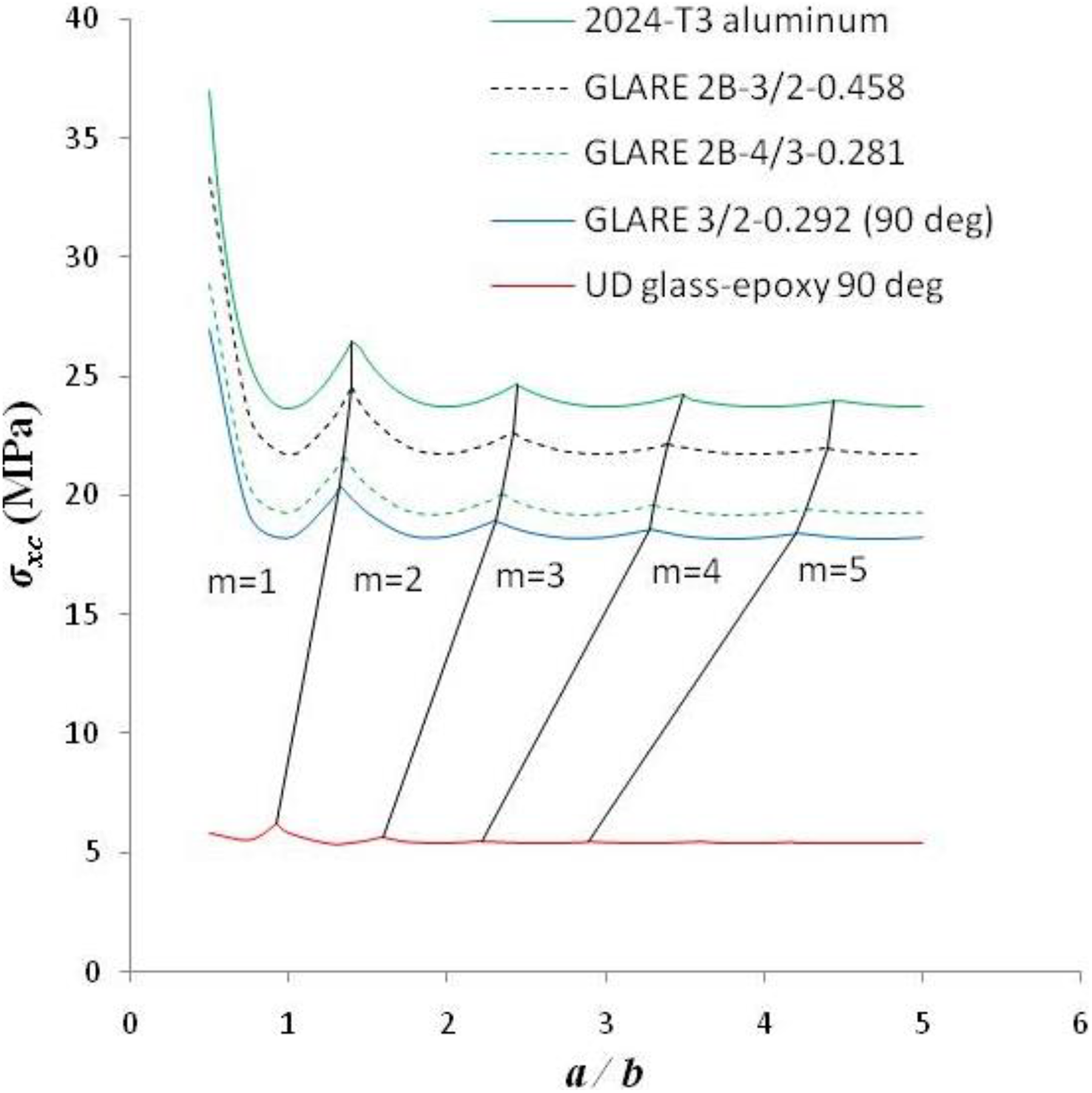
Shifting to the right of the points of change from one buckling mode to another corresponding to simply supported plates under uniaxial compression as the MVF increases.
To the authors’ knowledge, there is not any published scientific literature concerning the elastic buckling response of the analyzed GLARE grades and the comparative evaluation of the buckling strength of the examined materials. Furthermore, equations (9) and (10) are new contributions for the estimation of the elastic buckling strength of FMLs. The presented analysis of the critical mode shapes along with Figures 14 and 15 offer useful unpublished information of the buckling response of FMLs as well.
It is important to discuss the applicability of the presented results to thermoplastic-based FMLs given that such material systems have been manufactured and studied by many researchers. 15 –17,19 The matrix of thermoplastic-based FMLs can be a thermoplastic polymer such as polypropylene 16 and PEEK. 17 The fibers may also consist of thermoplastic polymer such as nylon 66 19 and polypropylene. 16 However, FMLs with thermoplastic matrix and fibers consisting of non-polymeric materials such as glass 17 and carbon 17 have also been manufactured.
Apart from the aforementioned applicability of the finite element modeling procedure to the buckling analysis of thermoplastic-based FMLs, their buckling coefficient-aspect ratio and average critical buckling stress-aspect ratio diagrams can also be derived using the method described in this article for the GLARE laminates. Furthermore, the rule of mixtures as expressed with equation (9) can be applied to thermoplastic-based FMLs for the approximate estimation of their average critical buckling stress. The accuracy of this calculation can be determined with detailed FEM analysis results. Equation (10), which is based in equation (9), can also be applied to thermoplastic-based FMLs in order to estimate approximately their buckling coefficients using the buckling coefficients of their constituents.
It is noted that the same finite element modeling procedure could be applied to thermoplastic-based FMLs in order to obtain their mode shapes. Apart from that, the presented analysis of the mode shapes of this article can help us to analyze the behavior of the mode shapes of thermoplastic-based FMLs. For example, it is reasonable to expect that different bc, clamped or simply supported, will alter the geometry of the mode shapes of thermoplastic-based FMLs accordingly. Also, the role of the MVF on the location of the points of change from one buckling mode to another of simply supported thermoplastic-based FMLs is expected to be similar with the analyzed case of GLARE plates. A 45° fiber orientation angle in thermoplastic composite layers of FMLs is also expected to affect the geometry of the mode shapes accordingly.
Conclusions
This study deals with the elastic buckling of rectangular simply supported and clamped FMLs subjected to uniaxial compression. For the numerical investigation, the finite element method 24 is employed in combination with the eigenvalue buckling analysis in order to predict the buckling coefficient of the laminates and the corresponding mode shape. Nine different GLARE grades are analyzed along with three UD glass-epoxy composites and monolithic 2024-T3 aluminum.
It is found that aluminum has a stronger impact on the behavior of the buckling coefficient-aspect ratio diagrams of the considered GLARE plates than the UD glass-epoxy.
Another finding is that the average critical buckling stress and the buckling load of the 13 materials increases for increasing MVF values, when the plate aspect ratio is greater than 1.5.
It is also found that the rule of mixtures can be applied in order to estimate approximately the critical buckling stress of the GLARE plates. Based on this result, an approximate formula is derived for the estimation of the buckling coefficient of the GLARE plates. It is discussed how these approximations can be applied to thermoplastic-based FMLs.