
Abstract
Within this research, four kinds of multiwalled carbon nanotubes (MWCNTs; 0.0, 0.7, 0.9, and 1.1 wt%) integrated thermoplastic composites with commingled yarns (low melting point polyethylene terephthalate fiber/glass fiber) were fabricated using hot-press machine. The fabricated composites were tested against tensile and three-point flexural loadings. Specimens with 0.9-wt% MWCNTs in 90° direction showed the highest values of tensile and flexural properties with an improvement of about 7% and 33% in tensile and flexural modulus and about 3% and 65% in tensile and flexural strength compared to specimens without MWCNTs in 90° direction. This improvement can most likely be attributed to an increase in interfacial adhesion due to the presence of the carbon nanotubes.
Keywords
Introduction
The necessity for obtaining composite materials, which are characterized by high strength and stiffness, has pushed scientists and researchers to exploit nanomaterial in the fabrication process of composites. 1,2 Multiwalled carbon nanotubes (MWCNTs), 3 a cylindrical nanostructure with diameter in nanometer scale, are famous with their superb properties, in terms of thermal, 4 electrical, modulus, and strength. 5,6 Two main reasons are accountable for the unique properties of the CNTs, 7 one is the interlocking type of the carbon-to-carbon covalent bonds and the second one is the reality that every single carbon nanotube is one molecule, which means no weak spots can be found in the tube structure that could weaken the tube. 8,9 Thus, the incorporation of the nanotubes into the matrix can bring a remarkable improvement to the fabricated composites. 10
At the present time, thermoplastic materials are widely used around the globe in different applications, covering various sectors, such as aeronautic industry, automobile industry, sport and recreation, and many other sectors and applications. 11 Thermoplastics as matrix are replacing metals in most occasions in producing composite materials due to the specifications accompanied by them, such as the lightweight, the relatively low cost, and the recyclability. 12 In order to overcome the high viscosity issue possessed by the thermoplastics polymers, they were produced in the form of fibers. And the thermoplastic polymers were commingled with the reinforcement fibers (also known as commingled yarns) and knitted to form a fabric structure. 13 The commingled yarns technique is featured with the homogeneous distribution of the matrix and reinforcement fibers over the composite cross section. And it raises the properties of the thermoplastic composites to their upper limit. 14 The commingled yarns are usually organized in the form of the non-crimp fabric (NCF) in order to fabricate the composite materials. The NCF is a fabric type that consists of more than one layer with the different orientation of the fibers. The layers of the NCFs were bound together using the binding fibers. Thus, the NCFs can be formed in the biaxial (0°/90° or ±45°), triaxial (0°/+45°/−45°), and quadraxial fabrics (0°/+45°/−45°/90°), depending on the orientation of the fibers in the layers.
Many researchers studied the different parameters of the commingled yarns that could affect the performance and properties of the composites. Long et al. 15 studied the mechanical properties of the composites with the commingled yarn of the glass fibers (GFs)/polypropylene (PP) filaments. Gilchrist et al. 16 studied the fracture and fatigue performance of the textile composites with the commingled yarns. After performing the tension, in-plane shear and flexure tests, they concluded that the warp knitted material was stiffer and marginally stronger when compared to the woven material. Demircan et al. 17 investigated the effect of the various knitting techniques on the mechanical properties of the biaxial weft-knitted thermoplastic composites. They found that the tensile, three-point bending, and three-point bending impact properties of the thermoplastic composites with the commingled yarns could be improved by changing the knitting techniques.
There is a relationship between the molding temperature and the melting temperature of the thermoplastic. Kuzmanovic et al. 18 investigated the effect of injection molding temperature on the morphology and mechanical properties of PP/polyethylene terephthalate (PET) blends and microfibrillar composites. They found that injection molding blends and microfibrillar composites at elevated injection molding temperature (280°C) have shown inferior properties compared to 210°C and 230°C, since the materials have lost their original morphology. Influence of a locally variable mold temperature on injection molded thin-wall components was studied by Fischer et al. 19 Their results showed that the 190°C component regions achieve significantly higher tensile modulus and tensile strength characteristics compared to the 135°C.
Incorporation of the MWCNTs into the thermoplastic composites is expected to show the positive improvements in the mechanical properties of the composites especially in terms of the strength and stiffness, due to all the reasons mentioned earlier. Many research studies were conducted on the incorporation of CNTs into the polymeric matrix composites, most of them used the thermoset polymers as a matrix. Gojny et al. 20 reported the improvement in the modulus, tensile strength, fracture toughness, and anisotropic electrical properties of the composites by adding 0.3-wt% MWCNTs into epoxy matrix. They used the resin transfer molding process in the production of the glass-fiber-reinforced polymers with carbon nanotube/epoxy matrix. Pilawka et al. 21 investigated the enhancements of the mechanical properties of the epoxy composites with carbon nanotubes. They found that introducing carbon nanotubes (0.1, 0.2, 0.5, 1, and 2 wt%) in an epoxy matrix increased the mechanical strength of the thermoset composites. Gojny et al. 22 investigated the influence of the different types of carbon nanotubes on the mechanical properties of the epoxy matrix composites. They used single-walled carbon nanotube, double-walled carbon nanotubes, and MWCNTs in their experiments. They reported that the optimal improvement in the mechanical properties of the composites was achieved using the double-walled carbon nanotubes at 0.5-wt% filler content.
A review of multiscale fiber-reinforced thermoplastic composites incorporating carbon nanotubes was studied by Díez-Pascual et al. 23 Their article reviewed the recent literature on hierarchical thermoplastic-based composites that simultaneously incorporate CNTs and conventional microscale fibers and discussed the structure–property relationships of the resulting hybrids. Liu et al. 24 reported morphology and mechanical properties of MWCNTs-reinforced nylon-6 composites. They prepared MWNTs/nylon-6 (PA6) nanocomposites with different MWNTs loadings (from 0 wt% to 2 wt%) by the simple melt-compounding approach. They found that the elastic modulus and the yield strength of the composite were greatly improved by about 214% and 162% compared to the neat PA6 by incorporating only 2-wt% MWNTs.
Fiber-coated thermoplastic composites were studied before. 25 –27 Effect of fiber coating and geometry on the tensile properties of hybrid carbon nanotube–coated carbon fiber (CF)-reinforced composite was reported by Shazed et al. 25 The growth of CNT on CF was conducted via floating catalyst chemical vapor deposition in their study. They found that the CNT-CF/PP composite compared to the neat-CF/PP composite has shown enhanced Young’s modulus by approximately 104% and tensile strength increased to approximately 64%. Liu et al. 26 investigated the mechanical properties of carbon nanotube/CF-reinforced thermoplastic polymer composite. They fabricated CNT/CF hybrid fiber by sizing unsized CF tow with a sizing agent containing CNT and then they fabricated multiscale composite using CNT/CF hybrid fiber. They found that laminate containing CNTs showed a 115.4% increase in interlaminar shear strength and 27.0% increase in impact toughness. Commingled yarns–processing aspects and tailored surfaces of PP/glass composites were reported by Mader et al. 27 They showed that nanostructured interfaces introduced by smallest amounts of CNTs in sizings enabled to achieve multifunctional effects such as improved tensile strength of GFs, modified morphology of interphases, and new fracture mechanisms.
There are some studies on the improvement of interfacial and mechanical properties of thermoset and thermoplastic composites by incorporating CNT into composites by fiber coating which were explained earlier. Indeed, to the best of authors’ knowledge, incorporating CNTs into composites by fabric coating of CNTs at the interface of fabric layers to improve the interfacial and mechanical properties of thermoplastic composites with commingled yarns of low melting point PET (LPET) fibers and GFs has not yet been published. The purpose of this study is to characterize the mechanical properties of the MWCNTs integrated thermoplastic composites with the LPET/GF commingled yarns. Within this research, we investigated the tensile and flexural properties of the thermoplastic composites with the LPET/GF commingled yarns with the various weight percentages of the MWCNTs. We also investigated the mechanical properties of the thermoplastic composites in various directions (90°, +45°, and −45°). The obtained results of our study can be used for the design of the new MWCNTs integrated thermoplastic composites.
Experimental procedures
Composite constituents
The NCFs consists of the 0°/90° biaxial commingled yarns with the LPET fibers/GFs. The NCFs were obtained from Metyx Composites Corporation, Istanbul/Turkey, and they were used for fabricating the thermoplastic composites. The total weight of the NCF is 763 g/m2. NCFs consist of two layers of the fabric, one has a 90° orientation and the other has 0° orientation of the biaxial commingled yarns. The 0°/90° fiber layers of the NCFs are bounded together using the binding fibers made of polyester (76 dtex) as can be seen in Figure 1. In the NCF fabrics, the number of binding yarns per inch was 5 (density of binding yarn) and the lengths of binding yarns are 3 mm. The composition of the commingled yarns and other specifications can be found in Table 1. The specifications of MWCNTs are given in Table 2. MWCNTs were supplied from Ege Nanotek Kimya Sanayi, Izmir/Turkey.
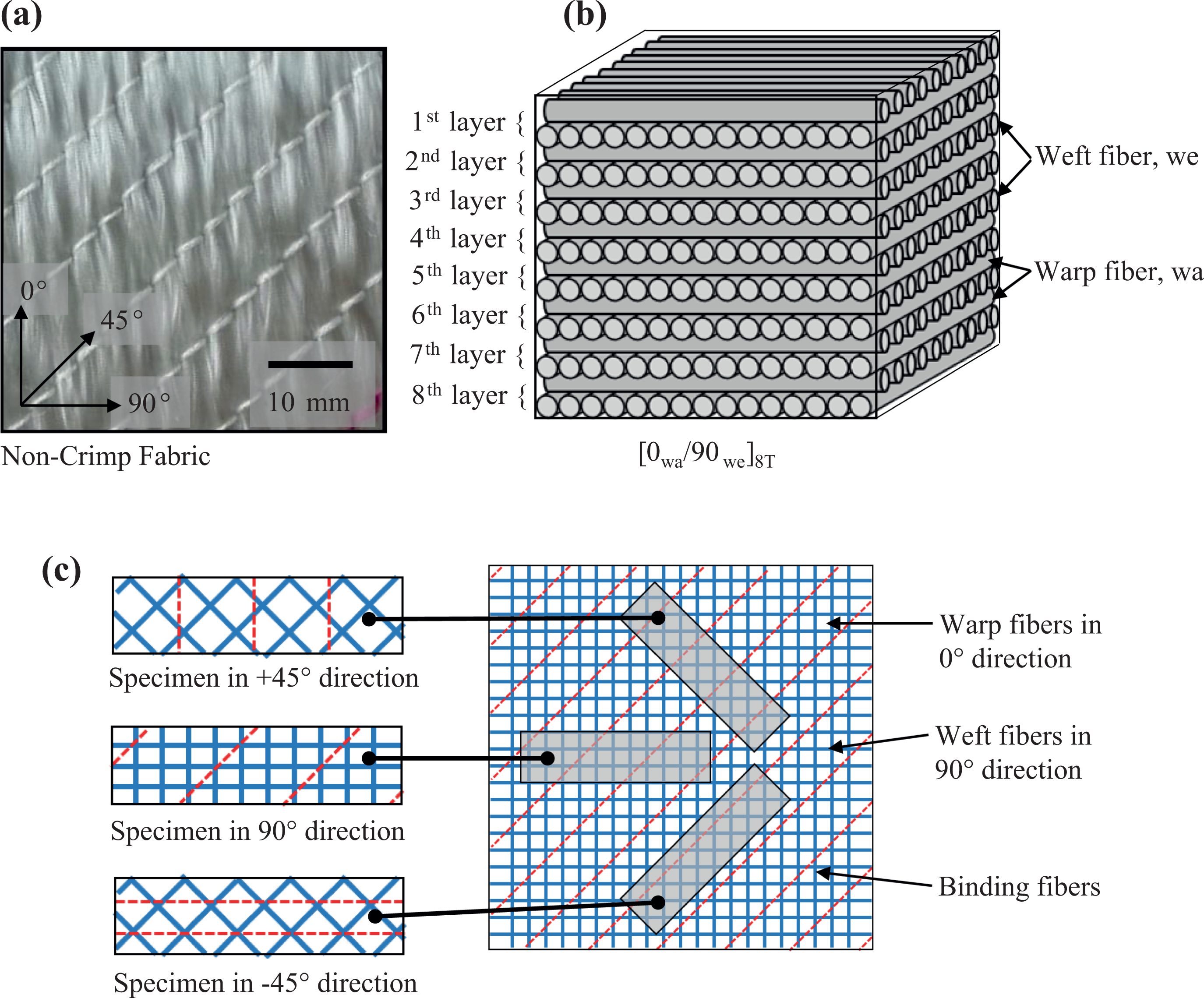
(a) Real image of biaxial NCF, and (b) schematic drawing of biaxial NCF.
Specifications of non-crimp fabric.
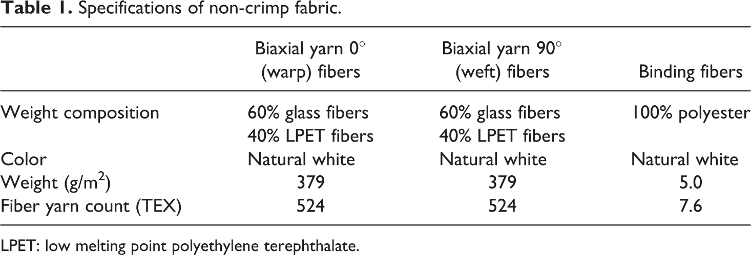
LPET: low melting point polyethylene terephthalate.
Properties of MWCNTs.
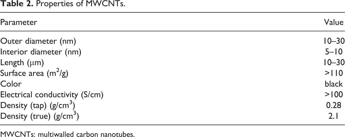
MWCNTs: multiwalled carbon nanotubes.
Fabrication method
Ethanol were used as the dispersing agent of the solution of the nanomaterials due to its compatibility with MWCNTs and the LPET/GF. The first stage of the dispersing of MWCNTs in the ethanol starts with the magnetic stirrer device, in which the MWCNTs distributed all over the ethanol using a magnet bar, stirred by a magnetic field. The second stage of the dispersing of MWCNTs in the ethanol was implemented using an ultrasonic technique. In this process, MWCNTs dispersed homogenously in the ethanol. 28,29
The different weights of MWCNTs were used in preparing the solution during this study. The aim of using the different weights of MWCNTs was to investigate the effect of different amounts of MWCNTs on the mechanical properties of the fabricated thermoplastic composites. Hence, the optimal percentage of MWCNTs in the composites could be found. The weights of used MWCNTs in our experiments and their final percentages in the fabricated composite were (i) 0.4 g of MWCNTs/0.7 weight percentage of MWCNTs in the composite (0.7-wt% MWCNTs), (ii) 0.5 g of MWCNTs/0.9 weight percentage of MWCNTs in the composite (0.9-wt% MWCNTs), and (iii) 0.6 g of MWCNTs/1.1 weight percentage of MWCNTs in the composite (1.1-wt% MWCNTs).
Figure 2(a) to (e) shows the preparation process of the MWCNTs-coated NCF. The dimensions of the NCF specimens were (20 × 20) cm2. Both faces of the two layers of the NCF were coated by the prepared solution (i.e. four faces of the NCF were coated with each prepared solution). Figure 2(d) and (e) shows the NCF specimen before and after coating, respectively.
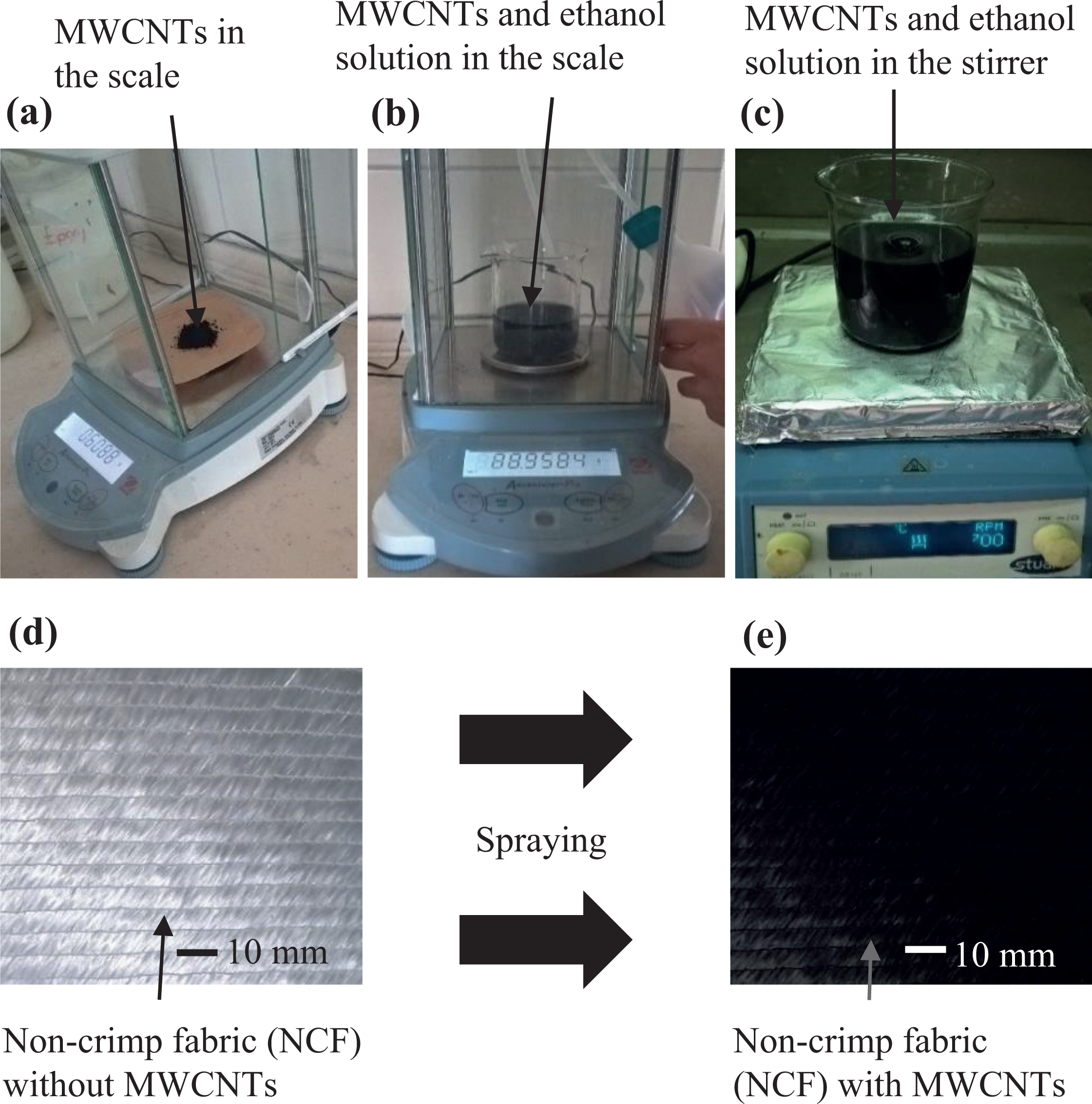
Preparation process of the MWCNTs-coated NCF.
After coating NCF with the MWCNTs solution, the specimens were left for 2 days in the room temperature to ensure the full evaporation of the ethanol. The hot-press machine (MSE Technologies, Kocaeli, Turkey) was used to fabricate the thermoplastic composites. Two ([0wa/90we]2T) and eight layers ([0wa/90we]8T) of nonsymmetric of the 0°/90° biaxial NCFs were positioned inside a mold, which was made of the copper and placed between two heaters of the hot-press machine. Figure 1 shows a schematic drawing of the stacking sequence of the thermoplastic composites as well as the sampling method. The molding pressure and temperature were 17 bar and 165°C. Then, the specimens were cooled down to the room temperature. The same temperature and pressure values were used for all of the fabricated specimens. The fabricated composite plates were prepared for the mechanical tests by assigning three different directions of the specimens (Figure 1).
After fabricating the composites, burn off method in a muffle furnace was performed in order to determine the percentages of each of the constituents in the thermoplastic composites. The burn off process of the composites was conducted according to the ASTM D3171-99 standards. The volume and weight fractions of all the specimens of the tensile (two layers) and three-point flexural (eight layers) tests can be seen in Table 3.
Weight and volume fractions of composites for the tested specimens.
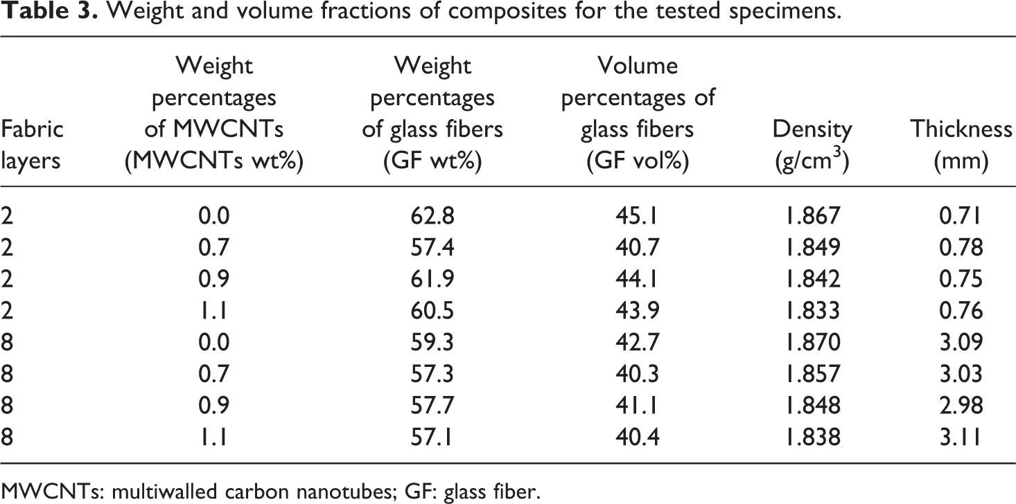
MWCNTs: multiwalled carbon nanotubes; GF: glass fiber.
Characterization
Fourier transform infrared (FTIR) spectroscopy analysis was performed in a Bruker Tensor 27 FTIR (Germany). Scanning electron microscopic (SEM) and optical microscopic (OM) images were obtained in a JSM-7001 F analytical field-emission SEM (Japan) and Leica DM 4500 OM apparatus (Germany).
Two mechanical characterization tests were conducted on the specimens, such as tensile and three-point flexural tests. For the tensile tests, two layers of the NCFs were used for fabricating the specimens. The dimensions of the sample of the tensile tests were set according to the ASTM-D3039 standards. The universal testing machine type of INSTRON 5982 100KN (USA) with tensile and flexural test apparatus was used for performing the tensile and three-point flexural tests. The linear displacement speed was 1 mm/min in the tensile and three-point flexural tests. Figure 3(a) shows the side and top views of the samples used for the tensile test, in which T sp and T Al represent the thickness of the specimen and the thickness of the aluminum tab, respectively. T sp and T Al were 0.7 and 0.2 mm, respectively. The width and length of the specimens were 20 and 160 mm, respectively, in the tensile tests. For three-point flexural tests, eight layers of the NCFs were used and the ASTM-D790-03 standards were followed for preparing the specimens. The dimensions of the specimens (Figure 3(b)) were 80 mm in length, 15 mm in width, and 3 mm in thickness. The span length was changeable according to the value of the thickness and it was ranged between 48 mm and 52 mm. In the tensile and three-point flexural tests, three specimens were tested in −45°, +45°, and 90° directions for each type of the composite panels.
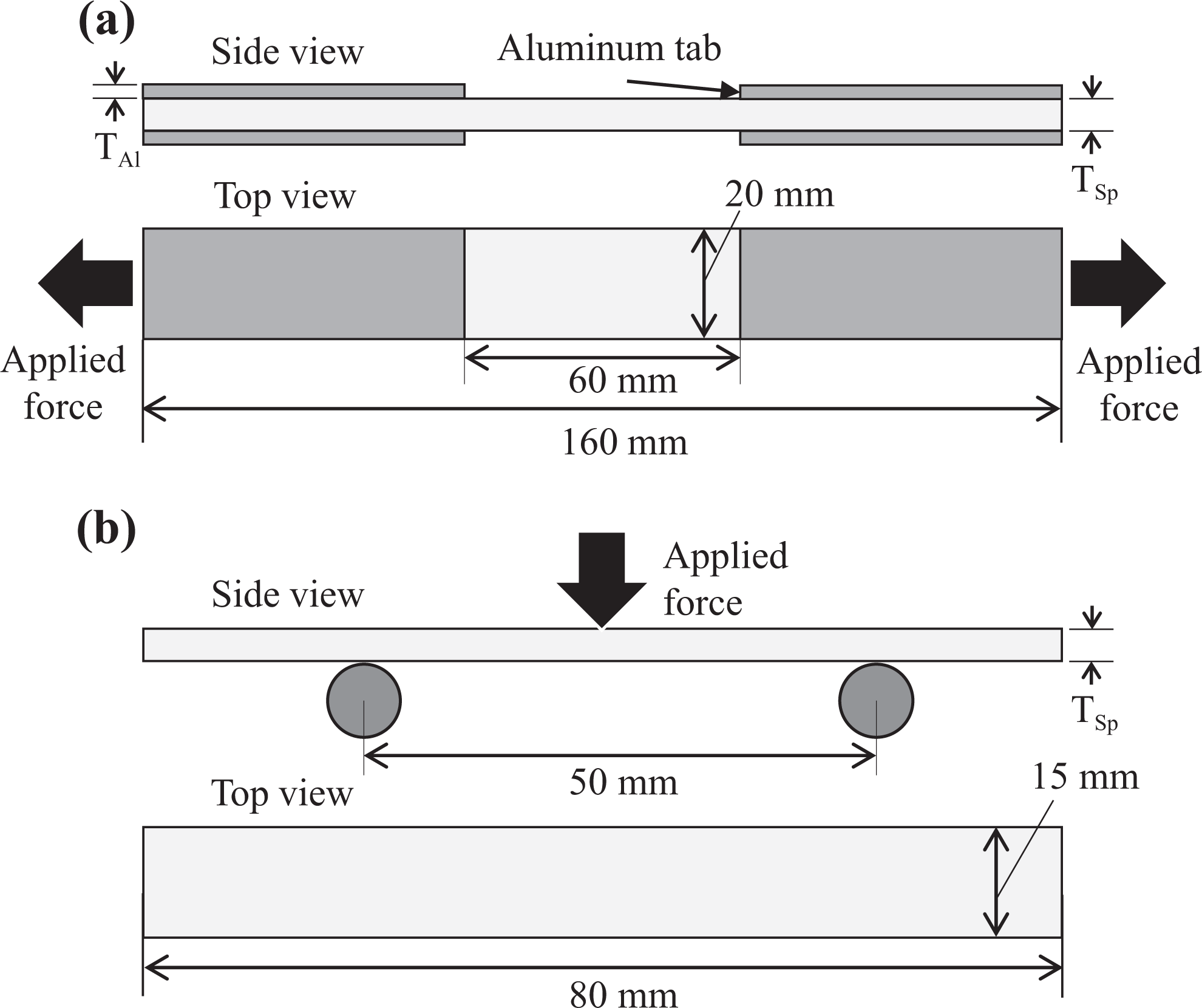
Dimensions of specimens for (a) tensile test and (b) three-point flexural test.
Results and discussion
Surface characteristics of CNT-grafted fibers
The SEM images of the surface morphologies of LPET-glass commingled fibers after grafting CNTs are shown in Figure 4(a) to (d). Figure 4(a) indicates the SEM image of an individual GF after the CNT grafting process. The GF surface was fairly covered by homogenous CNT layer but rarely uncoated regions on the fiber surface were also observed. The high magnification SEM image of the individual CNT-grafted GF is shown in Figure 4(b). The CNTs on the GFs were mostly distributed homogenously; however, a few CNTs agglomerations with the diameter of around 1 µm were monitored. It is clear that those homogenously distributed CNTs play an important role considering interfacial interactions between the CNTs-grafted fiber–matrix interface and the additional toughening mechanisms including CNT bridging and pullout. Additionally, an individual CNTs-grafted LPET fiber exhibits randomly oriented nonuniform CNT dispersion on the fiber, and fairly CNT agglomerations were also observed (Figure 4(c)). The high-magnification SEM image of the LPET fiber shows individually distributed CNTs on the fiber surface out of the agglomerated regions. It is clear that the higher surface roughness of the LPET fiber compared to the glass counterpart leads hooking of the CNTs and results in increasing of agglomerated CNTs regions on the fiber surfaces (Figure 4(d)).
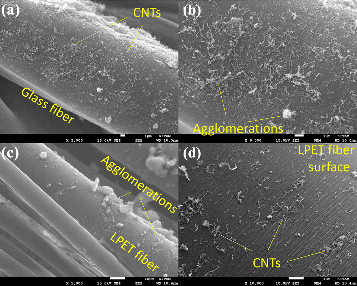
SEM images of surface morphologies of LPET-glass commingled fibers after grafting CNTs.
FTIR spectroscopy is a well-used qualitative technique for the evaluation of the chemical structure. FTIR spectrum of MWCNTs indicates the existence of notable amount of functional groups on the nanotube surface as in Figure 5(a). The peak at 3731 cm−1 is attributed to free hydroxyl groups. The bands at 2989 and 2904 cm−1 correspond to the stretching vibrations of the C–H bonds revealing the –CH3 absorption on the nanotube surface. It is usually assumed that these groups are located at defect sites on the sidewall surface. The peaks appearing at 2327 and 2329 cm–1 are assigned to hydrogen bonding due to the –COOH groups present. 30 –32 Even if we utilized nonfunctional MWCNTs in this study, a small amount of functional groups can exist on the nanotube surface depending on the production process of the nanotubes. 33 The FTIR spectrum of LPET/GF represents both components as shown in Figure 5(b). The four major peaks associated with the inherent structure of the PET were the terephthalic acid ester C=O group at 1715 cm−1, the asymmetric C–C–O and the O–C–C stretching at 1240 and 1092 cm−1, respectively, and the C–H wagging vibrations from the aromatic structures at 722 cm−1. 34 The band located at 1599 cm−1 is attributed to the N–H deformation which indicates the existence of amine-based organo silane modification on the fiber surface. The band at 1396 cm−1 corresponds to C–O stretch vibration of the free carboxylic acid groups. The band centered at 1016 cm−1 is assigned to the asymmetric stretching vibration of Si–O–Si bonds. The band at 879 cm−1 reveals the existence of silanol groups on the fiber surface. 30,31 After coating non-crimp LPET/GF with MWCNTs, we did not observe any drastic changes on the characteristics, wave numbers, and intensities of the spectrum (Figure 5(c)). This observation indicates that there are only physical interactions between the NCFs and MWCNTs. It must be said that the chemical interactions do not occur at this stage since the MWCNTs-coated NCFs were dried at room temperature for 2 days. However, the fabrication process of the composite laminates includes hot pressing with high temperature (160°C), and these process conditions lead the formation of chemical bonds between functional groups such as –CH3 and –COOH on the MWCNT surface and the free silanol groups on the GF surface. Specifically, it is clear that the intensity of the band at 2353 cm−1 attributed to oxygen-containing groups decreases which indicates chemical bonds are established. Therefore, we can confidentially claim that holding the MWCNTs-coated fabrics at this temperature establishes chemical bonding between the functional groups on the nanotube surface and LPET/GF in NCFs. 30,31
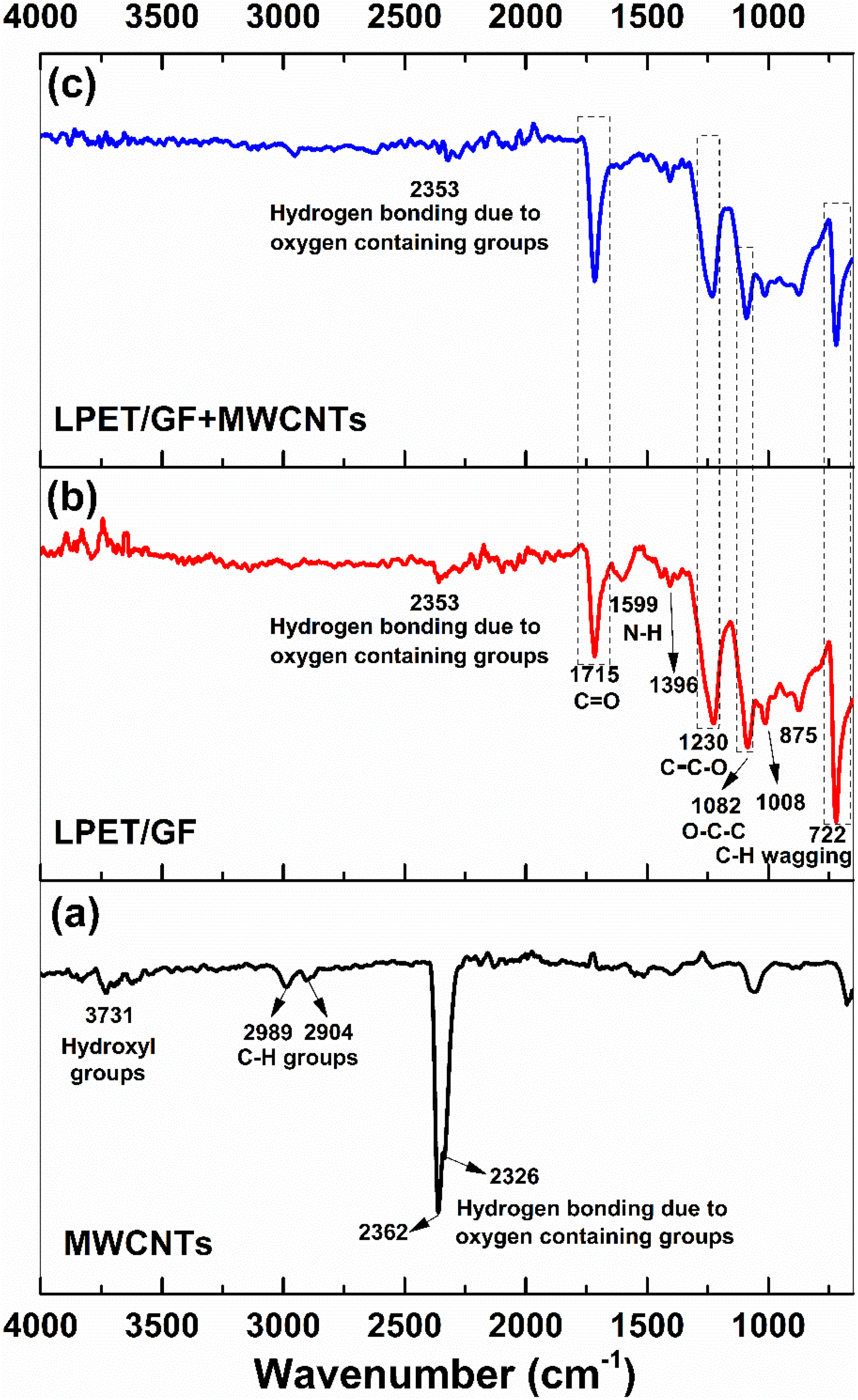
Results of FTIR characterization.
Tensile properties
Figure 6(a) to (c) shows the graphs of the stress–strain curves from the tensile test. As can be seen in all of the graphs, the tensile stress starts increasing linearly with the increasing in strain. Then, a sudden decreasing in tensile stress happens. In Figure 6(a) to (c), the specimens with 0.9-wt% MWCNTs had the highest tensile stress among other specimens, while the specimen with 0.0-wt% MWCNTs showed the lowest tensile stress.
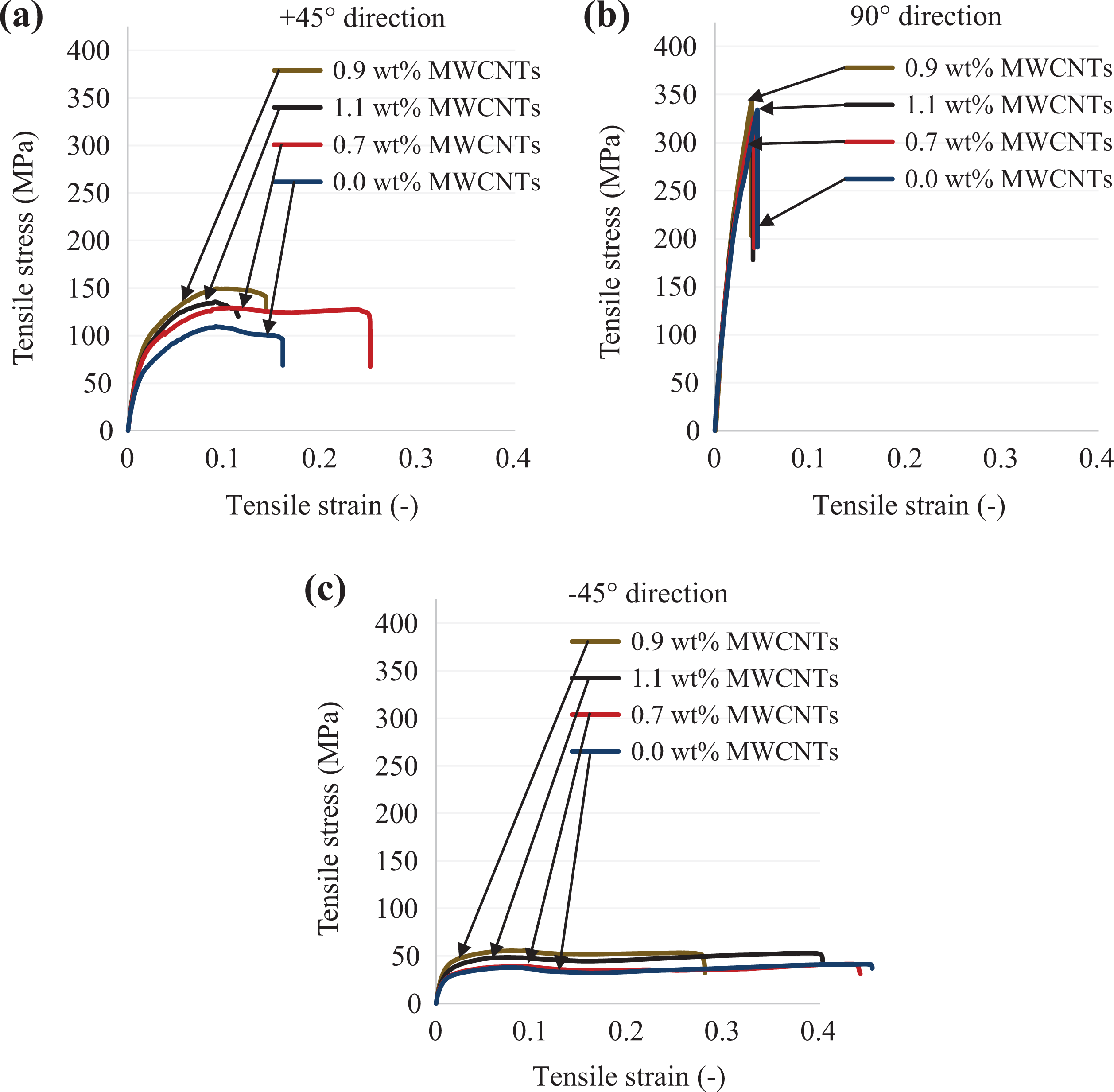
Stress–strain curves from tensile test: (a) in +45° direction, (b) in 90° direction, and (c) in −45° direction.
Figure 7 shows the results of the tensile modulus and strength of all the specimens. The specimens in 90° direction with 0.9-wt% MWCNTs had the highest values of the tensile modulus (15.1 GPa) and strength (343 MPa) among their groups. The specimens in −45° direction with 0.0-wt% MWCNTs had the lowest value of tensile modulus (3.4 GPa) and strength (41.4 MPa). The tensile modulus and strength were improved 7% and 3% for the specimens with 0.9-wt% MWCNTs compared to the specimens with 0.0-wt% MWCNTs in 90° direction. The tensile modulus and strength were improved 36% and 35% with 0.9-wt% MWCNTs compared to 0.0-wt% MWCNT in +45° direction. That was 56% and 34% in −45° direction. The possible reason for obtaining the improved tensile properties for the specimens incorporated into the MWCNTs was the synergy between fiber and matrix, which was created by the MWCNTs in the composite material.
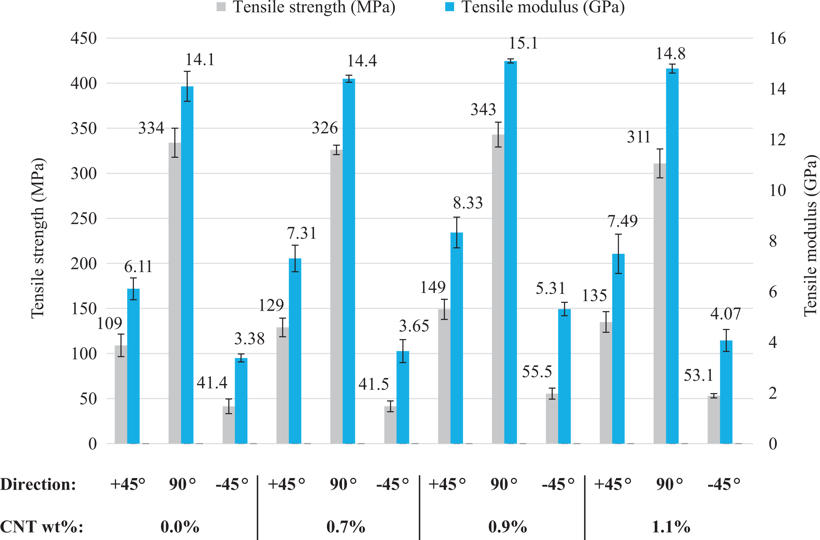
Results of the tensile modulus and strength of all the specimens.
Due to the orientation of the 90° reinforcement fibers in the direction of pulling (Figure 1(c), 90° direction), the specimens in 90° direction can resist more tensile load than the others. Therefore, the specimens in 90° direction had the highest tensile modulus and strength compared to the others.
Despite the fact that the specimens in +45° and −45° directions had the same reinforcement orientation (Figure 1(c)), they showed the different results of the tensile tests. And the tensile properties of the specimens in +45° direction were higher than −45° direction. This was primarily because of the orientations of the binding fibers. The binding fibers acted as a holder for the fiber bundles in +45° direction of the samples by preventing them from dissipation, when a force applied. Therefore, the results of the tensile tests in +45° direction was higher compared to the −45° direction.
The fracture aspects after the tensile test of the specimens with 0.7-wt% MWCNTs in 90°, +45°, and −45° directions were shown in Figure 8(a) to (c). The fracture aspects of the specimens had good agreement with the tensile test results. The photo of the fractured specimen in 90° direction was shown that the path of the fracture was perpendicular to the pulling direction of the specimen (Figure 8(a)). This was proved that the specimens in 90° direction showed higher resistance against the tensile loading. And it resulted in the highest tensile properties of the specimens in 90° direction compared to the others. The path of the fracture was the same as the direction of the 0° and 90° reinforcement fibers in +45° and −45° directions. Both specimens in +45° and −45° directions showed similar fracture aspects after the tensile tests (Figure 6(b) and (c)). The longer ends of the fractured fibers in Figure 6(b) and (c) proved that the specimens in +45° and −45° directions showed the lower resistance against the tensile loading.
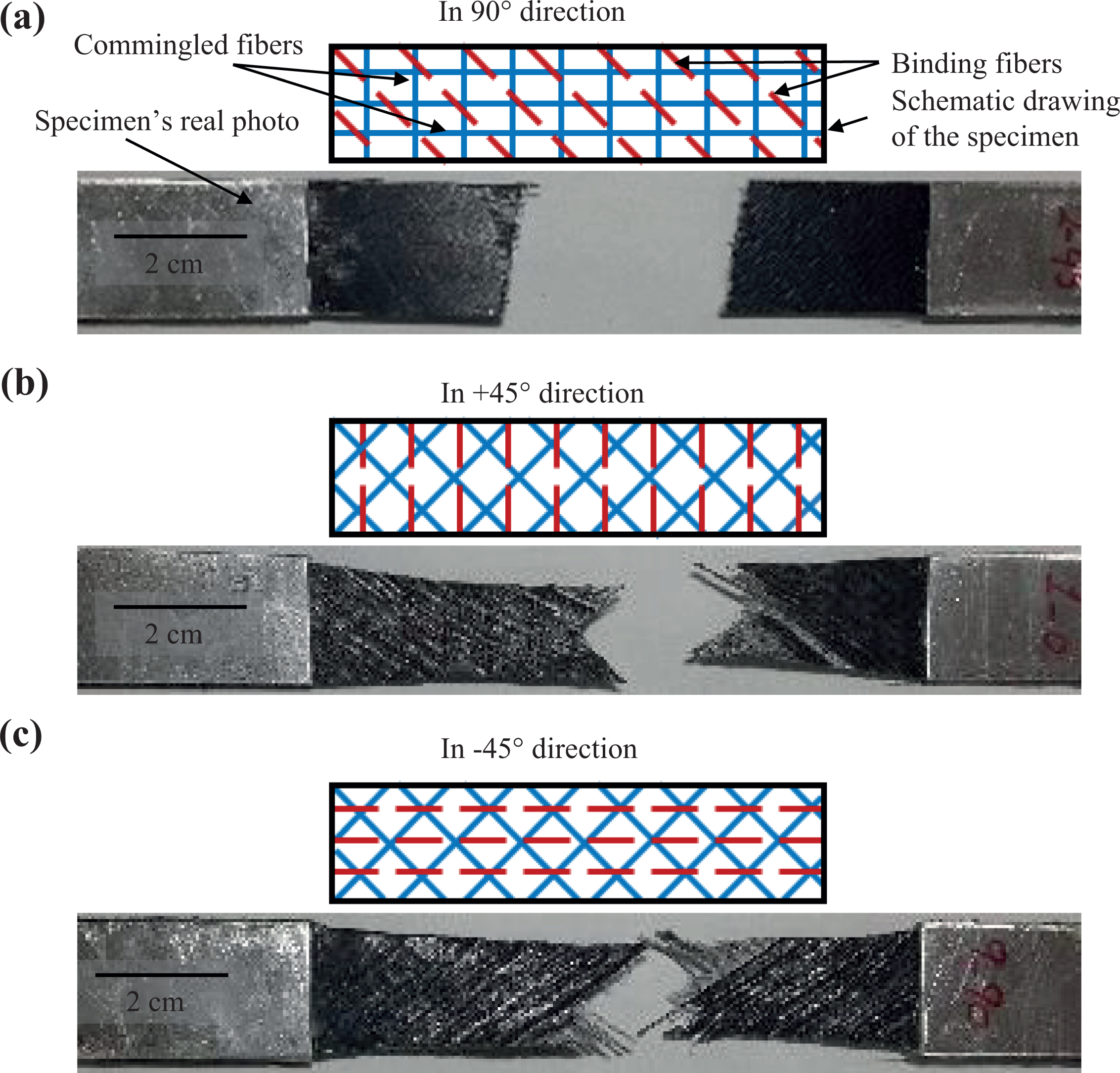
Fracture aspects after the tensile test of the specimens with 0.7-wt% MWCNTs in (a) 90°, (b) +45°, and (c) −45° directions.
Three-point flexural properties
The flexural stress of the composites was defined as its ability to resist the deformation under the bending load. Figure 9(a) to (c) shows the stress–strain curves from the three-point flexural test. In Figure 9(a) to (c), the specimens with 0.9-wt% MWCNTs had the highest flexural stress among other specimens, while the specimen with 0.0-wt% MWCNTs showed the lowest flexural stress.
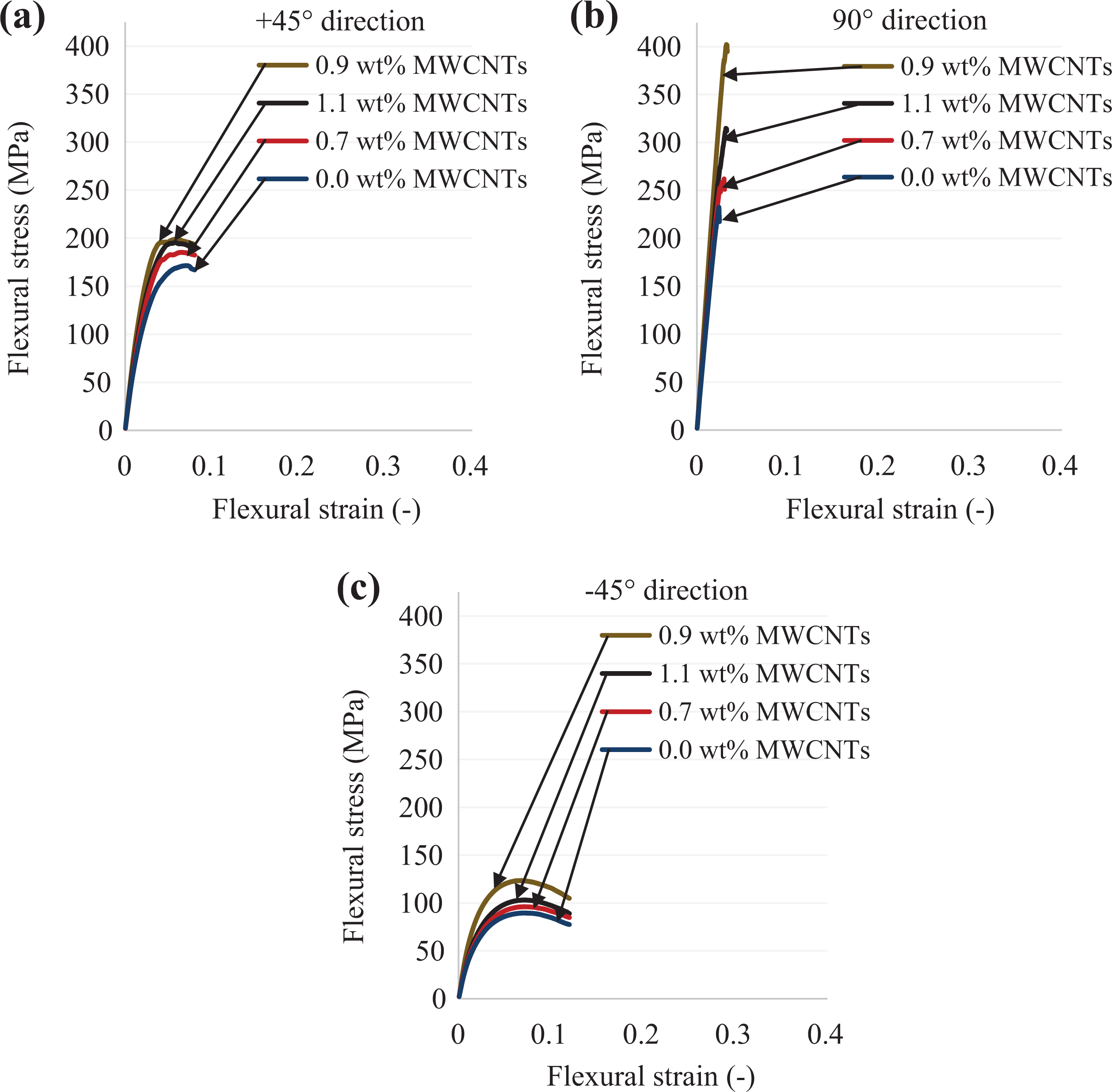
Stress–strain curves from three-point flexural test: (a) in +45° direction, (b) in 90° direction, and (c) in −45° direction.
Figure 10 represents the results of the flexural modulus and strength of the specimens. The flexural modulus and strength of the composites were improved by increasing the addition of MWCNTs from 0.7 wt% to 1.1 wt%. Regardless of the directions of the specimens, the 0.9-wt% MWCNTs had the highest flexural modulus and strength among their groups. The specimens in 90° direction with 0.9-wt% MWCNTs had the highest values of the flexural modulus and strength (14.1 GPa and 402 MPa, respectively). The specimens in 90° direction with 0.9-wt% MWCNTs showed 33% and 65% higher flexural modulus and strength compared to the specimen with the same direction but without MWCNTs. The specimens with 0.9-wt% MWCNTs had an improvement of 32% and 16% in the flexural modulus and strength compared to the specimens with 0.0-wt% MWCNTs in +45° direction. That was 50% and 38% in −45° direction. The specimens with the 1.1-wt% MWCNTs had the second best results in terms of the flexural properties, followed by the specimens with the 0.7-wt% MWCNTs. The lowest values were obtained from the specimens without MWCNTs. As mentioned earlier, the possible reason for obtaining the improved tensile properties for the specimens incorporated into the MWCNTs was the synergy between fiber and matrix, which was created by the MWCNTs in the composite material.
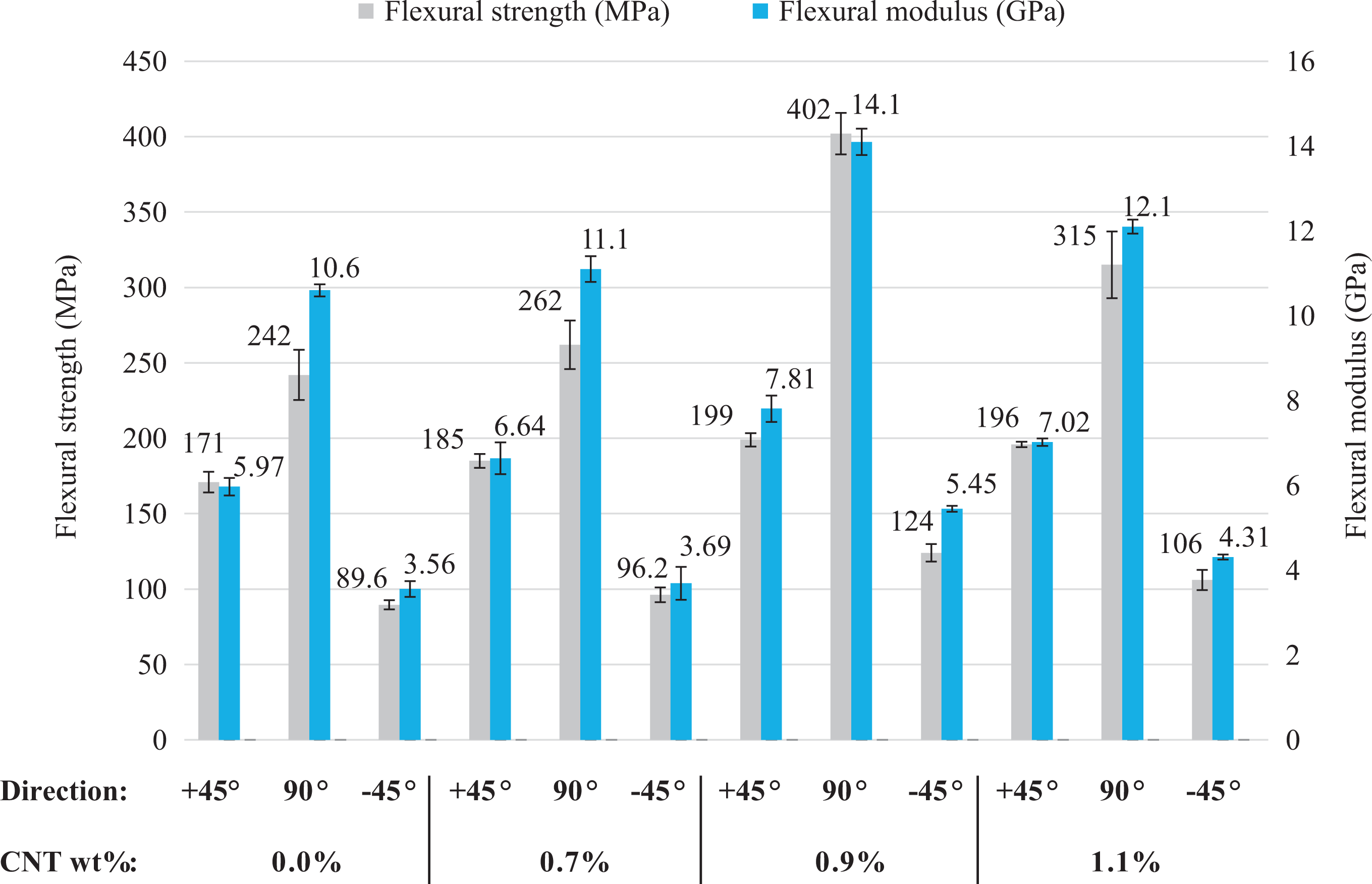
Results of flexural strength and flexural modulus.
The results of the flexural modulus and strength of the composites were started to decrease after 0.9 wt% of MWCNTs. However, the results with 1.1-wt% MWCNTs were still higher compared to the 0.0 wt% of MWCNTs. Our results showed good agreement with the results of Zhou et al. 35 and Shen et al. 36 The mechanical properties of composites were improved by the addition of the CNTs in the polymer matrix, after that the mechanical properties started to decrease in the studies of Zhou et al. 35 and Shen et al., 36 but it was still higher compared to composites without CNTs. This can be explained by several reasons. In the work of Shen et al., 36 the improvement of the mechanical properties of thermoplastic glass/PA6 composites with 2-wt% CNT was higher compared to the 4-wt% CNT. By the addition of CNTs, the viscosity of the matrix was increased and this caused uneven wetting and impregnation of the GF tows. And this was the reason of the lower improvement of the mechanical properties of the composites with 4-wt% CNT compared to the 2-wt% CNT. Furthermore, in the work of Choi et al. 37 and in the work of Ning et al., 38 porosity may have decreased the mechanical properties of the composites with CNTs. Choi et al. 37 reported that few voids were produced during the fabrication process and they found that the void increases with the fiber content of the epoxy/vapor grown carbon nanofiber composites.
The specimens with 90° direction demonstrated better results compared to the others due to the orientation of the 90° reinforcement fibers. Some of the reinforcement fibers were parallel and some of the reinforcement fibers were perpendicular against the applied forces (Figure 1, 90° direction). Due to a perpendicular orientation of the reinforcement fibers against the applied flexural forces, the specimens with 90° direction demonstrated more resistance against the flexural loads. And it resulted in higher flexural properties of the specimens with 90° direction compared to the +45° and −45° directions. The specimens in +45° direction were shown better flexural results than the specimens in −45° direction. As mentioned earlier, the binding fibers hold the reinforcement fibers together in the specimens with +45° direction, while the binding fibers had lower effect in the specimens of −45° direction.
The fracture aspects after the three-point flexural tests of the specimens with 0.7-wt% MWCNTs in +45°, 90°, and −45° directions can be seen in Figure 11(a) to (c). The photo of the fractured specimen in 90° direction was shown that the path of the fracture was perpendicular to the pulling direction of the specimen (Figure 11(a)) as the fracture aspect of the specimen from the tensile test. This proved that the specimens in 90° direction showed higher resistance against the flexural loading. Both specimens in +45° and −45° directions showed similar fracture aspects after flexural tests (Figure 11(b) and (c)). The path of the fracture was the same as the direction of the 0° and 90° reinforcement fibers in +45° and −45° directions.
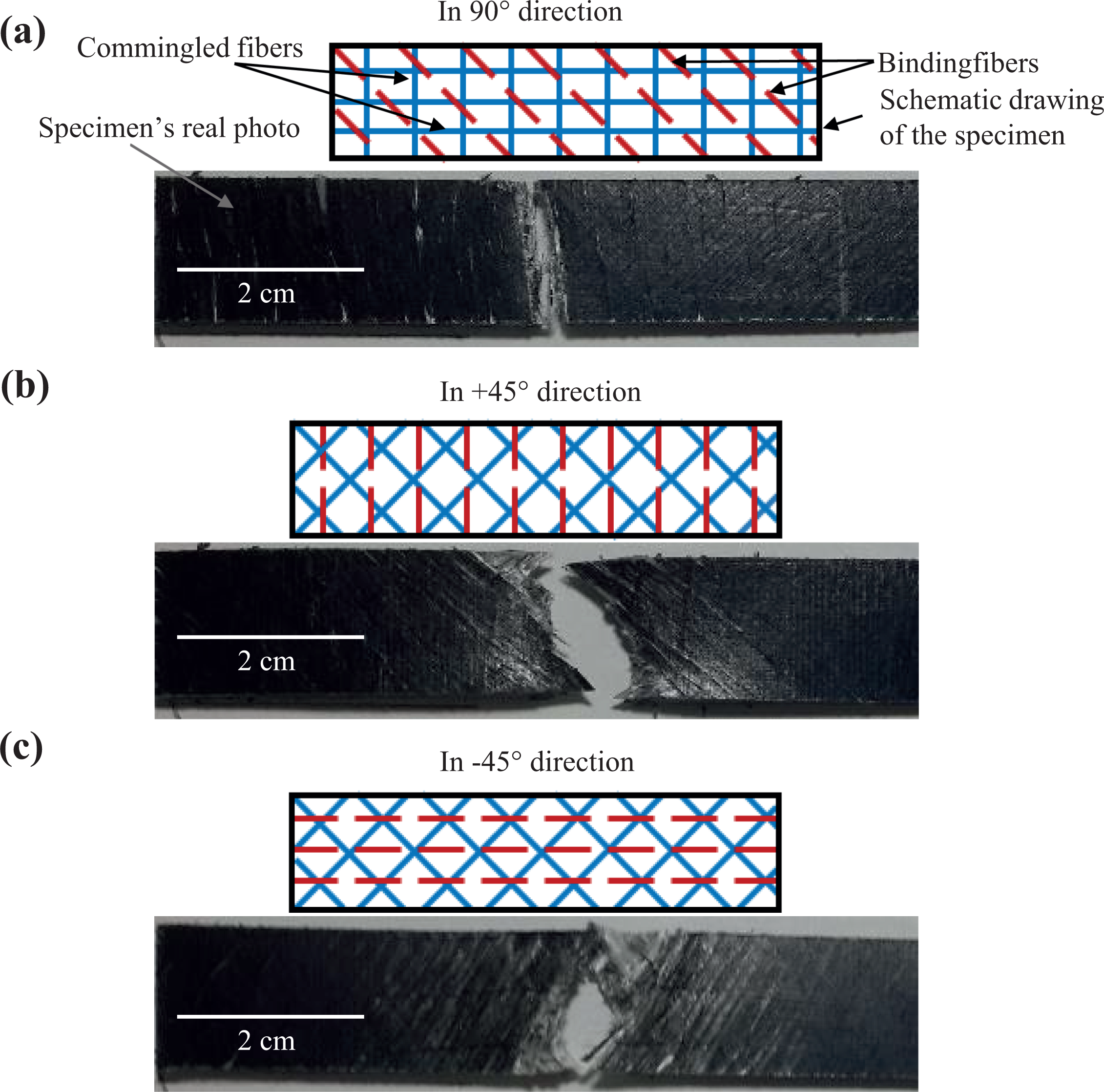
Fracture aspects after the three-point flexural test of the specimens with 0.7-wt% MWCNTs in (a) 90°, (b) +45°, and (c) −45° directions.
Figure 12(a) and (b) shows the fracture aspects of optical micrograph from bending tested specimens in 90° direction. The failure modes of both composite specimens were fiber breaks, matrix cracks, bucklings, and transverse cracks in tension and compression sides of the specimens. Figure 12(a) shows the cross section of neat composite specimen (0.0-wt% MWCNTs) after the breakage under flexural load. The delaminations were observed in the fractographic analysis in Figure 12(a). Figure 12(b) exhibits the cross section of composite specimen with 0.9-wt% MWCNTs. The delaminations weren’t observed in the fractographic analysis in Figure 12(b). The absence of delamination in 0.9-wt% MWCNTs specimen indicates superior interfacial bonding between GFs and LPET matrix due to the coating of fabric surface by MWCNTs solution. Our results of fractured specimens agreed well with the results of Zanjani et al. 39 who investigated manufacturing of high-performance epoxy matrix composites with CF/selectively integrated graphene as multi-scale reinforcements.
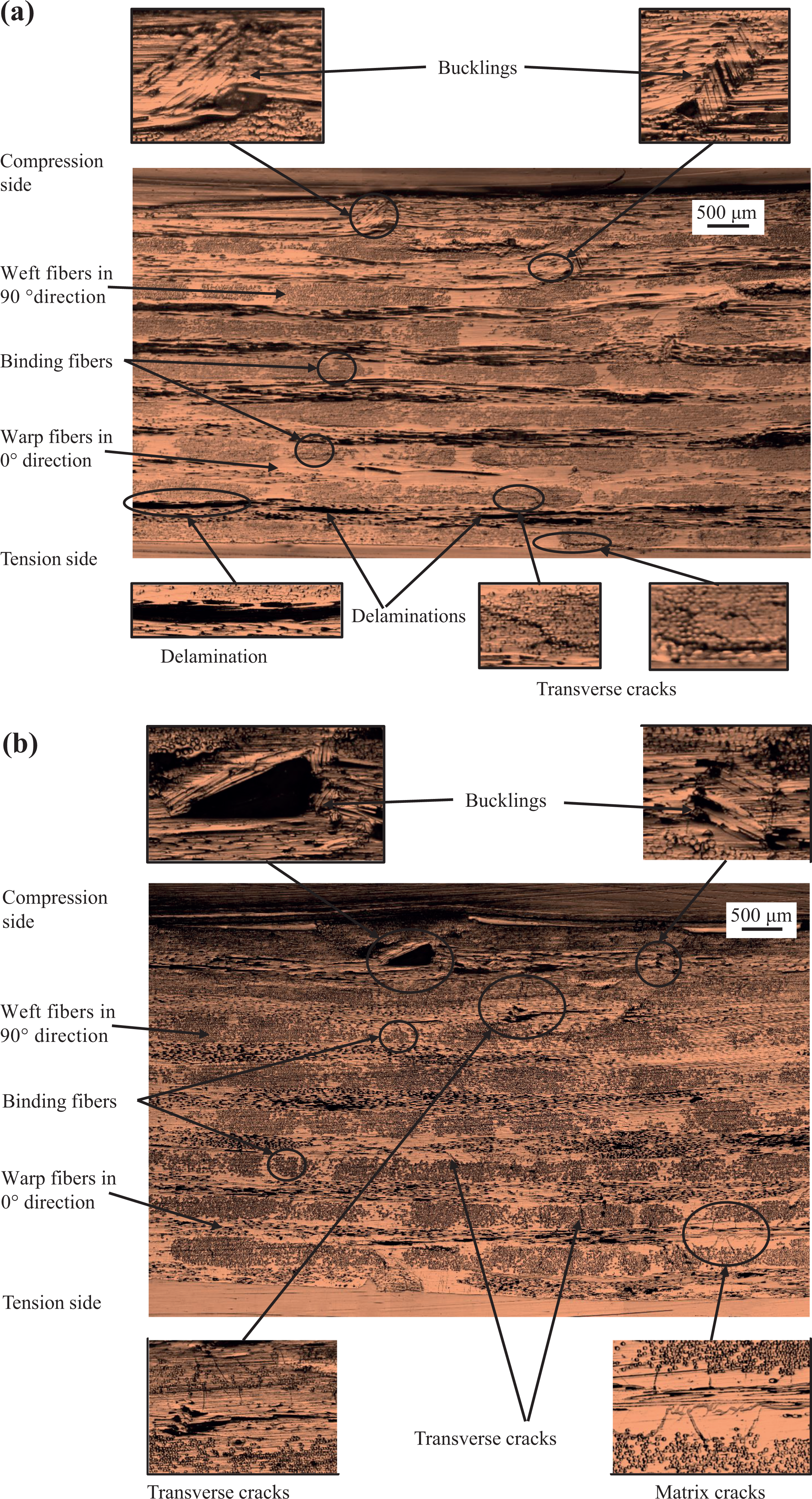
Fracture aspects of optical micrograph from bending tested specimens (a) 0.0-wt% MWCNTs and (b) 0.9-wt% MWCNTs.
Figure 13(a) and (b) shows the SEM images of fractured specimens with 0.9-wt% MWCNTs from bending test. Due to complex morphology of the fracture surfaces for CNTs-modified laminated composites, it is believed that several toughening mechanisms contribute to fracture toughness simultaneously such as polymer crazing, fiber bridging, CNT pullout, and crack branching. The polymer crazing mechanism occurs with the extensive yielding of the polymer matrix such as “stiches” between the new faces created by crack growth (Figure 13(a)). 31 These stiches may contain well-aligned CNTs inside and sword-in-sheath mechanism may aid as a toughening mechanism due to covalent interactions between the outer walls of CNTs and the polymer matrix, as shown in Figure 13(b). 40 It is observed that the polymer crazing mechanism occurs in all types of CNT-modified samples.
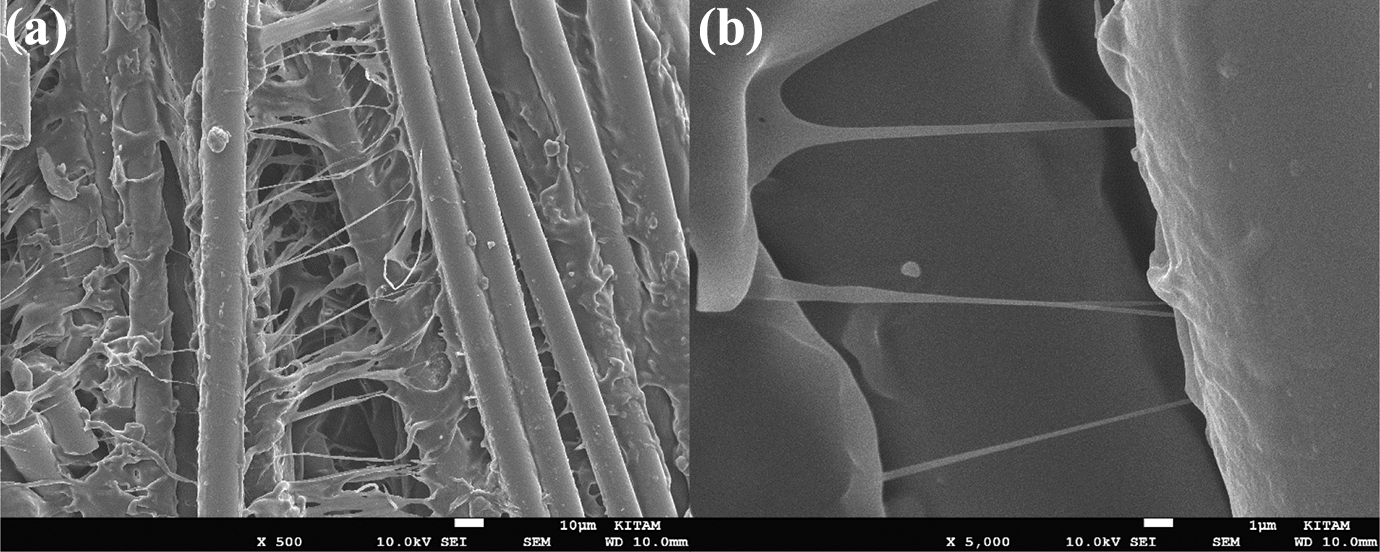
SEM images of fractured specimens with MWCNTs from bending test.
The good agreement between the results from the tensile and three-point flexural tests validated our test results.
Conclusion
Our study revealed that the tensile and three-point flexural properties of the thermoplastic composites with LPET/GF commingled yarns could be improved by incorporating different weight percentages of the MWCNTs at the interface of fabric layers.
The specimens with 0.9-wt% MWCNTs showed the best results in terms of the tensile modulus and strength, flexural modulus and strength among the other weight percentages of the MWCNTs such as 0.0, 0.7, and 1.1 wt% in +45°, 90°, and −45° directions. Experimental results showed that specimens with 0.9-wt% MWCNTs in 90° direction had the highest values of tensile and flexural properties with an improvement of about 8% and 33% in tensile and flexural modulus and about 3% and 65% in tensile and flexural strength compared to specimens without MWCNTs in 90° direction due to created synergy of nanotubes between fiber and matrix.
In future work, we will study the impact properties of the NCF–reinforced thermoplastic composites with various weight percentages of the MWCNTs.