
Abstract
The article presents the results of experimental and finite element analyses of the flexural vibration behavior sandwich composite with different debonding ratios. Sandwich composite consists of two thin skins composed of E-glass fiber and epoxy resin bonded to lightweight and weaker core material of PVC foams. Experimental tests using the impulse technique were performed on the sandwich constituents and sandwich composites with different debonding lengths. The modal dynamic characteristics of sandwich composite were measured and discussed for each debonding ratio. A finite element modeling was used to determine the natural frequencies, modal shapes, and stress and strain fields for each element of sandwich composites for each debonding ratio. The modal strain energy approach was used to determine the contribution of energies dissipated of the core and the skins in the total dissipated energy and the global damping of the different sandwich composites. The results obtained by this approach are compared with those obtained experimentally.
Introduction
Sandwich composite is constituted of skins and core, and these two parts are bonded using some adhesive. The skin material is thin, stiff, and strong, while the core material is thick, lightweight, and weaker. The sandwich composite is used in all industrial sectors including marine, aeronautics, aerospace, sports, civil engineering, and military because of their high specific stiffness and strength to weight ratios. However, the sandwich composite can be damaged during its use and manufacture. 1 –5 The presence of damage such as debonding and indentation can severely degrade the vibration properties of sandwich composite.
In the flexural, the debonding between the skin and the core of sandwich composite is one of the modes of damage. 6 Idriss et al. 7,8 studied the effect of damage on the linear and nonlinear vibration parameters. They concluded that the nonlinear parameter is more sensible of damage than the linear parameter. Burlayenko and Sadowsk 9 investigated experimentally and numerically (finite element method) the influence of size, location, and number of debonding on the natural frequency. Baba and Thoppul 10 showed that the natural frequency is influenced by the curvature angle and debonding length of composite sandwich. Paolozzi and Peroni 11 analyzed experimentally and by finite elements the effect of the position and size of debonding on the vibration behavior. The authors showed that there is a correlation between the position, size of debonding, and the higher vibration modes. Kim and Hwang 12 used the analytical model to determine the natural frequency of sandwich composite with debonding. The beam with debonding was divided into three regions: two regions without debonding and one region with debonding. In each region was applied the beam theory. Then they compared the frequency obtained theoretically and experimentally. Tracy and Pardoen 13 found that the delamination of laminated composite affect more even modes than odd modes. Shu and Della 14 analyzed analytically the influence of multiple delamination on the natural frequency of laminated composite. The beam is divided into several regions interconnected. The flexion–traction coupling is taken into account in this model. The results obtained from this analysis are in good agreement with the results of the literature. Idriss et al. 15 studied the fatigue behavior of sandwich composite with debonding. They found that the maximum load, the dissipated energies, and the loss factor damping change with the size of debonding. Triantafillou and Gibson 16 analyzed the influence of variable debonding length on the shear strength of sandwich composite. They showed that the shear strength was not affected by the small debonding length. Zenkert 17 showed that debonding at the median plane of the core reduces the resistance of the sandwich.
Saravanos and Hopkins 18 found that for the large delamination length of composite laminates, friction between the surfaces becomes very important. Suzuki et al. 19 proposed the finite element analysis of the damping of composite laminates with delamination. The modal strain energy method is implemented into this finite element analysis. The results obtained showed that this analysis describes fairly well the experimental results. Assarar et al. 20 used the energy approach to determine the loss factor of sandwich composite. El Mahi et al. 21 used the same approach for determining the damping for different composite laminates.
The purpose of the present article is to analyze experimentally and by finite element the effects of debonding ratio on the dynamic characteristics of sandwich composite. Experimentally, the modal flexural dynamic characteristics are determined for each debonding ratio using the impulse technique. Finite element analysis is used to evaluate the loss factor damping by the energy approach. The results obtained experimentally and by finite element were compared.
Materials and experimental procedure
Materials
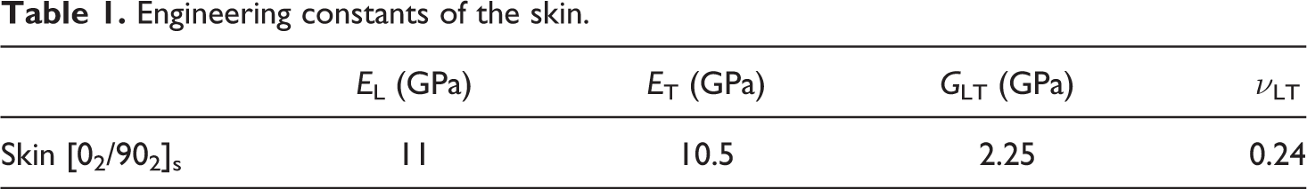
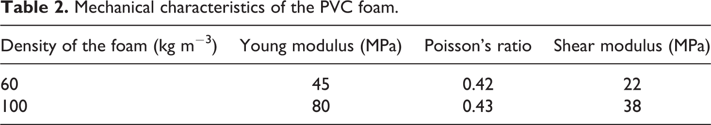
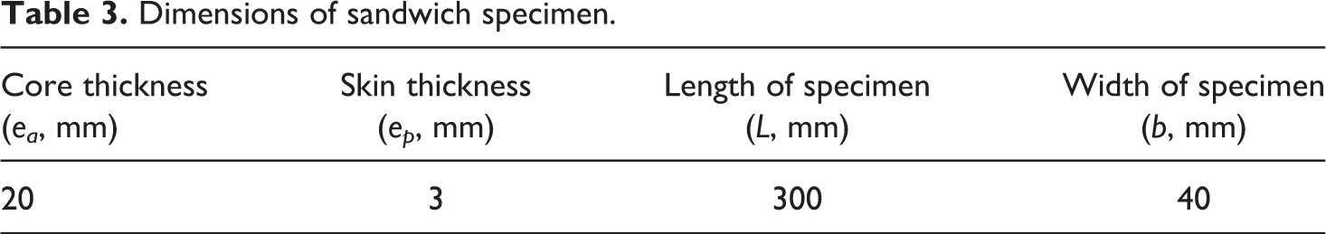
Sandwich composites studied in our work were constructed with E-glass fiber laminates as skins and with PVC foams as core. The laminates of the skins constituted E-glass fiber-reinforced epoxy resin and were manufactured with unidirectional layers, arranged in the sequence [02/902]s. Sandwich and laminates materials were prepared by hand layup process. The different plates were cured at room temperature (20°C) with pressure using a vacuum molding process. The mechanical characteristics in the Table 1 measured using tensile tests on unidirectional ply with the directions of 0°, 45°, and 90°. The transverse, longitudinal, and shear modulus of the unidirectional ply were used to define the transverse, longitudinal, and shear modulus of the skins. The Poisson’s ratio of the skins was considered equal to the matrix. The core is the PVC closed-cell foam with different densities and with thickness of 20 mm. The values of mechanical characteristics of the foam are presented in Table 2. The dimensions of the specimens are given in Table 3.
Engineering constants of the skin.
Mechanical characteristics of the PVC foam.
Dimensions of sandwich specimen.
Experimental procedure
The experimental equipment to study the vibrations of the specimen is shown in Figure 1. The specimen is supported horizontally as a cantilever beam in a clamping block. The specimen is excited near the clamping block with impulse hammer and the response of specimen is detected at another point near the free end of the specimen using a laser vibrometer. This vibrometer consists of an OFV 302 R optical head associated with an OFV 3000 controller. The excitation and output signals are digitalized and processed by a dynamic signal analyzer. This analyzer consists of an acquisition and processing card, associated with resident software for monitoring and signal processing. The system performs the acquisition of signals, controls the acquisition conditions (sensitivity, bandwidth, trigger conditions, etc.), and performs signal processing (Fourier transform, frequency response, etc.). The signals and associated processing can then be saved for post-processing. The experimental analysis was carried out in the case of bending of beams. The natural frequencies of the specimens are deduced from the Fourier transform of the beam response to an impulse excitation.
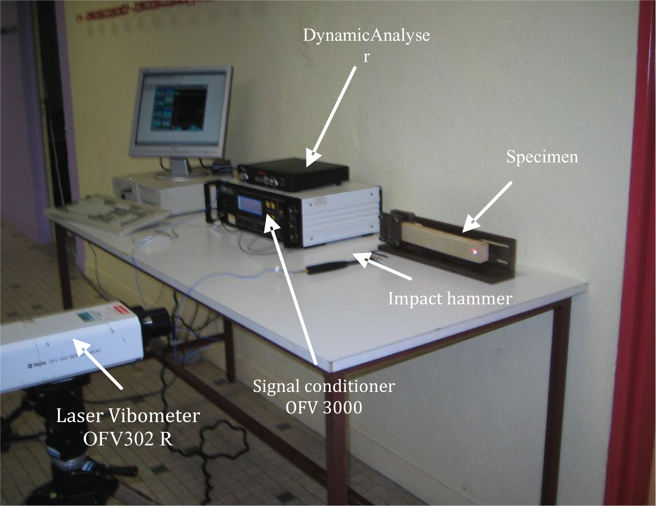
Experimental equipment.
Experimental investigation of constituent sandwich composite
Dynamic characteristics of the skins
The dynamic characteristics of skin specimens with lengths 230, 250, and 270 mm were measured. The values of dynamic characteristics are obtained by fitting the frequency response. This fitting is determined by the least square method.
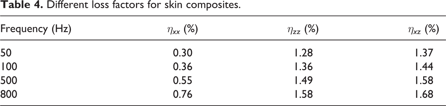
The loss factor was evaluated in three orientations (0°, 45°, and 90°) for the unidirectional fiber laminate and cross-ply laminate. The values of
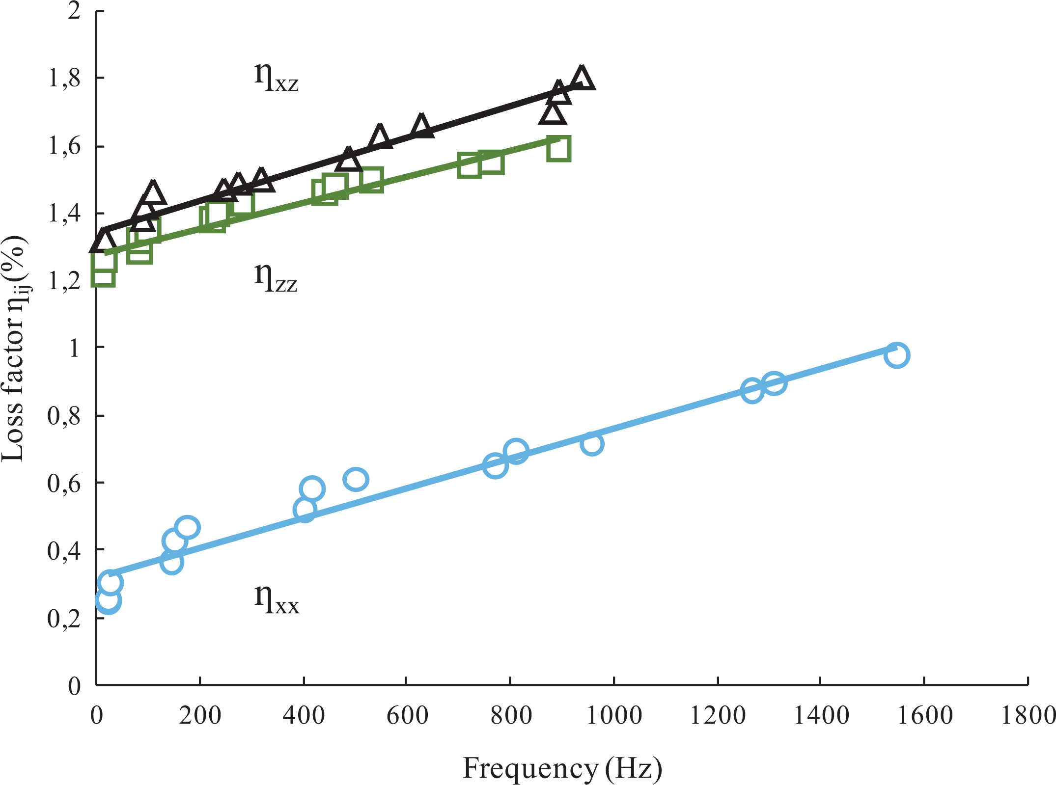
Different loss factors as a function of the frequency for skin composites.
Different loss factors for skin composites.
Dynamic characteristics of the core
In the case of viscoelastic materials, the dynamic characteristics depend on the frequency and are generally determined from ASTM E 756. 25 The dynamic characteristics of viscoelastic material were determined from the flexural vibration of a clamped-free beam. The specimen is constituted by two layers of aluminum beams with foam material interleaved between the two aluminum beams.
In our work, we used this technique to evaluate the damping of foams. Different types of beam were fabricated under vacuum in the laboratory. They are made of PVC foams for the core and aluminum skins with a thickness of 4 mm. They are differentiated by the density of the core (60 and 100 kg m−3). The foam cores were cut in the form of beams with width equal to 40 mm and for different lengths equal to 230, 250, and 270 mm. The two layers of aluminum were cut to the same dimensions as the cores. The foam core and aluminum skins are bonded together with the epoxy resin.
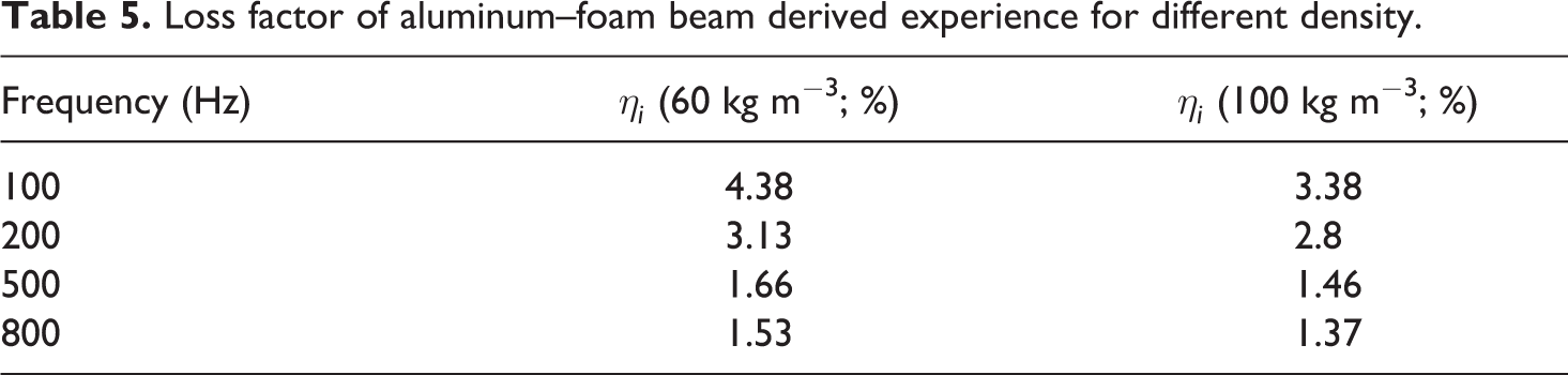
The experimental study was carried out from flexural vibration of a clamped-free beam (Figure 3). In the clamped part of the beam, the foam was replaced by a steel block so as not to crush the foam during tightening of the specimen. The frequency response of beam shows the peaks corresponding to the natural frequencies of the vibrations of the beam. The values of the natural frequencies and the modal damping coefficient or the loss factor of each mode are obtained by fitting the frequency response using the least square method. The variation of the loss factor as a function of the frequency obtained for the foam–aluminum test specimens for the two densities of foam is shown in Figure 4. We observe a decrease of the loss factor as a function of the frequency, with a rapid decrease in low frequency, the loss factor becomes practically constant for high frequencies for the two foams. We also observe that when the density of the foam increases, the loss factor decreases. This behavior is attributed to the size of the closed cells containing air, constituting the foam. 26 The loss factor values deducted from the experimental analysis for several frequencies are given in Table 5.
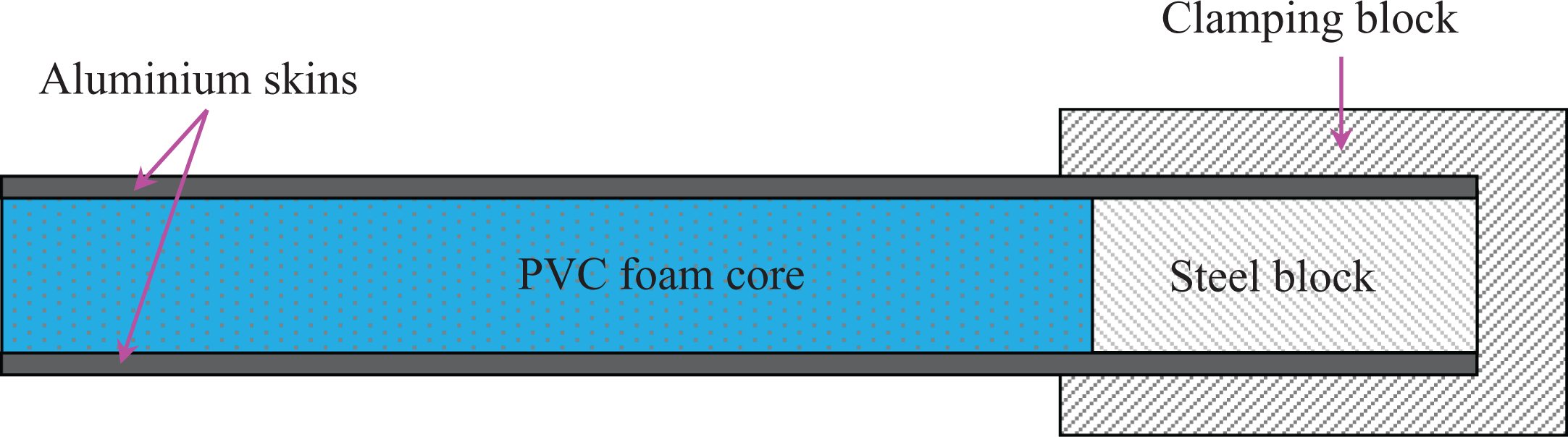
Aluminum–foam beam.
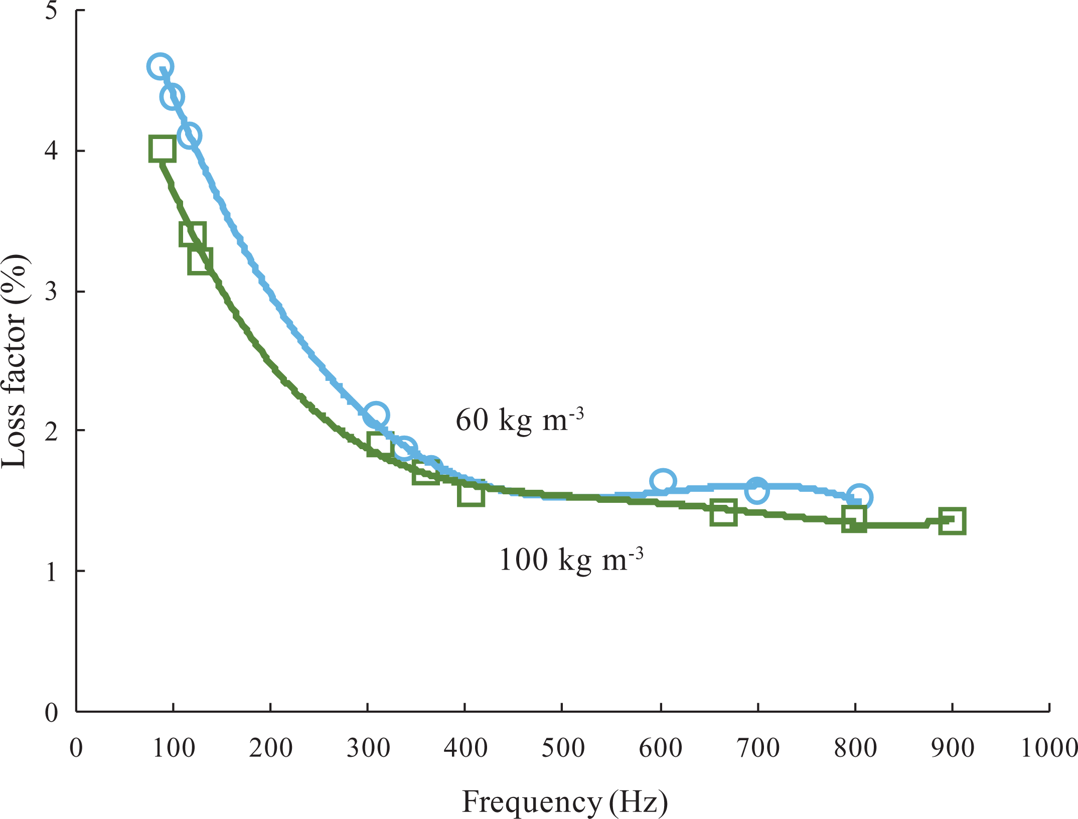
Loss factor derived experiment of aluminum-foam beam as a function of the frequency for two densities foam (60 kg m−3 and 100 kg m−3).
Loss factor of aluminum–foam beam derived experience for different density.
Finite element analysis
Modeling
The finite element analysis is used to evaluate the modal frequencies, the stress and strain fields in each element of the sandwich composite constituents. The sandwich composite is modeled by three structures, two anisotropic structures corresponding to skins arranged in the sequence [02/902]s and an isotropic structure representing the PVC foam core. The finite element modeling was created with ABAQUS (version 6.10). The continuum plane stress element (CPS4) is used for mesh. The element used is an element with four nodes based on the theory of plane stress. The debonding is between the skin and the core of sandwich beam, and it is modeled as a void between the skin and the core. The void has a low thickness. The debonding is increased by step to 20 mm until 180 mm. For each debonding ratio, we increase the number of mesh elements. The debonding surfaces are not in contact and the debonding length is constant during oscillations. The influence of friction is negligible in the modeling.
Strain energy
Stress and strain fields for a given mode of vibration in the elements of the skins (p) and in the core (a) for a finite element (e) are calculated by ABAQUS. The strain energy stored
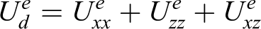
with
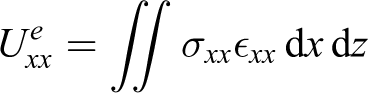
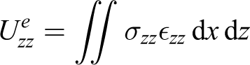

where the integrals are extended to the whole of the surface of a finite element e.

The total strain energy stored in the structure (Us) can take the form

with
Energies dissipated and global damping of sandwich structure
The evaluation of damping deducted from the finite element analysis can be approached by an energy approach. The energy dissipated in an element e of the skins or core of the sandwich composite is evaluated from the strain energy stored by introducing the damping coefficients along the different directions of the various elements constituting the sandwich material. The relationship is given by

with i = p, a; p and a are the skins and the core.
The damping coefficients are evaluated in the axes (L, T, T′) of the material (skin or core).
The energy dissipated in the skins is obtained by summation on all elements of the skins
The energy dissipated in the core is obtained by summing over all the elements of the core
The total energy dissipated is obtained by summing over all the elements of the sandwich composite beam

Finally, the global damping for the sandwich composite can be obtained by
Effect of debonding ratio
Natural frequencies
Many static studies showed that when the debonding length between the skin and the core of the sandwich composite increases, the shear stress transfer area between the skins and the core decreases. This decrease of transfer area causes a decrease in the strength and stiffness of the sandwich composite.
The dynamic characteristics of sandwich composite are investigated for each debonding ratio using flexural vibration and finite element modeling. The debonding is initiated between the core and the skin, and the progression is every 20 mm (Figure 5). For each mode and debonding ratio, the frequency is determined experimentally and by finite element analysis. The analysis of the experimental curves is allowed to obtain the values of modal frequency and modal loss factor for each debonding ratio. As shown in Figures 6
to 8, the influence of debonding ratio on the values of the natural frequency is witnessed from the evolution of the natural frequency as a function of the ratio of debonding for the first three modes of vibration and for the two sandwich composites (60 and 100 kg m−3). Experimental and finite element results are compared. The debonding ratio is defined as the ratio of the length of the debonding to the length of the free part of the specimen. The finite element analysis has been carried out taking into account the variation of mechanical characteristics of the core as a function of the frequency. Analysis of the results obtained shows that: Overall, the frequency decreases when the debonding ratio increases. This decrease is due to the degradation of the stiffness of the sandwich material which is the direct consequence of the decrease in the transfer area of the load between the skin and the core. The results obtained experimentally and by the finite element are in good agreement up to a limit value of debonding ratio.
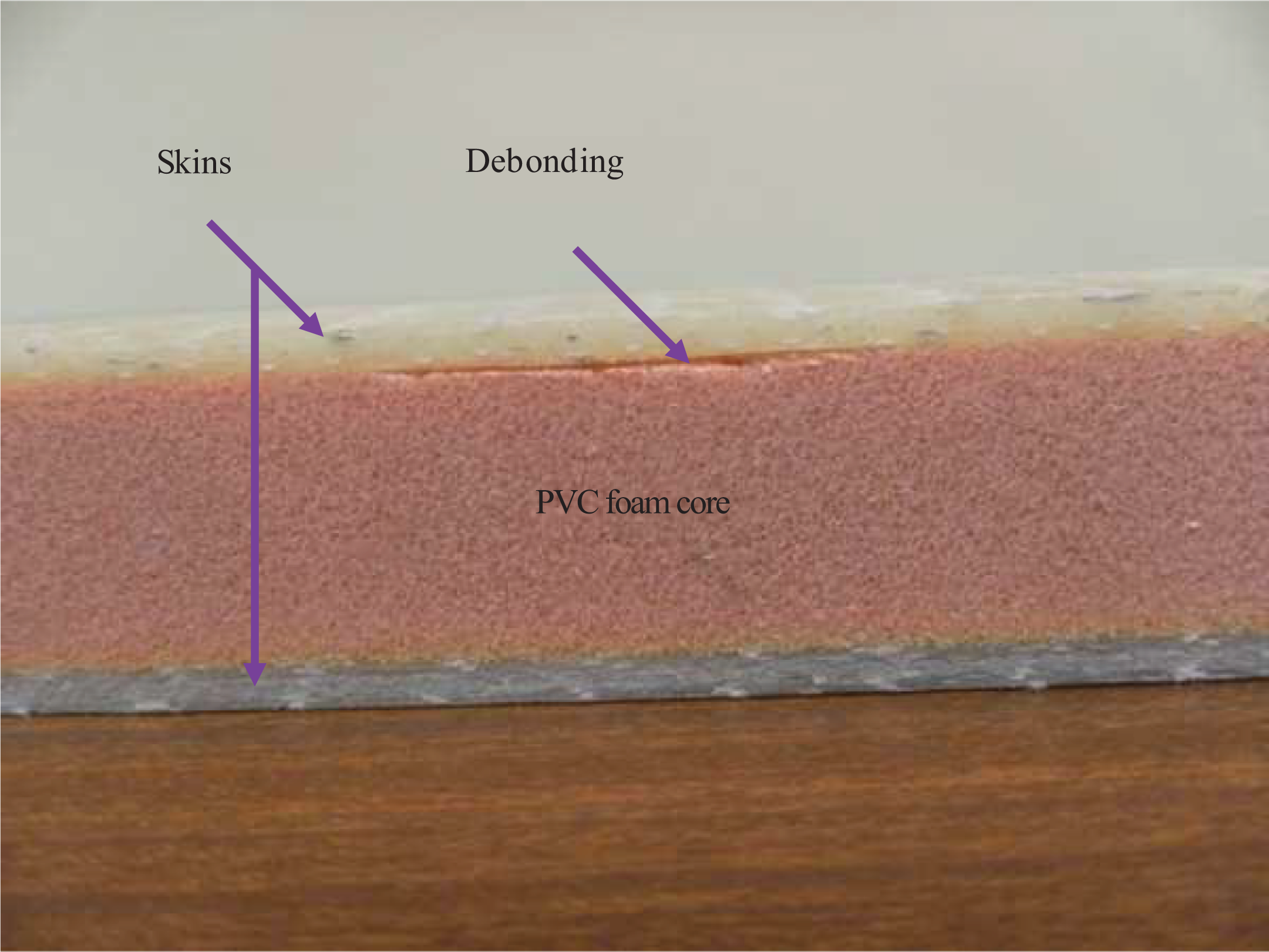
Sandwich composite beam with debonding.
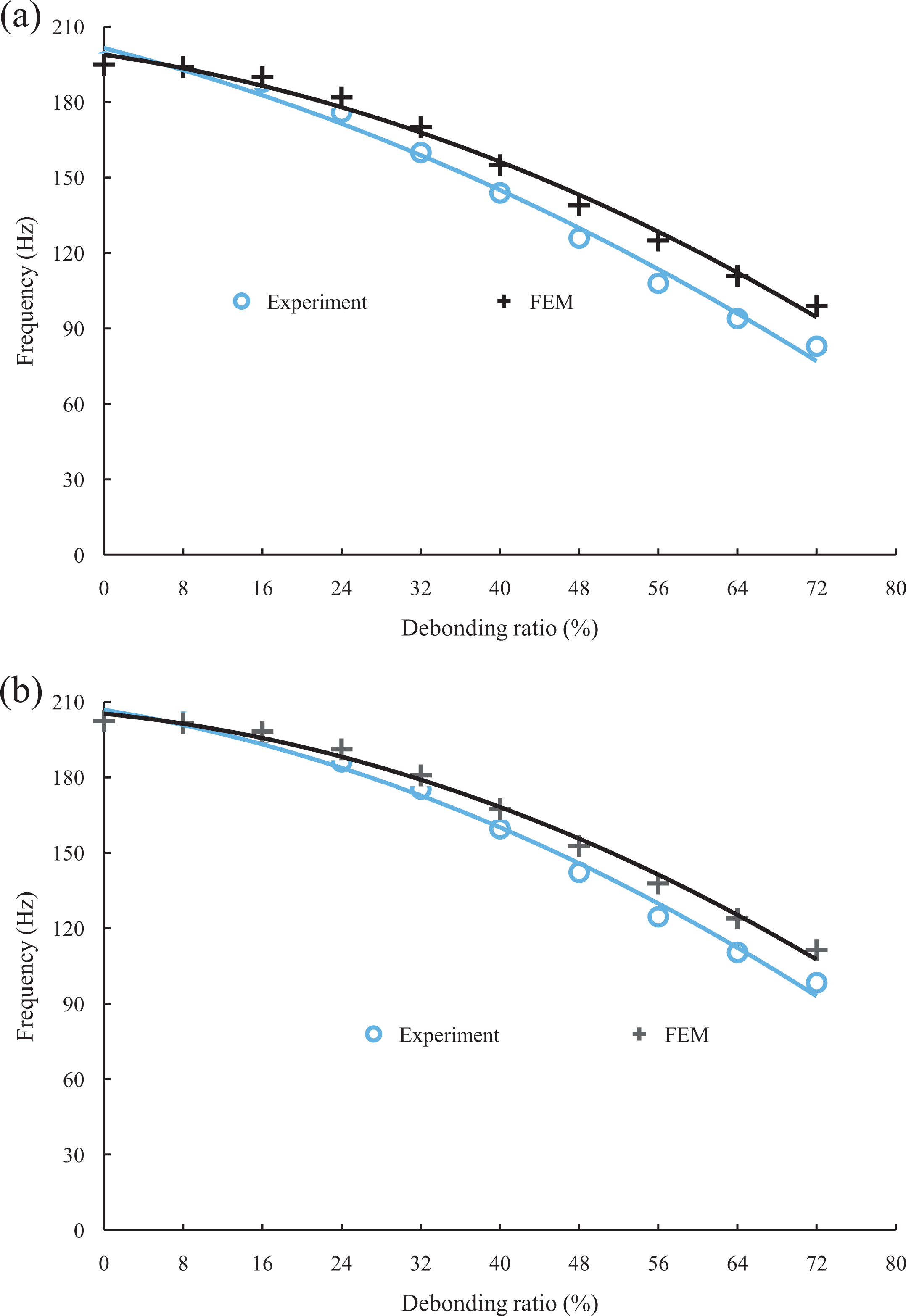
Comparison between the frequencies derived experiment and finite element modeling as a function of the debonding ratio in the case of the first mode for sandwich composite with foam density: (a) 60 kg m−3 and (b) 100 kg m−3.
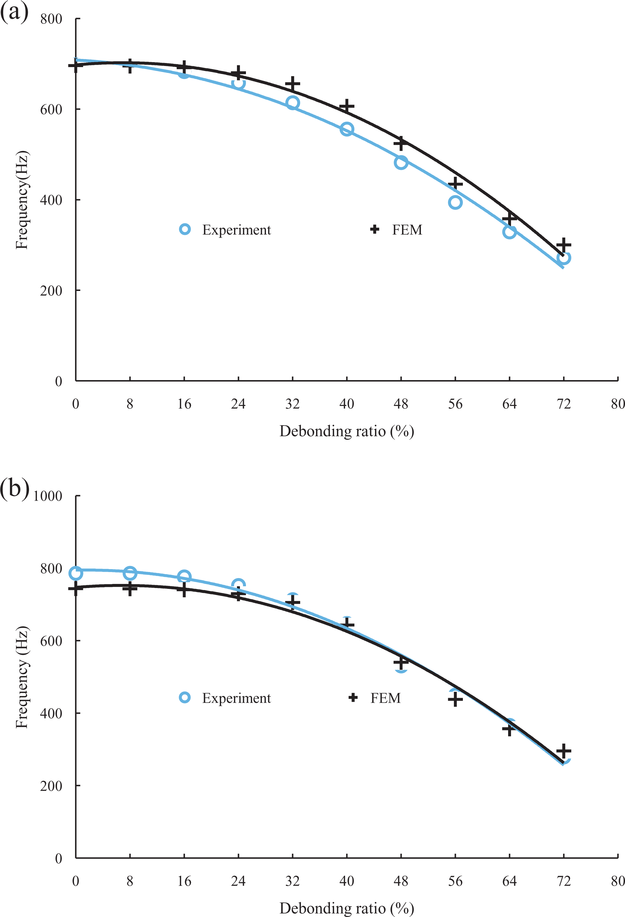
Comparison between the frequencies derived experiment and finite element modeling as function of the debonding ratio in the case of the second mode for sandwich composite with foam density: (a) 60 kg m−3 and (b) 100 kg m−3.
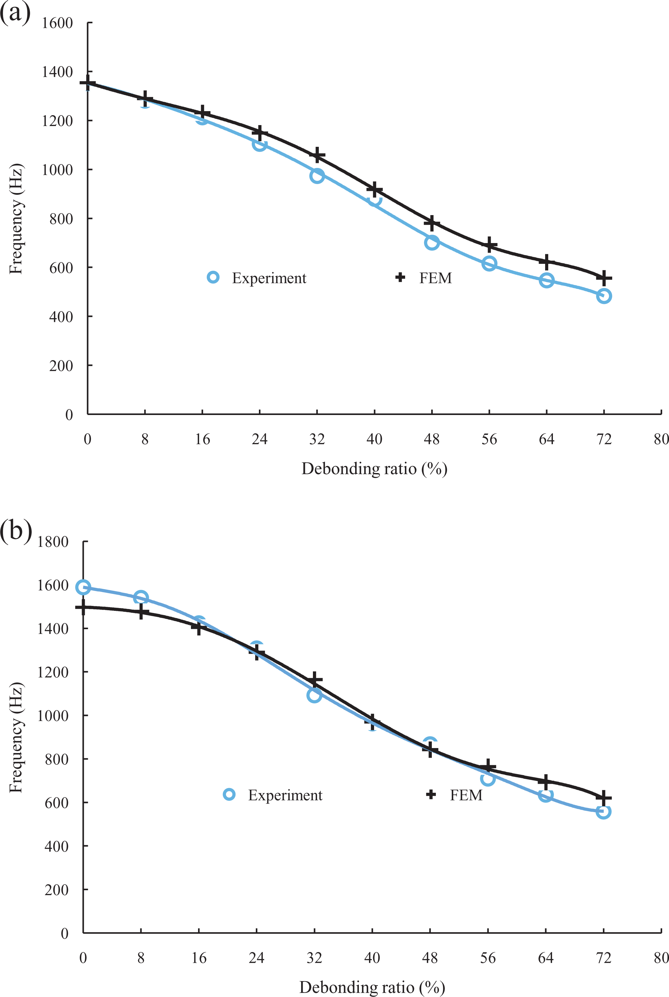
Comparison between the frequency-derived experiment and finite element modeling as a function of debonding ratio in the case of the third mode for sandwich composite with density foam: (a) 60 kg m−3 and (b) 100 kg m−3.
If we consider the values of frequency obtained by the experimental procedure and by the finite element in the case of the sandwich composite with 60 kg m−3 of foam density (Figures 6(a), 7(a) and 8(a)), the frequency is 196 Hz in the first mode for the undamaged sandwich composite, while it is only 83 Hz in the sandwich composite with 72% of debonding ratio. In the third mode, the frequency is 1350 Hz in the case of an undamaged sandwich composite, while the value is 480 Hz in the case of the sandwich composite with 72% of debonding ratio. The difference between experimental and finite element values does not exceed 4% with a smaller debonding ratio, while this difference can reach 16% for higher debonding ratio. This difference can be attributed to the contact and friction effects at the debonding surfaces, which were not taken into account by the finite element modeling.
For example, Figure 9 compares the modal shapes of the first three modes of vibration obtained by finite element modeling in the case of specimens without debonding (Figure 10(a)) and with 40% of debonding ratio (Figure 9(b)). We observe that the difference between the modal shapes of the undamaged specimens (Figure 9(a)) and the damaged one (Figure 9(b)) are clearly observable. Figure 9(b) shows an opening of the debonding in modes 2 and 3. This effect is more remarkable for mode 3.
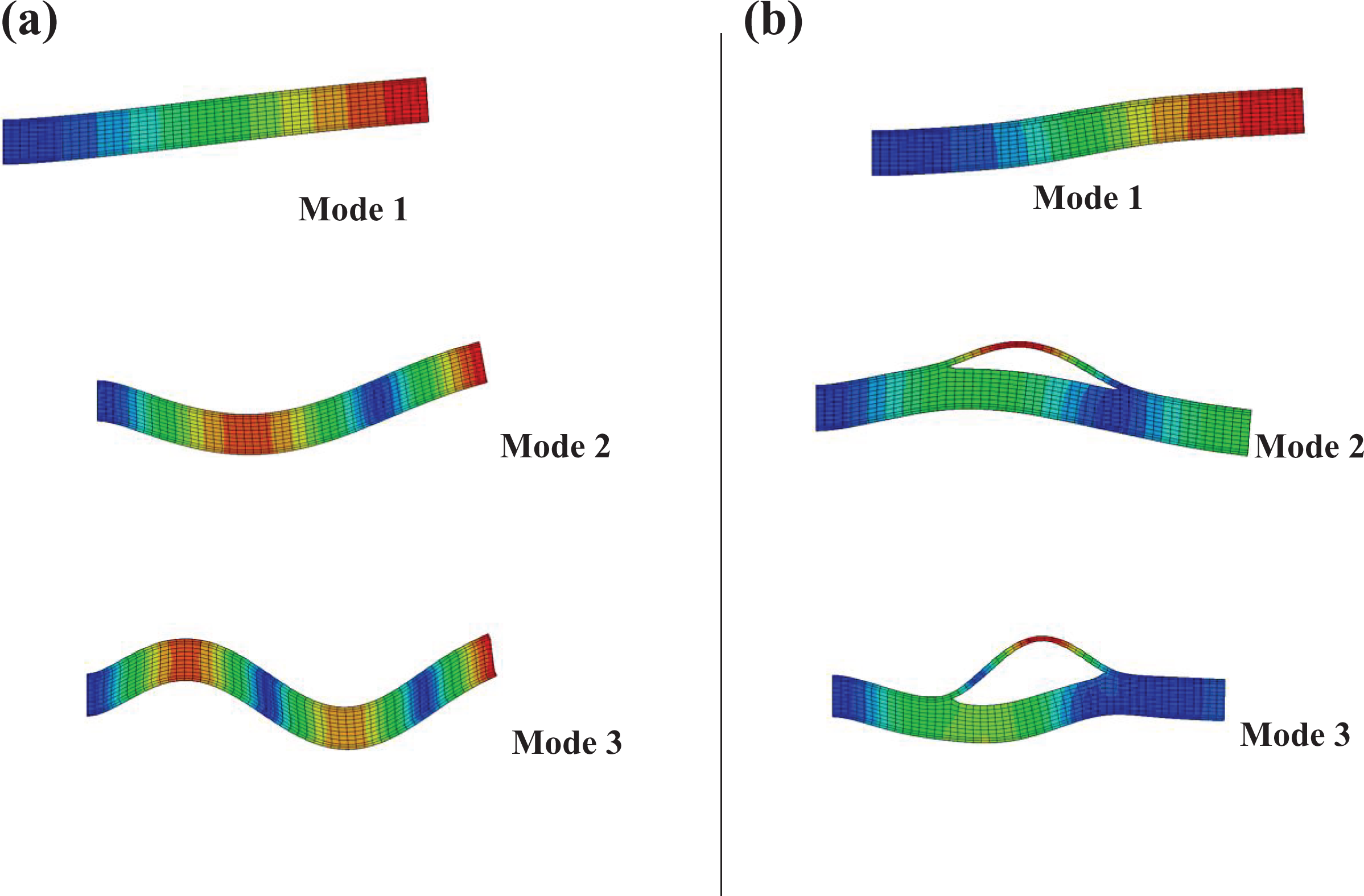
Examples of shapes of the three first modes of vibration in the case of sandwich composite with 60 kg m−3 of foam density for specimen: (a) undamaged, (b) 40% of the damage value.
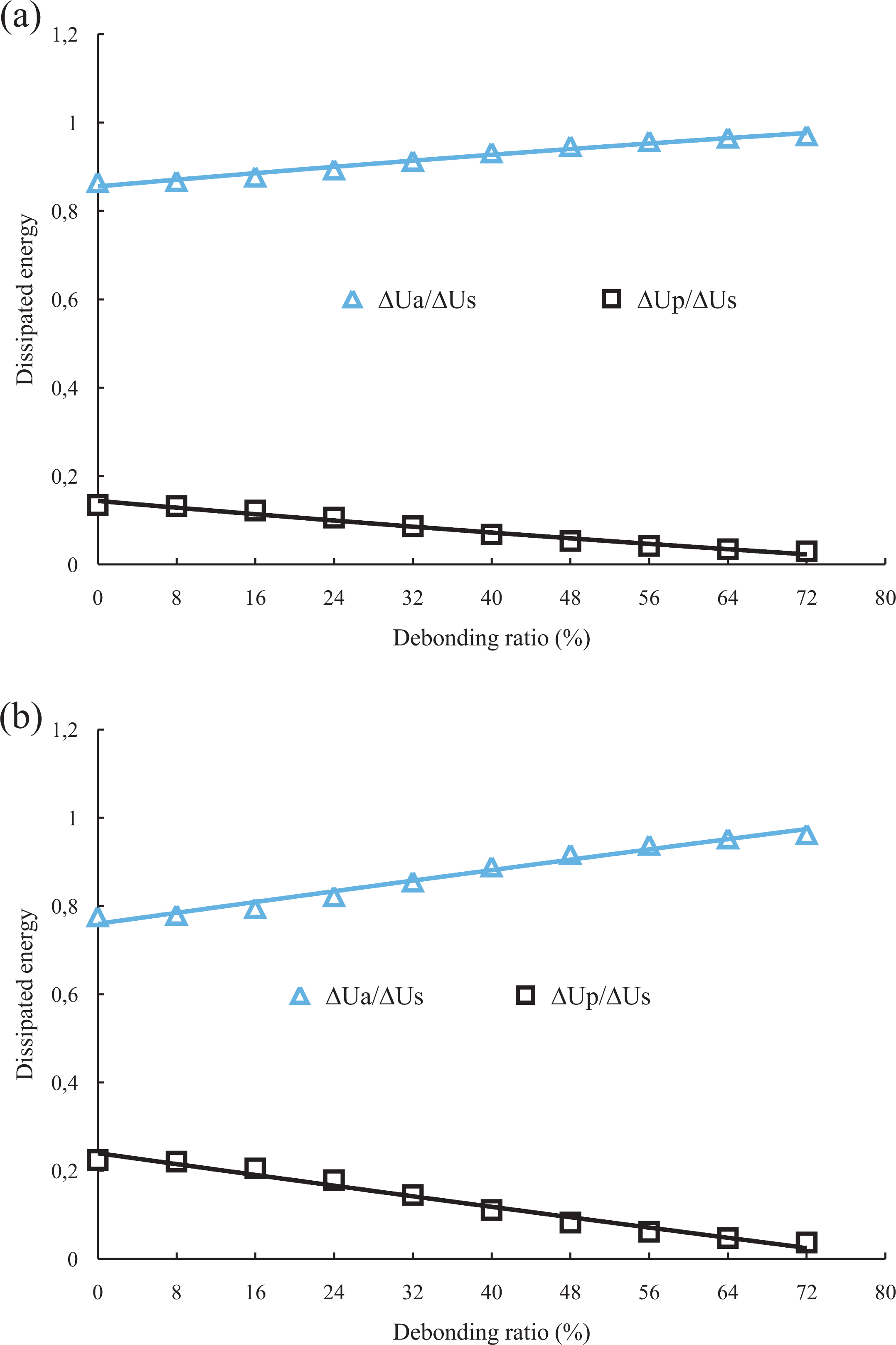
Energies dissipated in the core and skins as a function of the debonding ratio in the case of the first mode for sandwich composite with foam density: (a) 60 kg m−3 and (b) 100 kg m−3.
Energies dissipated
For example, Figure 10 shows the contribution of energies dissipated of the core and the skins in the total dissipated energy. In this figure the evolution of the energies dissipated in the core and in the skins is plotted as a function of the debonding ratio in the case of foam cores of density 60 and 100 kg m−3. These results were obtained by finite element modeling for the first mode of vibration. The energy dissipated in the core increases when the debonding ratio increases, while the energy dissipated in the skins decreases. The energy dissipated in the core of 100 kg m−3 of density is slightly greater than that of energy dissipated in the core of 60 kg m−3. For the two foam cores of density 60 and 100 kg m−3, the energy dissipated in the foam core is higher than the energy dissipated in the skins. For higher debonding ratio, the loss factor of the sandwich material is governed by the dynamic behavior of the core.
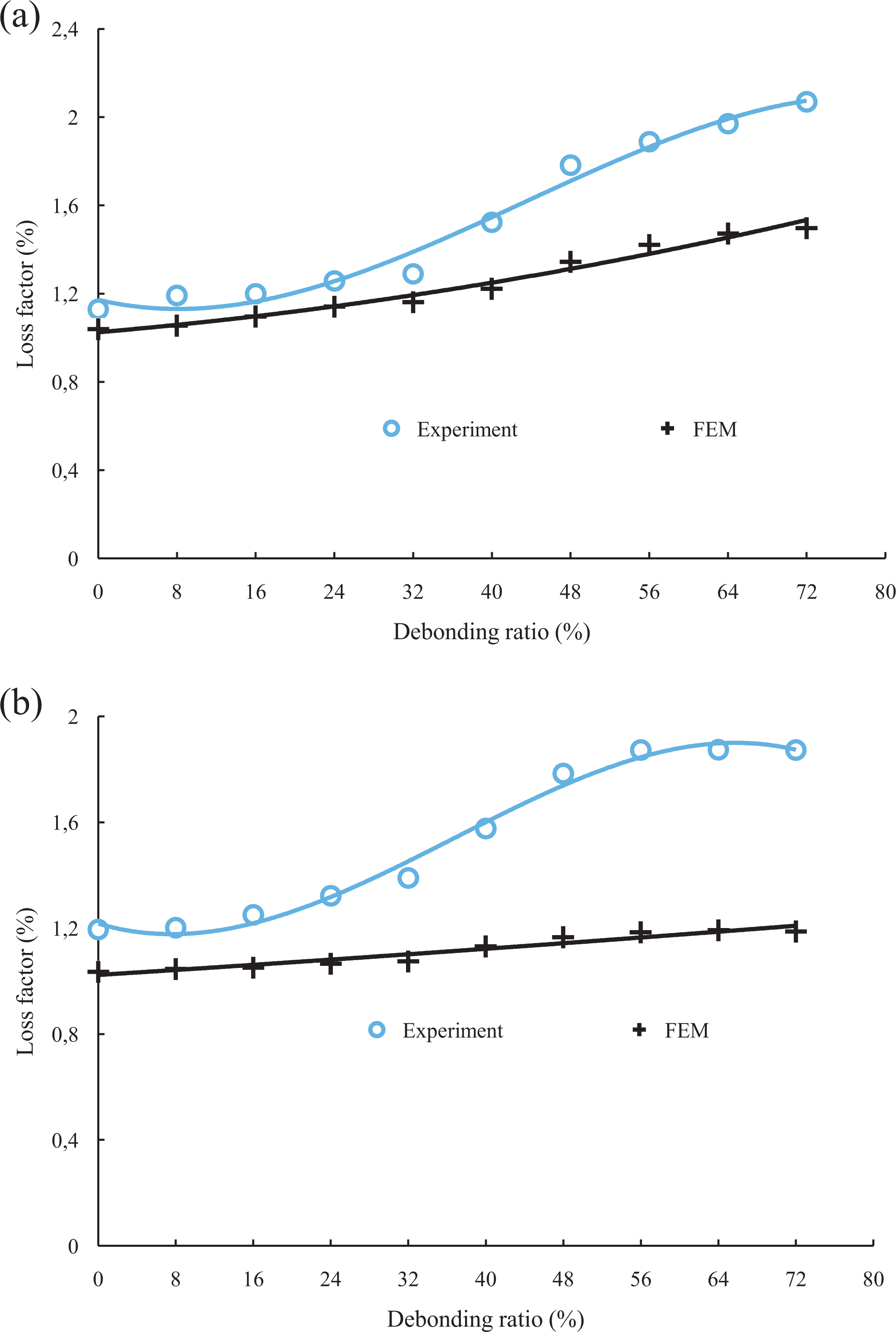
Loss factor
The finite element modeling takes into account the variation of the damping as a function of the frequency of different constituents of the sandwich composite (skins and core). Figures 11
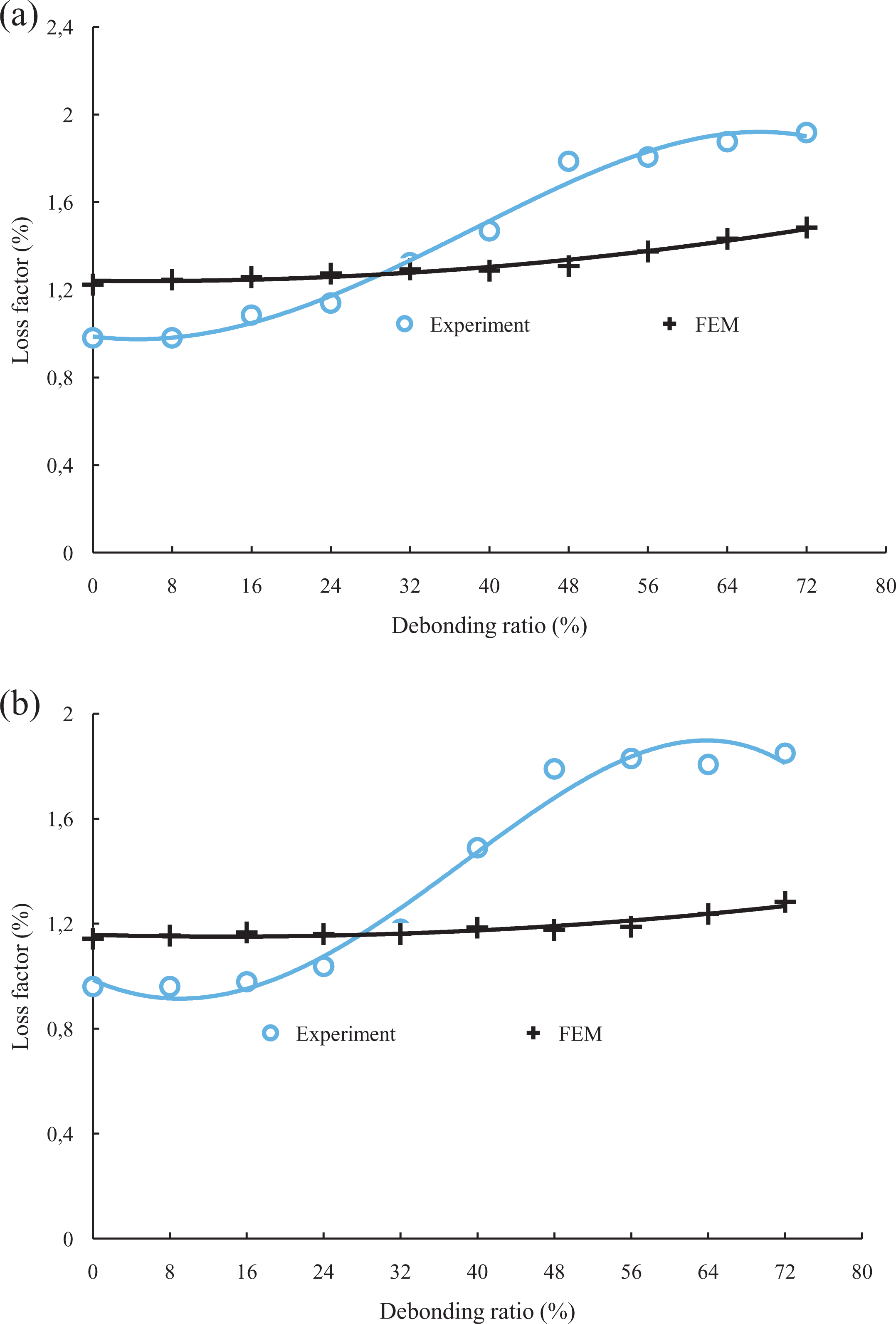
to 13 compare the results obtained by the experimental analysis and finite element modeling for the two sandwich composites and for the first three modes of vibration. Analysis of the results obtained shows that Overall, for a given mode, the loss factor increases with the increase of the debonding ratio, the authors
27
–31
also showed that the damage in the sandwich composite increased the loss factor damping. The damping obtained experimentally in modes 2 and 3 shows a very significant variation in the range 30–50% of debonding ratio, and the difference becomes important with the results of the finite element modeling. The difference between the results obtained by finite elements and the experimental analysis can be attributed to the phenomena of contact and friction between the surfaces of debonding. It has been shown in the study of Yang et al.
32
that contact and friction have a significant influence on the value of damping. The evolution of damping of the sandwich materials as a function of the length of debonding depends on several parameters: the distribution of the strain energy between the skins and the core and the variation of the damping in the skins and core as a function of the frequency (Figures 2
and 4).
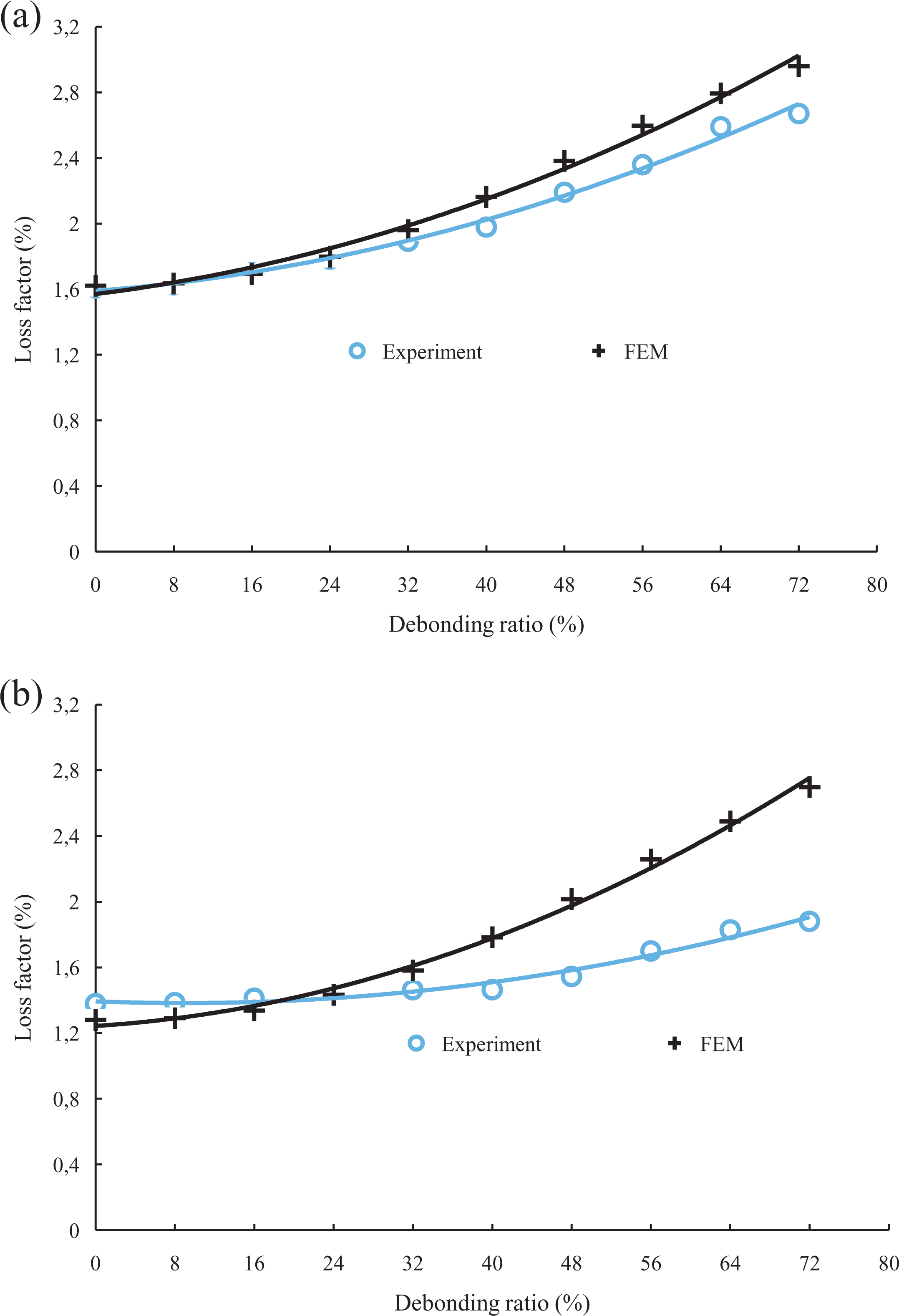
Comparison between the loss factor-derived experiment and finite element modeling as a function of debonding ratio for the first mode in the case of sandwich composite with foam density: (a) 60 kg m−3 and (b) 100 kg m−3.
Comparison between the loss factor-derived experiment and finite element modeling as a function of debonding ratio for the second mode in the case of sandwich composite with foam density: (a) 60 kg m−3 and (b) 100 kg m−3.
Comparison between the loss factor-derived experiment and finite element modeling as a function of debonding ratio for the third mode in the case of sandwich composite with foam density: (a) 60 kg m−3 and (b) 100 kg m−3.
Conclusions
The experimental analysis of the dynamic behavior of the sandwich composites and their constituents was carried out in the case of beam flexural vibration. Response to an impulse was established, resonance frequencies and damping were deduced from the tests by fitting the experimental response using the least square method. Finite element modeling used to identify the dynamic properties of sandwich materials in the presence of debonding from the strain energies of the constituents. The natural frequencies obtained experimentally and those of the finite elements are in good agreement up to a limit value of debonding ratio. The result showed that the natural frequencies decrease and the damping increases when the ratio of the debonding increases. A discrepancy between the experimental and finite element values appears for high values of debonding ratio. This difference could be explained by the variation of the mechanical properties of the sandwich composite and the sandwich constituents as a function of the frequency. It could be caused due to the effects of the contact and the friction of the debonding surfaces. Indeed, the finite element modeling implemented does not take these parameters into account. Nevertheless, this result showed a decrease of the natural frequencies and an increase of the energies dissipated when the debonding ratio increases. The decrease of frequencies and increase of the energies dissipated can be due to the problems of friction. 32