
Abstract
In this study, thermoelastic stress analysis in composite metal cylindrical vessel is investigated with the help of two theories, first-order shear deformation theory (FSDT) and layerwise theory, using differential quadrature method (DQM). Hamilton principle and FSDT are employed for derivation of the principle differential equations. DQM and Newmark’s methods are used for stress analysis of a composite metal cylindrical vessel subjected to internal dynamic pressure and thermal load achieved from experimental test. In order to more accurately estimate the thickness effect, the layerwise theory is applied to approximate the temperature field. In this solution method, DQM is used to discretize the resulted governing equations while Newmark’s method is implemented to solve the problem in the time domain. It was observed that the fast convergence rate of the DQM method and its accuracy is confirmed by comparing the results with those obtained using ABAQUS software and also with the exact solutions. Furthermore, it was achieved significantly less computational efforts of the proposed approaches with respect to the finite element method.
Keywords
Introduction
Composite materials are becoming an important part of engineering materials because they present advantages as higher specific stiffness and strength, improved corrosion resistance, and better fatigue strength compared to other materials. The best structures in different industries such as chemical, petroleum industries, and so on are thick-walled cylinders that are used as pressure vessel and cylindrical shells. In advanced industries, the application of new materials such as composite and functionally graded materials (FGM) are increasing due to their high usage in controlling stresses due to mechanical and thermal loads. Ordinary pressure vessels made of single layer may very often satisfy the service requirement subject to high temperature, high pressure, and corrosive environments. Therefore, a multilayer composite pressure vessel is widely used to meet the requirements under various industrial service condition by using different layers of different material. Generally, the inner layer is made of high performance alloy material because the inner layer is subjected to high pressure and high temperature while the outer layer is made of steel or fiber. In aerospace structures such as multilayer composite plates and shells, the temperature changes are one of the most important factor for the stress fields that cause their failure. Composite materials of high efficiency combine a number of properties, including high specific stiffness and strength, and nearly zero coefficient of thermal expansion in the direction of fiber. These properties result in a growing use of composite materials in structures under extreme thermal environment, such as high temperatures, high gradients, and temperature cycling changes. Due to these implications, considerable works on laminated shells under mechanical/thermal loading are as follows. Noor et al. 1 studied the effects of both mechanical loadings and high temperature have to be considered in the design process of such structures. Studies involving the thermoelastic behavior using classical or first-order theories are described by Kant et al. 2 Khdeir et al. 3 described the thermoelastic behavior using classical or first-order theories. Barut et al. 4 analyze the nonlinear thermoelastic behavior of shells by means of the Finite Element Method, but the assigned temperature profile is linear. Miller et al. 5 investigated thermal stress analysis of layered cylindrical shells. Dumir et al. 6 remarked the importance of the zigzag form of displacements in the thermal analysis of composite shells. Lee 7 studied the analysis of thermal stresses within multilayered cylinder under axial symmetry periodic boundary conditions. Ootao et al. 8 investigated an angle-ply laminated cylindrical panel with simply supported edges due to a nonuniform heat supply in the circumferential direction. Shahani et al. 9 solved transiented thermoelasticity problem in an isotropic thick-walled cylinder analytically using the finite Hankel transform. Talor and Radu 10 investigated the sinusoidal transient temperature for an isotropic hollow cylinder in an axis symmetric condition for the analyses of the thermal fatigue in the pipelines. Hocine 11 preformed on thermomechanical behavior of multilayer tubular composite in axis metric steady state conditions. His results express that thermal effect has the greatest influence on radial stresses and strains. Zamani Nejad et al. 12 presented a complete and consistent 3-D set of field equations by tensor analysis to characterize the behavior of FGM thick shells of revolution with arbitrary curvature and variable thickness along the meridional direction. Bakaiyan et al. 13 investigated the stress and deformation of the filament-wound pipes under combined internal pressure and temperature variations with axisymmetric and steady-state consideration. Kumar et al. 14 studied an extensive thermostructural analysis of composite structures, including temperature-dependent properties, mechanical, thermal, and thermochemical loads, and presented a coupled thermostructural analysis for a solid rocket motor nozzle with different orthotropic and isotropic materials. In the study by Yoo et al., 15 a kick motor nozzle incorporating spatially made from reinforced composites was subjected to thermoelastic analysis following the development of a material model used to homogenize various 3-D reinforcement architectures. Wang et al. 16 investigated the thermoelastic dynamic solution of a multilayered orthotropic hollow cylinder in the state of axisymmetric plane strain. Atefi et al. 17 presented an analytical solution for obtaining thermal stresses in a pipe caused by periodic time varying of temperature of medium fluid. Jabbari et al. 18 studied a general analysis of one-dimensional steady-state thermal stresses in a hollow thick cylinder made of functionally graded material. Shao et al. 19 presented thermomechanical analysis of functionally graded hollow cylinder subjected to axisymmetric mechanical and transient thermal loads. Kant 20,21 investigated a general theory for small deformations of a thick shell made up of a layered system of different orthotropic materials having planes of symmetry coincident with the orthogonal reference frame and subjected to mechanical and arbitrary temperature distribution. Khare et al. 22 presented a closed-form solution for the thermomechanical analysis of laminated orthotropic shells. Khdeir et al. 23,24 studied the thermoelastic governing equations for laminated shells that are exactly solved and then a higher shear deformation theory is given. They assume a linear or constant temperature profile through the thickness. Birsan 25 presented an interesting method to analyze the thermal stresses in cylindrical Cosserat elastic shells for two given temperature fields. Iesan 26 with assuming of polynomial temperature variation in the axial coordinate investigated thermal stresses in heterogeneous anisotropic Cosserat elastic cylinders. Barut et al. 27 studied nonlinear thermoelastic analysis of composite panels under nonuniform temperature distribution with linear temperature profile. Miller et al. 28 investigated thermal stress analysis of layered cylindrical shells. Dumir et al. 29 is noteworthy, they presented the importance of the zigzag form of displacements in the thermal analysis of composite shells. In the case of shells, further investigations were developed by Hsu et al. 30 for both Finite Element method and closed form and by Ding 31 for a weak formulation study for thick open laminated shell including the boundary conditions. The importance of thermoelasticity of cylindrically anisotropic generally laminated cylinders in such investigations was remarked by Padovan. 32 Some interesting experimental results in deformation analysis of thermally loaded composite tubes can be found in Holstein et al. 33 Carrera et al. 34 presented some results on thermal stress of layered plates and shells by using unified formulation. Cinefra et al. 35 investigated thermal stress analysis of laminated structures by a variable kinematic MITC9 shell element. Cheila et al. 36 investigated dynamic mechanical and thermal behavior analysis of composites based on polypropylene recycled with vegetal leaves. Cinefra et al. 37 presented heat conduction and thermal stress analysis of laminated composites by a variable kinematic MITC9 shell element. To the best of authors’ knowledge, there is no published paper on the thermoelastic analysis of laminated cylindrical shells by using the mixed layerwise and first-order shear deformation theories (FSDTs) with differential quadrature method (DQM). In this study, the thermoelastic behavior of laminated cylindrical shells subjected to internal dynamic pressure and thermal loading achieved from experimental test are investigated by DQM. In order to more accurately estimate the thickness effect, the layerwise theory is used to approximate the temperature field while FSDTs is used to estimate displacement field. DQM is implemented to discretize the resulted governing equations while Newmark’s method is applied to solve the problem in the time domain. The MATLAB programming code have been used to solve differential quadrature equations. The accuracy and convergence of the algorithm are proved via different references.
Thermal governing equations
Heat transfer formulation in composite cylindrical vessel
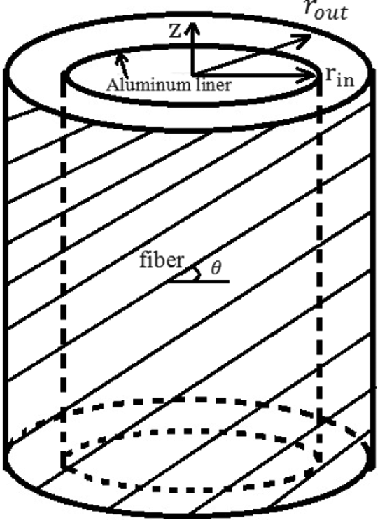
In this section, the basic concepts of heat transfer formulation in composite cylindrical vessel are presented briefly. Figure 1 shows the geometry of such composite cylinder.
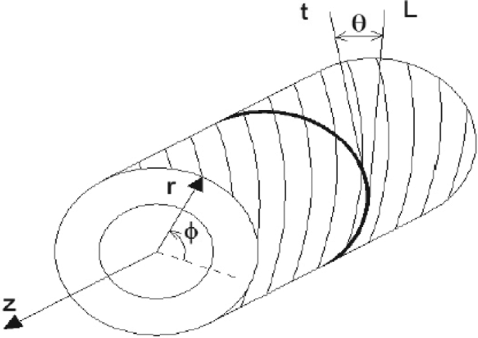
Direction of fibers in a cylindrical laminate.
In this figure, r, ∅, and z are elements of off-axis coordinate system (reference coordinate system). If L is tangent line on cylinder in direction of fibers and t is tangent line on cylinder in direction of ∅, hence; angle of fibers (θ) is angle between L and t. Axisymmetric unsteady heat transfer in longitudinal and radial directions (r, z) has been considered in this study. The fibers are wound around the cylinder and the direction of the fibers in each lamina can vary between layers. Fourier law for cylindrical multilayer composite laminate as shown schematically in Figure 1 system is given by 38
where q is heat flux,
where ρ and cp are density and specific heat capacity at constant pressure respectively and conductive heat coefficient (
In these relations, k11 is the conduction coefficient in parallel direction of fibers, and k22 is the conduction coefficient in perpendicular direction of fibers, m1 and n1 represent cos θ and sin θ, respectively. With substituting equation (3) in equation (2), the heat transfer equation in cylindrical composite laminate is obtained
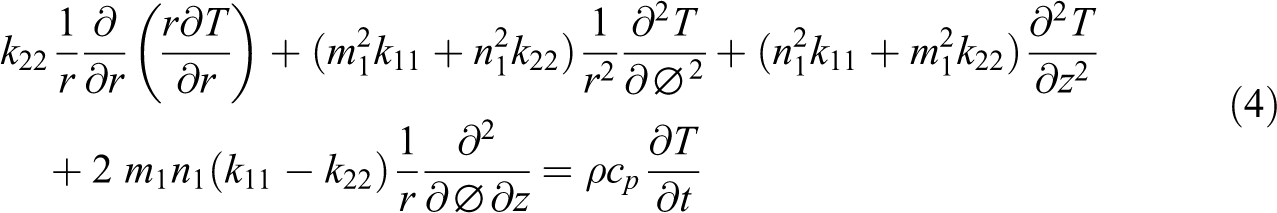
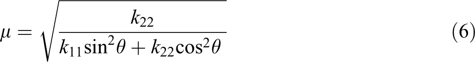
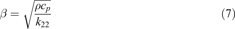
With the assumption of axisymmetric unsteady heat transfer in longitudinal and radial directions (r, z), equation (4) can be written in a different way according to equation (5)
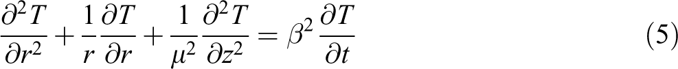
where
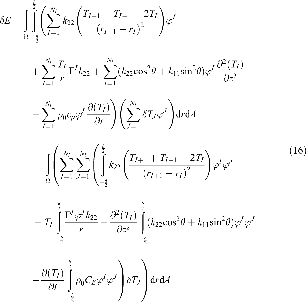
Thermal governing equations in layerwise theory
Figure 2 shows schematic temperature distributions in linear layerwise theory. The temperature field in the form of layerwise theory for axisymmetric cylindrical shells is as follows 42,43
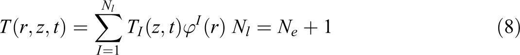
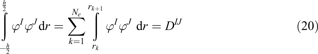
where Ne is the total number of mathematical layers, TI is the values of the temperature at the bottom of the Ith mathematical layer in the r- and z-direction, respectively, and φI is interpolation approximation functions or a continuous function in terms of the thickness coordinate r. Nl represents the number of nodes in the r-direction of the shell, which depends on the number of considered mathematical layers Ne through the thickness.
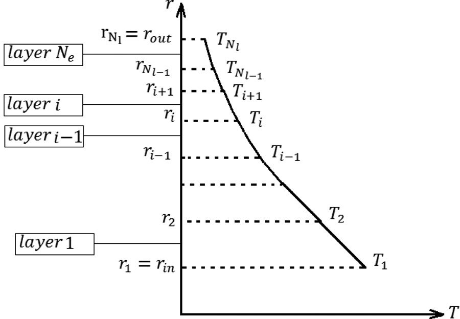
The through-thickness approximation of the temperature field.
By substituting equation (8) into equation (5) will be resulted in
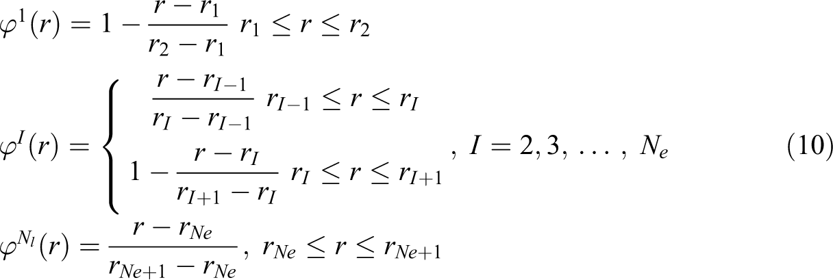
The global linear interpolation function in the ith mathematical layer is defined as below 44
Form the first derivative of interpolation functions are as follows
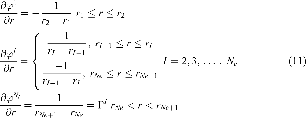
Second-order derivatives interpolation functions will be equal to zero. Therefore, to compensate, this problem has been assisting from finite difference method
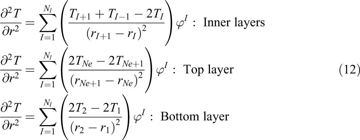
So, with the help of derivatives interpolation function (equations (11) to (12)) and equation (9) will be resulted in

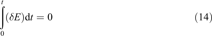
where Γ I is calculated from equation (11). The governing equations for the present layerwise theory can be derived using the variational principle 44 –48
where
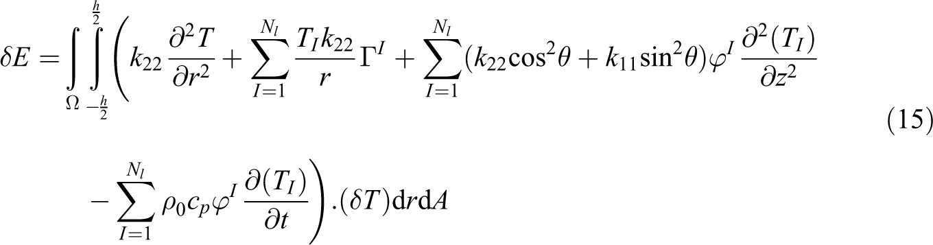
where h is thick laminated cylindrical shell. By substituting equations (12) and (8) into equation (15), obtain
Simplification of the above equation in equations (17) to (20) is expressed
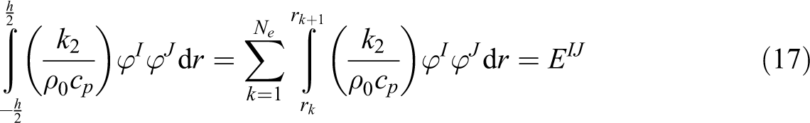
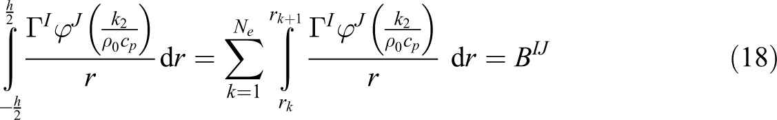
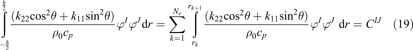
where Ne is number of layers of envisaged in layerwise theory. By substituting equations (17) to (20) into equation (16), obtain
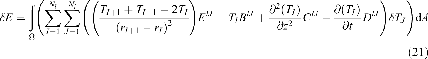
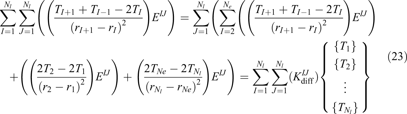
By substituting equation (21) into equation (14) and by using the Euler-Lagrange equations are derived temperature governing equations in laminated cylindrical shells with layerwise theory as follows
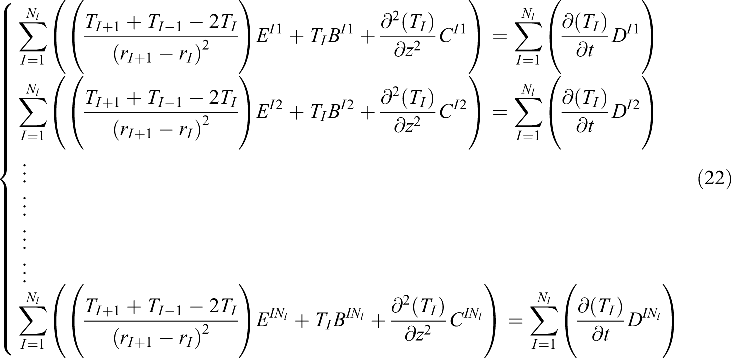
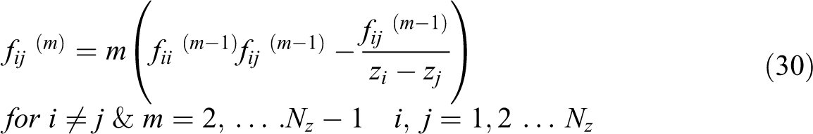
where Nl is the number of nodes in layerwise theory. For the integration of the second derivative term in the above equations due to the equation (12) can be used the following equation
where
DQM for thermal governing equations
At this stage, the governing differential equations are discretized into algebraic equations using DQM. In this method, the first- and second-order partial derivatives of a field variable at the ith discrete point in the computational domain are approximated by a weighted linear summation of the field variable at all discrete nodes located along the line that passes through that point in the domain. A differential quadrature approximation at the ith discrete point on a grid at the z-axis is given by 49,50


where
Higher order derivatives of the DQM can be obtained as follows
For variables r and t equations (24) to (31) exist that is omitted for brevity.
Newmark’s time integration method for thermal governing equations
As an alternative method and in order to obtain a comparative solution, Newmark’s time integration scheme is applied in the time domain to the DQM discretized form of the governing equations and the related boundaries. In this procedure, the dynamical system of equation (22) at time (t + Δt) is solved according to the equations (32) and (33) 44

where Δt is time step,
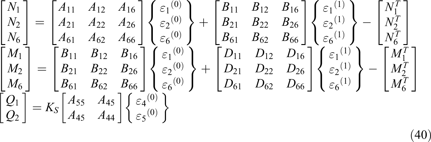
where [TI] is temperature in nodes;
where BJI, CJI, and DJI are obtained from equations (17) to (20);

Basic equations in fiber-reinforced composites under thermoelastic load
In the present study, FSDT is employed to simulate the deformation of every layer of the cylinder in terms of deformation of mid-surface and rotation about outward axis of the mid-surface. The temperature field is calculated from layerwise theory and to be put in thermoelastic equations of FSDT. A circular cylindrical shell with radius of R, thickness h, and the length l is shown in Figure 3. The u1, u2, and u3 are the displacement components in the axial, tangential, and radial directions, respectively, and that the deformations are assumed to be small. The displacement field of the first-order theory is of the form:
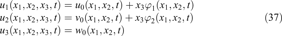
where (
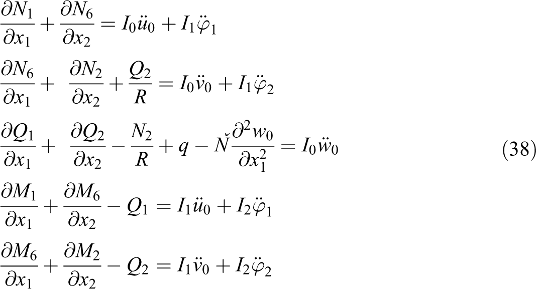
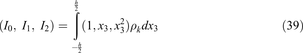
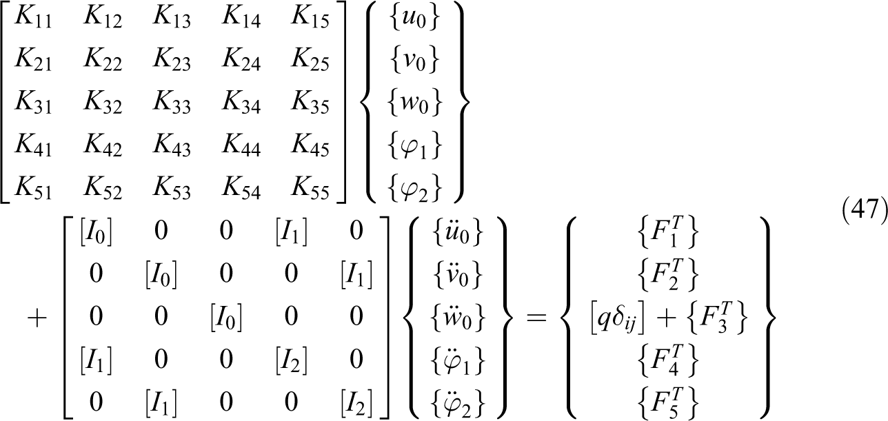
where Ň is the axial compressive load (positive in compression); I0, I1, and I2 are the mass inertias and are defined in equation (39);
where ρk is the density for each layer; KS is the shear correction factor introduced by Mindlin and is equal to
where ΔT = T − T0; T0 is the reference temperature;
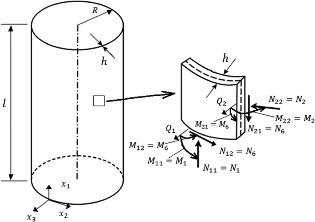
Laminated shell geometry in cylindrical coordinate system and stress resultants on a shell element.
At this stage, the governing differential equations are discretized into algebraic equations using DQM. Newmark’s time integration scheme is applied in the time domain to the DQM discretized form of the governing equations. DQM and Newmark’s method are presented in “Differential quadrature method for thermal governing equations” and “Newmark’s time integration method for thermal governing equations” sections for temperature field. In the following, this relationship is used for displacement field as follows
where aij, bij, cij, dij, and eij are the weighting coefficient matrices in DQM method;
where M and N are the number of elements in the x1- and x2-direction,
where
Results and discussions of numerical analysis
In order to test the accuracy and efficiency of the developed algorithm, here we present numerical results for a number of sample problems. Then, the convergence study and further analysis are performed.
Two-layer
angle-ply clamped cylindrical shell under internal pressure
The following geometric parameters and lamina material properties were used in the study
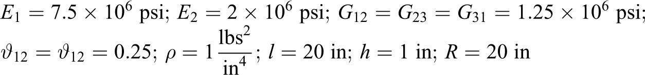
and subjected to an internal uniform step pulse (i.e. applied at time t = 0 and kept indefinitely) of intensity q0 = 5000 psi is considered. The results of the present study are compared in Figure 4 with those obtained by Reddy and Chandrashekhara. 52 The results have good agreement with the DQM solution. This shows the correctness and reliability of the present formulation.
Transient response of two-layer [−45°/45°] angle-ply clamped cylindrical shells under internal pressure (q0 = 5000 psi, Δt = 0.005 s).
Two-layer laminated cylindrical shell with heat transfer analysis
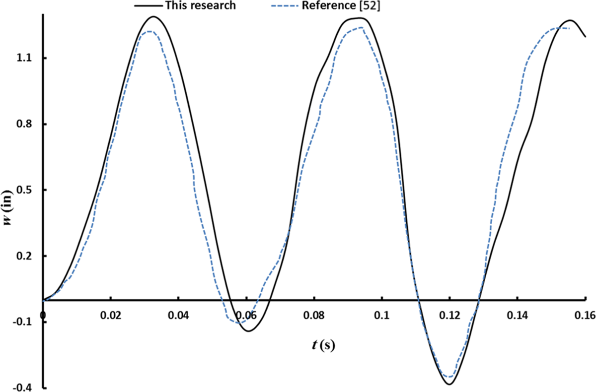
To validate heat transfer analysis in the present study (heat transfer analysis with layerwise theory), comparisons with the exact solution of references. 53,54 This example includes a two-layered cylinder with the following characteristics

The temperature distribution versus layers position in direction of cylinder radius is shown in Figure 5 at t = 0.1 for the number of nodes across the thickness is considered to be Nl= 2, 4, 8, 10, 12, and 14. It is seen that the temperature distribution converges already with 16 grid points through the thickness of the cylinder.
Temperature distribution in two-layered cylinder.
Laminated shell with metallic liner under thermoelastic load
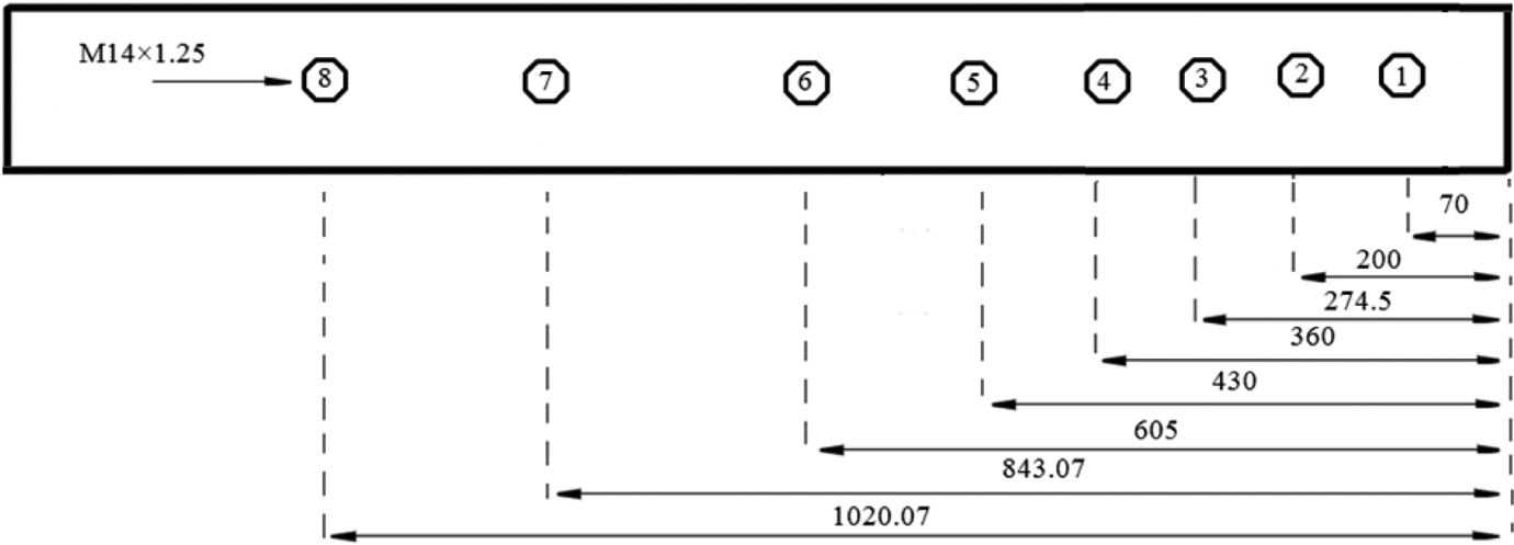
In this example, a sample of metal composite cylindrical vessel is considered. A schematic of the vessel is shown in Figure 6. The vessel consists of five layers. The first layer is aluminum that its properties are listed in Table 1. This layer with thickness of 2 mm is used for vessel liner. Four other layers are used from the composite T700 that their properties are listed in Table 2. Thickness and angles of composite layers are (1.5, 0.5, 0.5, 2) millimeters and (90, 75, 75, 90) degrees, respectively. This vessel is used to a specific user. The cylinder is subjected to internal dynamic pressure and thermal load. Dynamic pressure has been obtained from an experimental test. For this work has been considered a metallic vessel. Some points from the vessel have been punctured for installation of pressure sensor adaptors. Then, with reinforcing connector parts, welding has been performed upon the shell by argon weld. The vessel dimensions are listed in Table 3. For loading or create pressure in the vessel has been utilized 800 g double-base propellant.
Schematic of metal composite cylindrical vessel.
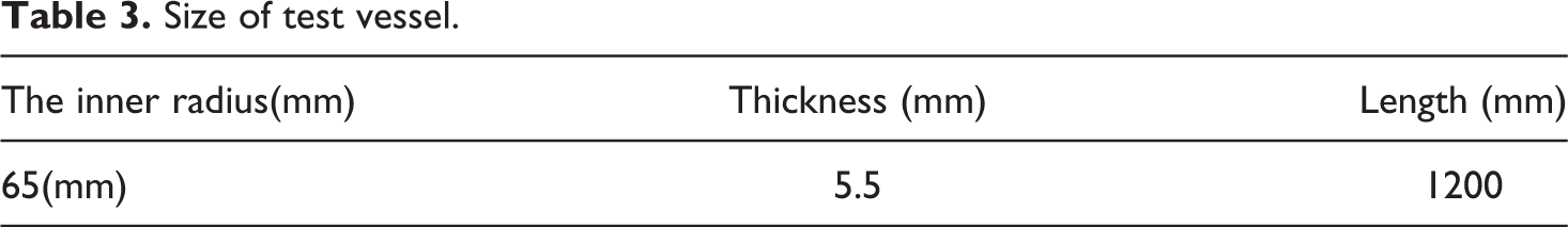
Size of test vessel.
The schematic arrangement of the sensors is shown in Figure 7. Piezoelectric sensors (kistler model 601H) have been utilized for dynamic pressure measurement. After preparation, experimental test was done that a sample of pressure–time diagram obtained from test results has been shown in Figure 8.
The schematic arrangement of the sensors (dimensions in mm).
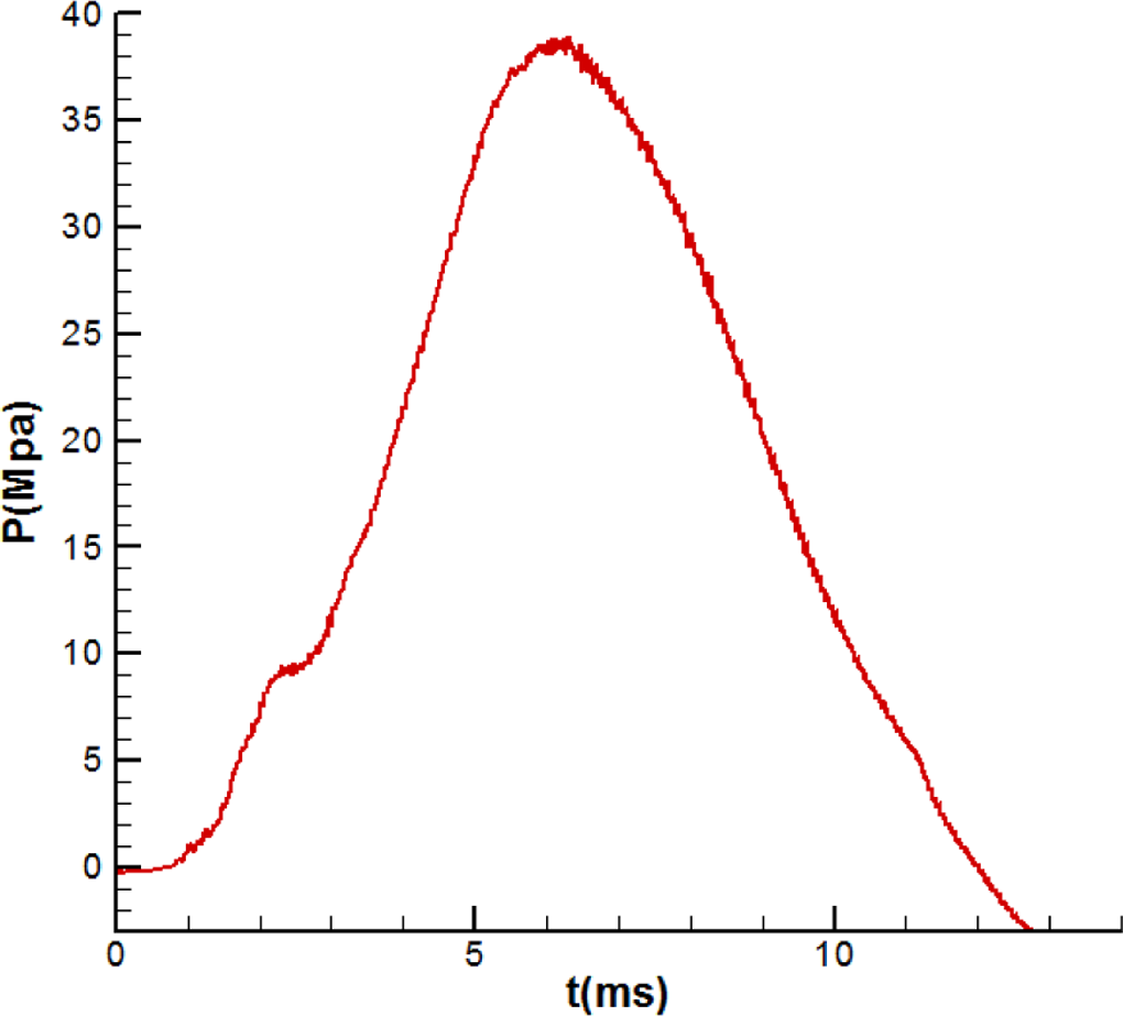
Pressure–time diagram obtained from experimental test.
Vessel inside temperature is calculated from internal ballistic analysis of double-base propellant combustion that is shown in Figure 9 and vessel outside temperature is ambient temperature. Figure 10 shows a schematic of two-dimensional from the vessel. For calculation of free heat convection coefficient, value 10
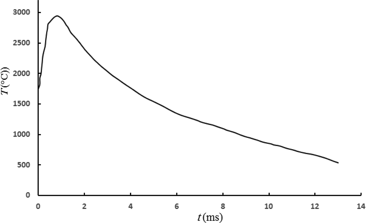
Change of vessel inside temperature versus time.
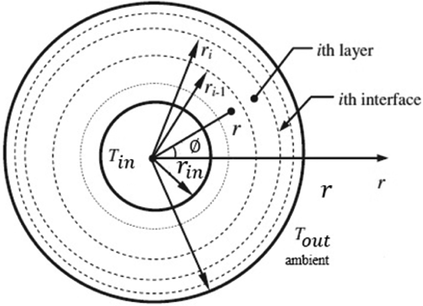
Schematic of two-dimensional from the cylindrical vessel and arrangement of layers.
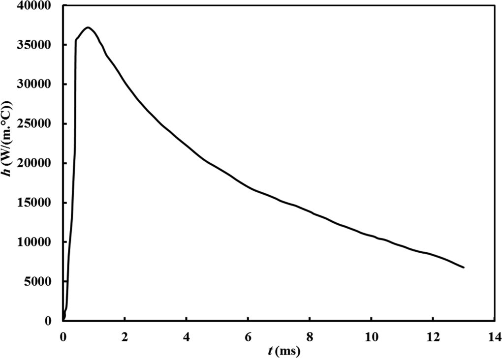
Change of convective heat transfer coefficient in heat gases versus time.
Boundary conditions are expressed as follows:
Boundary conditions for heat transfer analysis with layerwise theory: this type of boundary condition is as follows:
The continuity conditions at the interfaces (
where hout and hin are the heat convection coefficient for ambient air and heat gases (vessel outside and vessel inside), respectively; KNe and K1 are the heat conduction coefficient for up and down layers in cylindrical vessel; and
Boundary conditions for thrmoelastic analysis:
Clamped boundary condition: this type of boundary condition is as follows:

Simply supported boundary condition: this type of boundary condition is as follows:

By substituting the boundary conditions (equations (50) to (51)) into the thermoelastic governing equations (equations (47)), a system of algebraic equations with
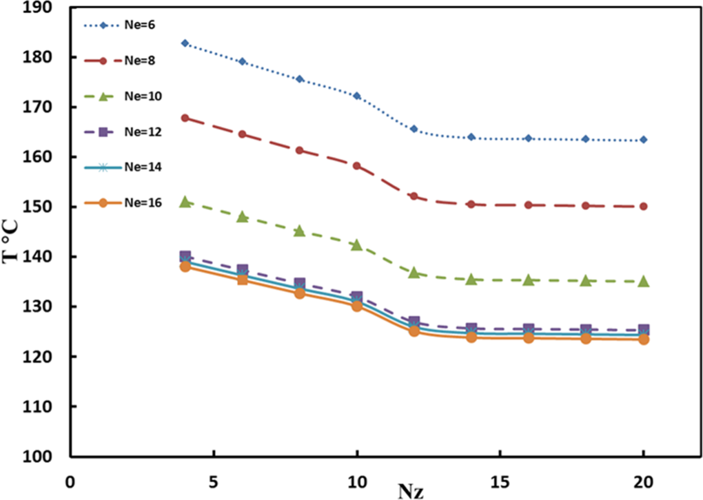
The convergence behavior of temperature field for DQM code at t=13 ms.
Figure 13 shows time histories of the radial displacement at the mid-surface of the cylinder with l = 300 mm for the two described boundary conditions. The results achieved by the DQM method are compared with those obtained by the ABAQUS software. It is observed that the distribution of the radial displacement near the ends exhibits a very low dependency on the type of boundary condition. As shown in figure, the comparison shows good agreement between the DQM algorithm and ABAQUS software. It is also seen that the radial displacement in the simply supported is about 20% more than from the clamped boundary condition in the maximum value.
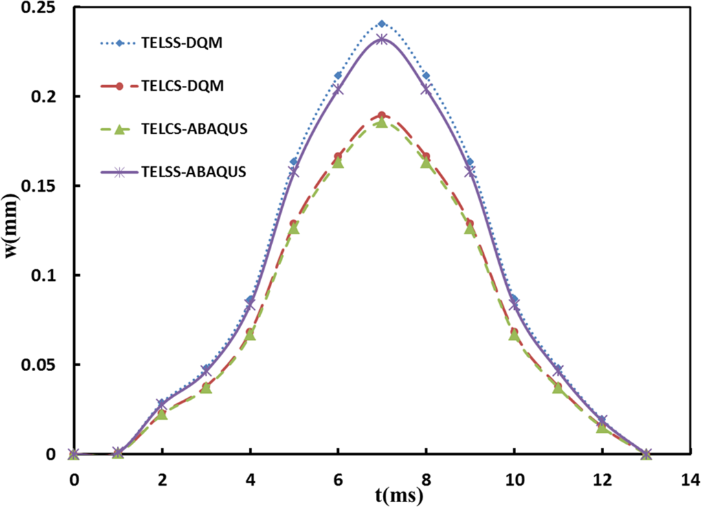
Time histories of the radial displacement at the mid-surface of the cylinder with l = 300 mm obtained by TELSS-DQM, TELCS-DQM, TELCS-ABAQUS, and TELSS-ABAQUS.
Figure 14 illustrates time histories of the von Mises stress at the liner with l = 300 mm for the simply supported boundary conditions and two types of loading. The results achieved by the DQM method are compared with those obtained by the ABAQUS software. The current solutions show a very good agreement with the ABAQUS results. It is also observed that the stress in the TELSS loading is between 0% and 50% more than from the ELSS loading.
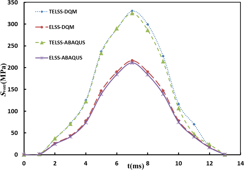
Time histories of the Von Mises stress at the liner with l = 300 mm obtained by TELSS-DQM, ELCS-DQM, TELSS-ABAQUS, and ELSS-ABAQUS.
Figure 15 demonstrates time histories of the fiber stress in the circumferential direction with l = 300 mm for the simply supported boundary conditions and two types of loading. It can be seen that the normal stress in the TELSS loading is between 0% and 34% more than from the ELSS loading. It is also observed that maximum stress for both types of loading appears at θ = 90°.
Time histories of the fiber stress in the circumferential direction with l = 300 mm obtained by TELSS-DQM and ELSS-DQM.
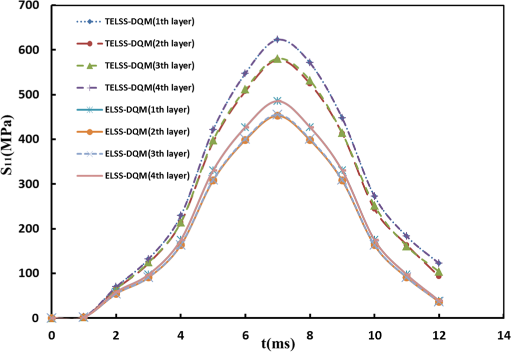
Figure 16 depicts time histories of the longitudinal stress at the liner with l = 0, 300, and 1200 mm for the simply supported boundary conditions and two types of loading. It can be seen that the stress in the TELSS loading is between 0% and 85% more than from the ELSS loading. It is also seen that the longitudinal stress is about half the amount of von Mises stress in the maximum value.
Time histories of the longitudinal stress at the liner with l = 0, 300, and 1200 mm obtained by TELSS-DQM and ELSS-DQM.
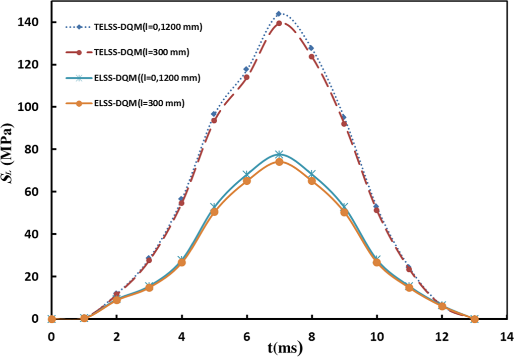
Time histories of the tangential stresses at the liner for the two described boundary conditions with = 0, 300, and 1200 mm are shown in Figure 17. The results predicted by the DQM algorithm are compared with those obtained by the ABAQUS software. It is observed that the distribution of the tangential stress near the ends exhibits a very low dependency on the type of boundary condition. As shown in Figure 17, the comparison shows good agreement between the DQM algorithm and ABAQUS software. It is also seen that the tangential stress in the clamped boundary conditions is nearly twice more than from the simply supported boundary conditions in the maximum value.
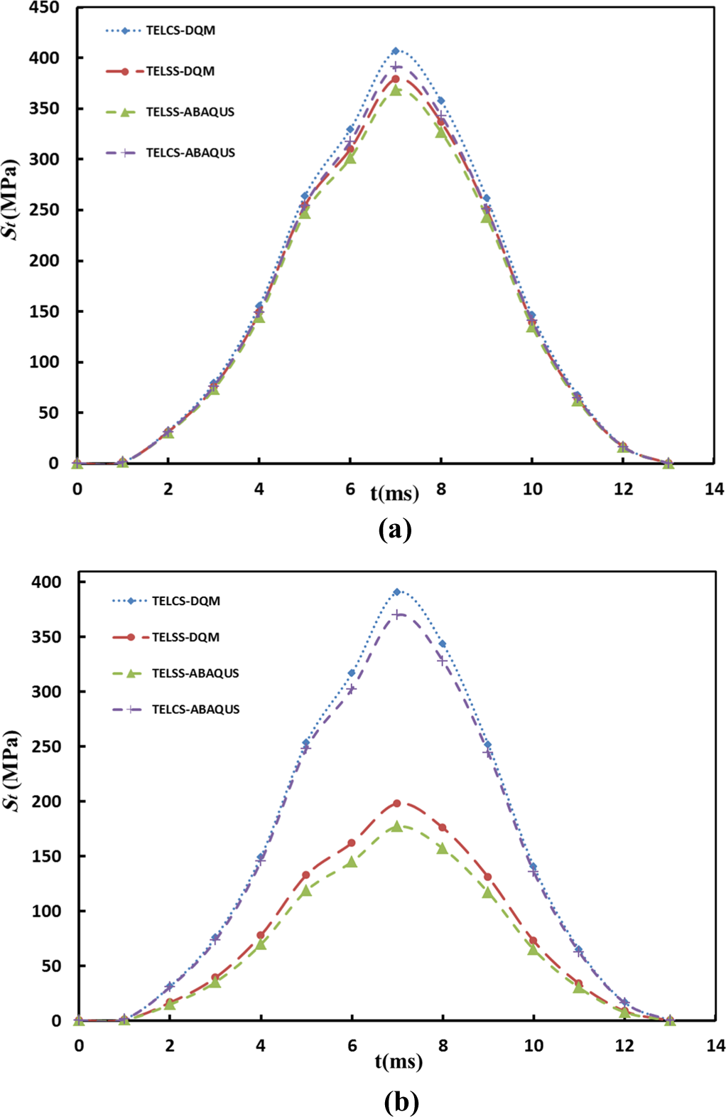
Time histories of the tangential stress in liner with (a) l = 300 mm and (b) l = 0 and 1200 mm obtained by TELCS-DQM, TELSS-DQM, TELSS-ABAQUS, and TELCS-ABAQUS.
The tangential and shear stresses with l = 300 mm in the thickness direction are shown in Figure 18 by TELSS and ELSS. The results predicted by the DQM algorithm are compared with those obtained by the ABAQUS software. It is observed that the distribution of the circumferential stress in 90° layers is ascending but in 75° layers is descending to mid-plane (the reference plane). Amount of shear stresses at the top and bottom of the laminate equal to zero. Note that interlaminar stresses exhibit apparent singular behavior near the intersection of the layers interfaces. The stress distributions in Figure 18 show good qualitative agreement between the DQM algorithm with results ABAQUS software.
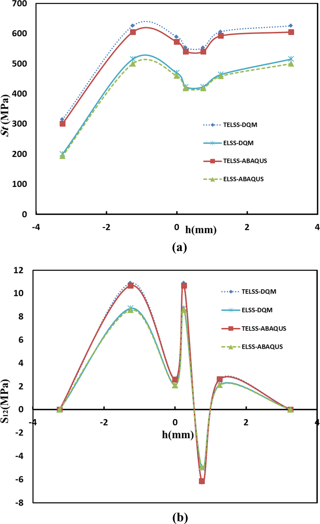
The stress with l = 300 mm in the thickness direction (a) tangential stress and (b) shear stress obtained by TELSS-DQM, ELSS-DQM, TELSS-ABAQUS, and ELSS-ABAQUS.
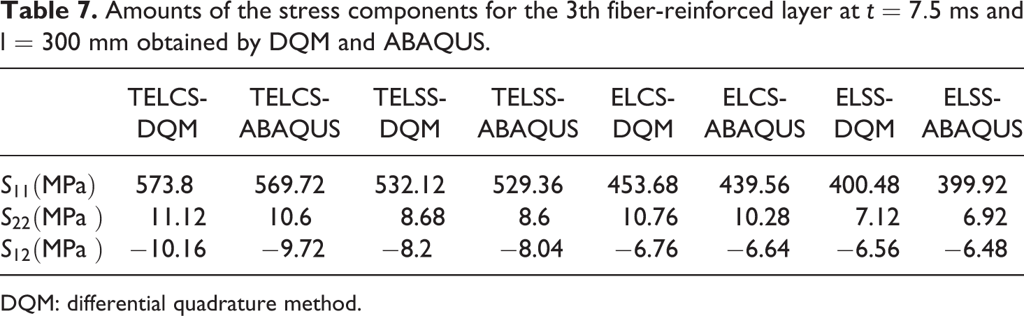
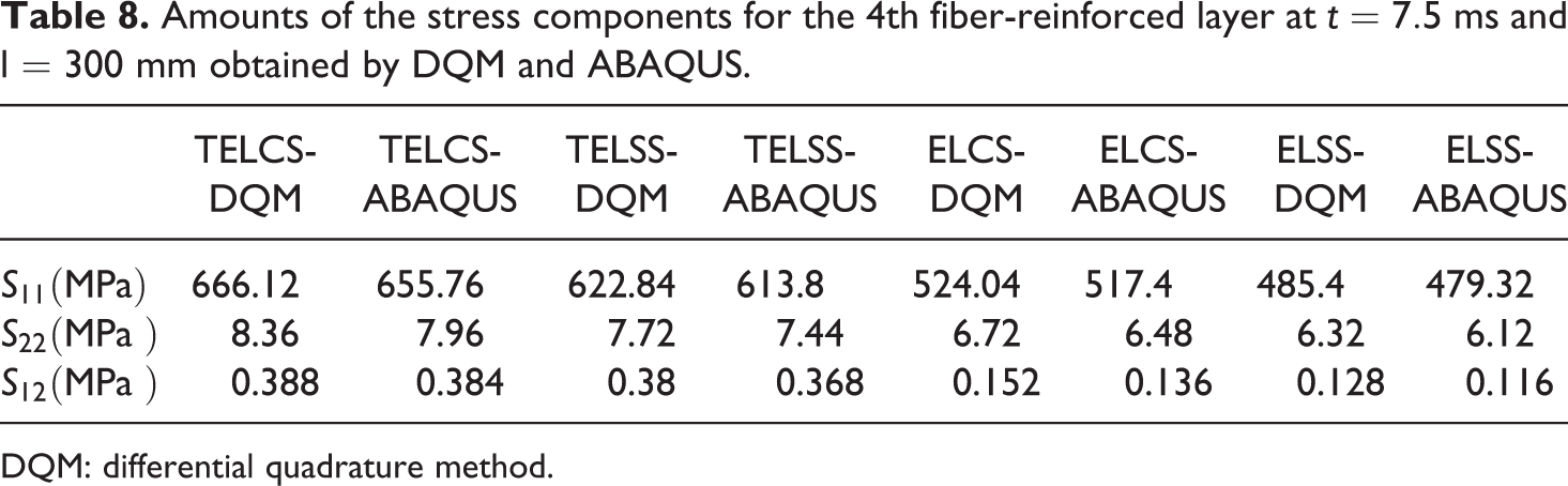
In Table 4, the stress components as well as the radial displacement for liner at t = 7.5 ms are obtained and compared with ABAQUS results for various types of boundary conditions and loading. The solutions presented show a good agreement between the DQM method and ABAQUS results. In Tables 5 to 8, the stress components for the 1th to 4th fiber-reinforced layer at t = 7.5 ms and l = 300 mm are presented for various types of boundary conditions and loading. The results of the DQM code are compared with those obtained by ABAQUS.
Amounts of the stress components as well as the radial displacement for liner at t = 7.5 ms and l = 300 mm obtained by DQM and ABAQUS.
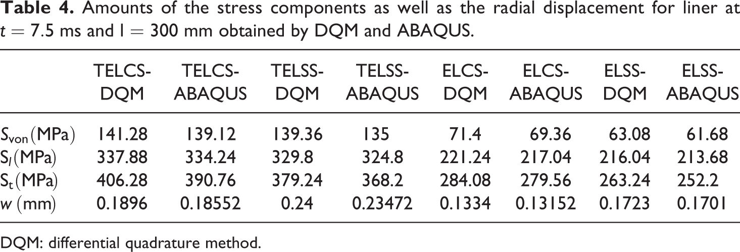
DQM: differential quadrature method.
Amounts of the stress components for the 1th fiber-reinforced layer at t = 7.5 ms and l = 300 mm obtained by DQM and ABAQUS.
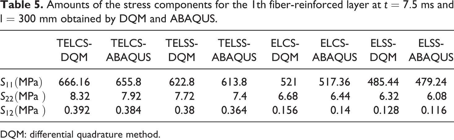
DQM: differential quadrature method.
Amounts of the stress components for the 2th fiber-reinforced layer at t = 7.5 ms and l = 300 mm obtained by DQM and ABAQUS.
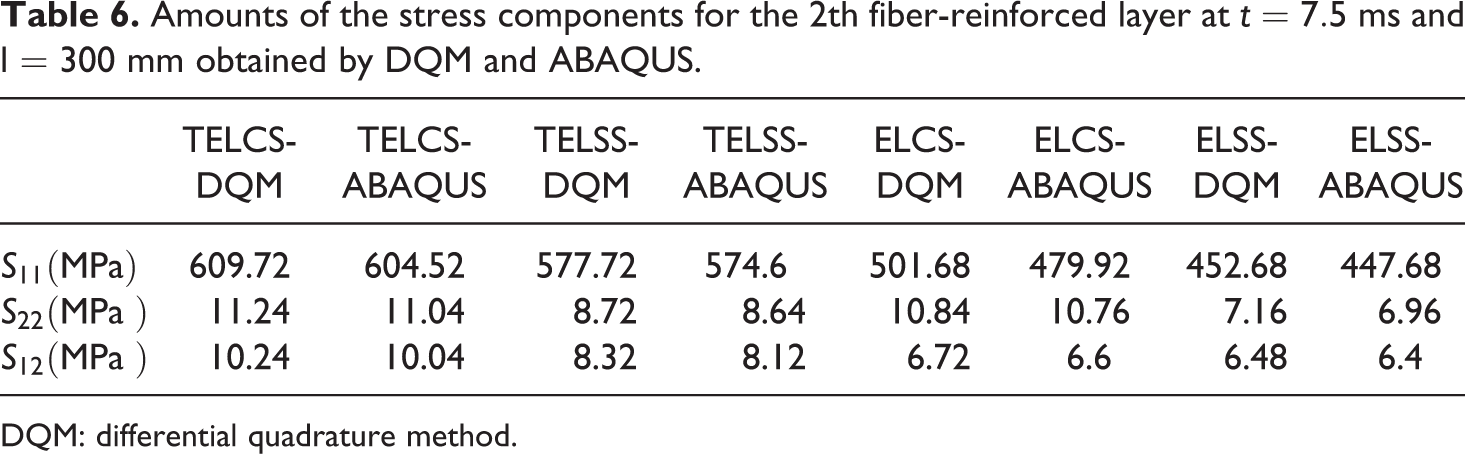
DQM: differential quadrature method.
Amounts of the stress components for the 3th fiber-reinforced layer at t = 7.5 ms and l = 300 mm obtained by DQM and ABAQUS.
DQM: differential quadrature method.
Amounts of the stress components for the 4th fiber-reinforced layer at t = 7.5 ms and l = 300 mm obtained by DQM and ABAQUS.
DQM: differential quadrature method.
All solutions show close agreements. The total CPU time to thermoelastic analysis of considered laminated shell with metallic liner is about 80 s using the DQM method. On the other hand, the results of the finite element solutions using the ABAQUS software use 36 times more CPU time than the DQM code for the same problem. Therefore, in comparison with the simulation of finite element method that require very fine meshes, the DQM method is an efficient way for numerical analysis due to less computational cost.
Conclusion
Comparison of thermoelastic stress with elastic stress in metal composite vessel is investigated under experimental dynamic load. Elastic analysis of laminated cylindrical shells is done by using FSDT. Thermoelastic analysis of laminated cylindrical shells is done by using the mixed layerwise and FSDTs with DQM. DQM is used to discretize the resulted governing equations while Newmark’s method is implemented to solve the problem in the time domain. The MATLAB programming code has been used to solve differential quadrature equations. It was observed that the fast convergence rate of the DQM method and its accuracy is confirmed by comparing the results with those obtained using ABAQUS software and also with the exact solutions. It was achieved significantly less computational efforts of the proposed approaches with respect to the finite element method. Also, calculation of temperature field with layerwise theory provides the ability to model accurately of laminated composite shells. Furthermore, comparative studies are done between two methods of elastic and thermoelastic stress, it is found that about 48% in the maximum amount higher stress in the thermoelastic state for the metal liner and 32% for the composite layers. Since the results of this research are derived from the experimental load can be used as criterion solutions for future studies.
Footnotes
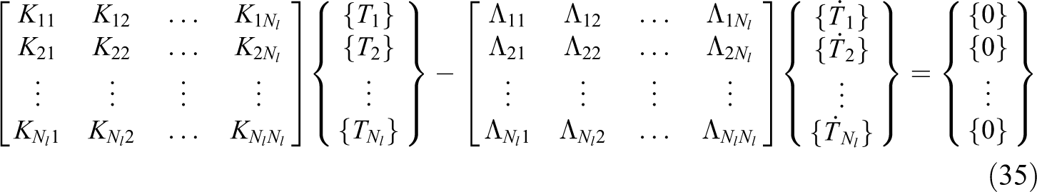
Appendix 1
The element stiffness matrices and thermal resultants:
Declaration of Conflicting Interests
The author(s) declared no potential conflicts of interest with respect to the research, authorship, and/or publication of this article.
Funding
The author(s) received no financial support for the research, authorship, and/or publication of this article.