
Abstract
In recent years, the application of polymer nanocomposites has been enormously increased, particularly in aerospace and automotive sector due to its lightweight and high specific strength. In this study, nanocomposite materials with polypropylene (PP) matrix and Cloisite 30B (C30B) as reinforcing nanofiller with Elvaloy AC 3427 (EA) as compatibilizer were manufactured by melt intercalation technique with the aid of twin-screw extruder (TSE). The C30B with EA was reinforced in the PP matrix at 1, 2, 3 and 5 wt%. The PP/C30B/EA nanocomposites were processed in TSE with different barrel zones such as conveying zone, melting zone, mixing zone and plasticizing zone which helps in achieving homogenous dispersion of C30B in PP matrix. The processing parameters of TSE are twin-screw speed (65 r/min), volumetric feeder’s screw speed (7 r/min), degassing zone pressure (40 mmHg), cooling length (50 cm) and humped temperature profile (170–220°C). The processed PP/C30B/EA was characterized using X-ray diffraction (XRD) for studying intercalation/exfoliation structure formation and transmission electron microscope (TEM) for studying the dispersion of C30B in PP matrix. The thermal characterization of PP/C30B/EA nanocomposites was investigated by differential scanning calorimetry (DSC), thermogravimetric analysis (TGA) and dynamic mechanical analysis (DMA). The addition of C30B at 5 wt% to PP/C30B/EA nanocomposites increased the DSC, TGA and DMA properties.
Keywords
Introduction
Polymer reinforced with fillers has received particular attention among researchers and industrial sectors in the last decade due to their improvement in thermal properties, mechanical properties, increased stiffness, greater stability and improvement in coefficient of thermal expansion. 1,2 In most of the scenario, the reinforcement is in the form of nanocomposite and they are termed as polymer nanocomposites. 2 Several researchers focused their work on modified nanoclays reinforced with several polymers. These modified nanoclays are made up of organic modified laminar silicate structures which form a hybrid organic–inorganic structure. These modified nanoclays are based on montmorillonite which is used in the small amount which improves the overall performance of polymer matrix at a low cost. 3,4 The improvement in properties of polymer nanocomposites relates to the factors like the dispersion of nanoclays in the polymer matrix and the structure formed during the manufacturing of polymer nanocomposites. The effective dispersion of nanoclays in the polymer matrix mainly depends on the presence of the polar group in the polymer and structural characteristics of the nanoclays. 2,5 The interaction between the nanoclays and the polymer matrix is essential for obtaining a high specific surface that nanoclays offer. For achieving these interactions, mixing process is used for breaking up of large clay particulate to small clay particulate matter and also for achieving homogenous dispersion of clay in the polymer matrix. 6,7
Several methods like solgel technology, 8 in situ polymerization 9 and melt intercalation method 1 are used for mixing of polymers with nanoclays to produce polymer nanocomposites. Among the above-said methods, melt intercalation method by twin-screw extruder (TSE) offer better mixing since the polymer is subjected to high shear stress and it provides a homogeneous dispersion of nanoclays in the polymer matrix. 10
Though there are many advantages of melt intercalation process, there is a chance of degradation problems during the melt intercalation process since it involves high temperature for manufacturing. During the melt intercalation process, a certain temperature is set for the manufacturing. Apart from the polymer matrix degradation, the degradation temperature of the filler must be considered for effective dispersion. The onset decomposition temperature of the filler is also vital because the polymer is processed in a TSE normally above 100–150°C.
Several researchers have discussed the degradation process encountered during the manufacturing of the polymer nanocomposites. Finnigan et al. 11 prepared thermoplastic polyurethane (TPU) nanocomposites by twin-screw extrusion and solvent casting to compare these methods. Two types of TPU, a soft elastomer and hard elastomer, consist of same soft and hard segments in different relative amounts. The wide-angle X-ray diffraction (XRD) studies revealed intercalated structure on both the manufacturing methods which was mainly during to better driving force between the polymer and the fillers.
Davis et al. 12 processed MMT/PA6 nanocomposites by TSE at 240°C and noticed that the nanoclays degraded to an extent which was related to the residence time of the polymers inside the extruder. They also concluded that preheating of polymers was vital before the manufacturing of polymer nanocomposites by TSE. A strong odour may also indicate degradation which decreases the physical and mechanical properties of the processed polymers. The presence of discolouration or the presence of dark streak is formed due to the excess heat applied or excess TSE screw revolution per minute during the manufacturing. Many researchers have developed nanoclays with some chemical modification methods to eliminate degradation of fillers while processing it in TSE. Chang et al. 13 and Gilman et al. 14 developed clays which are modified by certain methods which increase the thermal stability of the nanoclays which were used for manufacturing of polymer nanocomposites at elevated temperatures.
The formation of polymer nanocomposite by TSE depends on (i) temperature profile selected, (ii) TSE’s screw speed, (iii) the residence of polymers inside the TSE barrel, (iv) processed MMT/PA6 nanocomposites’ volumetric feeder’s revolution per minute, (v) selection of cooling medium and (vi) selection of cooling length. The selection of process parameters for the twin-screw extrusion must be selected properly for attaining bettermixing characteristics. 15
Dynamic mechanical analysis (DMA) is the test which is carried out over a wide range of temperatures, which provides the details about the viscoelastic behaviour of polymer materials. Yin et al. 16 carried out DMA tests for materials like polycarbonate and acrylonitrile–butadiene–styrene and reported that the storage modulus of the materials decreases with increase in temperature with a trend exhibiting different for each material. The different trend may be due to the various states of material like glassy, viscoelastic and rubber states. Storage modulus may be defined as the elastic response of the materials and loss modulus is defined as strain energy lost due to the friction and internal motions.
Polypropylene (PP) is one of the commonly used thermoplastic materials due to their characteristics like low density, low melting point and the ease of manufacturing. The PP does not have any polar group in their structure which hinders the formation of polymer nanocomposites when nanoclays are added. 17,18 To increase the affinity and dispersion of nanoclays in PP matrix, a third material called compatibilizer is added. The compatibilizer must be bifunctional with one end of the groups reacting with the nanoclay and the other end of group reacting with the PP polymer chains. Kawasumi et al. 19 found that the addition of functional polyolefin oligomer to PP can increase the interaction between the PP and the nanoclays. Numerous researches have been carried out with different compatibilizers, and they have reported the improvement in end properties. 20 –23 Compatibilizer must be selected based on the polymer matrix selected. 24
Several researchers have reinforced polymers with fillers with the aid of TSE, but the process parameter selection for manufacturing of PP/C30B/EA nanocomposites by twin-screw extrusion process has not been discussed elsewhere. Based on the past literature survey, it was found that there was no study related to processing and characterization of PP/C30B/EA nanocomposites. In this study, PP was selected as a thermoplastic matrix, Cloisite 30B (C30B) as a reinforcing filler and Elvaloy AC 3427 (EA) as compatibilizer. In this work, the process parameter selection for the manufacturing of PP/C30B/EA nanocomposites by twin-screw extrusion was selected, and the same was applied during the processing. The morphology characterization (XRD) and thermal characterization (differential scanning calorimetry – DSC, thermogravimetric analysis – TGA and DMA) were carried out for the processed PP/C30B/EA nanocomposites.
Experimental
Materials
The PP was used as a thermoplastic matrix with a grade name Repol H110MA which was obtained from Reliance Industries, India, which has a melt flow index of 11 g/10 min and a density of 890 kg/cm3. The C30B was used as a reinforcing nanofiller which was procured from Southern Clays (Dunedin, New Zealand). The EA was used as a compatibilizer which was procured from DuPont (Mumbai, India). The EA is the copolymer of ethylene (73 wt%) and butyl acrylate (27 wt%). In this work, the weight percent of C30B was kept at 1, 2, 3 and 5 wt% in the PP matrix.
The PP/C30B/EA nanocomposite manufacturing by melt intercalation method
Initially, PP and EA were preheated in a hot air oven to remove absorbed moisture. The manufacturing of PP/C30B/EA nanocomposites was carried out using a TSE with a length/diameter (L/D) ratio of 40 which was supplied by Flytech Engineering, Chennai, TN. The parameters like volumetric feeder’s screw revolution per minute, twin-screw speed revolution per minute, temperature profiles and temperature of barrel zones, degassing zone pressure and cooling length of polymers must be selected before processing of PP/C30B/EA nanocomposites. The PP/C30B/EA nanocomposite strands from the 3 mm die were water- and air-cooled. It was cut into required shape by a pelletizer.
Characterization of C30B dispersion and intercalation/exfoliation formation
The XRD was carried out to find out the d-spacing and the formation of intercalation/exfoliation structure formed in PP/C30B/EA nanocomposites during the twin-screw extrusion process. The scanning angle was selected from 5° to 20°. 25 The d-spacing was calculated using the Bragg’s equation (nλ = 2dsinΘ). Transmission electron microscope (TEM [Model - Jeol/JEM 2100]) (JEOL) was used for studying the dispersion characteristics of C30B in PP matrix in the presence of EA as a compatibilizer. The TEM analysis was carried out using JEOL model JEM 2100. The ultramicrotome cutter was used to cut samples under cryogenic conditions.
Thermal characterization of manufactured PP/C30B/EA nanocomposites
Thermal characterization of PP/C30B/EA nanocomposites was carried out using DSC, TGA and DMA. The samples for DSC and TGA were in the form of pellets, and the mass weight of pellets was approximately 3–5 mg. The DSC was carried out using Mettler Toledo DSC 822e, and the scan temperature range was maintained from 30°C to 220°C in the nitrogen atmosphere at a heating rate of 10°C/min. The PP/C30B/EA nanocomposite samples were cooled at a rate of 10°C/min. The DSC test was carried out for finding the melting temperature (T m), crystalline temperature (T c), specific melting enthalpy (ΔH f) and degree of crystallinity (X c).
The thermal stability of PP/C30B/EA nanocomposites was studied using TGA. It is used to determine the selected characteristics of materials that exhibit either mass loss due to decomposition and oxidation or loss of volatiles. The TGA was carried out using TGA (Model - TGA 4000) 4000 Perkin Elmer (Perkin Elmer). The samples were heated from 30°C to 600°C at a rate of 10°C/min in a nitrogen environment. The change in weight of PP/C30B/EA nanocomposite samples concerning temperature was noted. The parameters like onset temperature (°C), decomposition temperature (°C) and char residue (wt%) values at 600°C was observed.
The DMA is used to study the viscoelastic behaviour of the polymers and polymer composites. In this work, the DMA characterization of the manufactured PP/C30B/EA nanocomposites was carried out with a specimen size of 50 × 10 × 4 mm. The PP/C30B/EA nanocomposite samples were heated from 30°C to 190°C at the rate of 10°C/min under the load of 1000 mN at a frequency of 5 Hz. 26 During the DMA characterization, the parameters like storage modulus and loss modulus of PP/C30B/EA nanocomposites were investigated.
Manufacturing of polymer nanocomposites in different screw zones in a TSE
The manufacturing of polymer nanocomposites was carried out using TSE. The specification of TSE used in the study has a screw diameter of 28 mm, high-density cartridge heater, cooling using air, the barrel length of 1120 mm and volumetric feeder capacity of 10 kg/h.
Different screw zones inside a TSE
The part of TSE is depicted in Figure 1 with a varying pitch of screw in various zones. It consists of different zones such as inlet feed zone, plasticizing zone, melting zone, mixing zone, degassing zone and pumping zone which are discussed in the following sections. The pitch element of the screw in each zone varies according to the function of the screw zones. Lertwimolnun and Vergnes 27 concluded that screw profiles are one of the influencing factors in the manufacturing of polymer nanocomposites using a TSE.
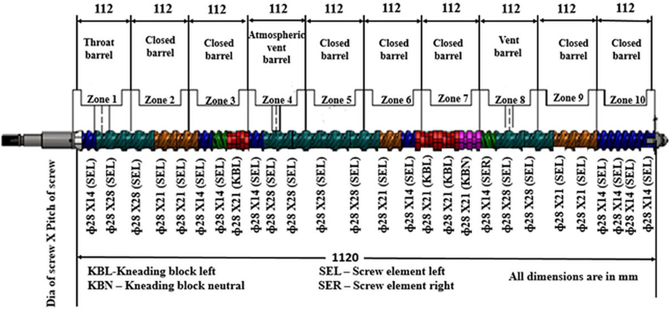
Screw profile inside a twin-screw extruder (Figure reproduced with permission of Flytech Engineering, Chennai).
Inlet feed zone of TSE (Zone 1)
The screw element at the inlet feed zone has a pitch of 14 mm. This screw element stops the material flowing back towards the screw seal. Immediately after 14-mm pitch, the screw element pitch is increased to 21 mm with an undercut which provides space for the materials to enter into the extruder which moves the material to the next zone.
Plasticizing and melting zone of TSE (Zone 2–Zone 3)
The extruder motor supplies 80–90% of heat to plasticize the polymers. As the polymers are conveyed to the next zone, there is a conductive heat transfer to polymers from the barrel walls. The value of pitch of each screw inside TSE changes at each zone. These changes in pitch values vary the free volume, and the mixing takes place inside the TSE. The materials are usually preheated and compressed from barrel Zone 1 to barrel Zone 3. Heat is not applied at barrel Zone 1, and it is water-cooled to avoid the premature heating of the polymers in the inlet zone itself during the manufacturing. 28 The polymer nanocomposites materials are preheated at barrel Zone 2, and it is compressed at barrel Zone 3.
Melt conveying zone of TSE (Zone 4–Zone 5)
Once the material melts, it moves to the melt conveying zone (i.e. barrel Zone 4 and barrel Zone 5). The melt conveying section used a high screw pitch of 28 mm when compared to the 14 mm at barrel Zone 3 which reduces the work, and it also minimizes the pressure on the melt surface.
Mixing zone of TSE (Zone 6–Zone 7)
The mixing of the polymers inside the extruder barrel can be either distributive and or dispersive mixing. Distributive mixing is done by a low shearing process, which distributes the particles uniformly in the entire polymer melt surface. It is applied to fibrous materials, high aspect ratio filler materials and sensitive polymers. Dispersive mixing is used when there is a need for breaking of large particles to small particles and dispersing the smaller particles in the entire polymer melt stream. 15,29
The kneading block is an element which is used for mixing purposes. Kneading block is defined by the characteristics like (i) length of kneading block, (ii) number of lobes present in kneading block, (iii) distance between each lobe, (iv) angle between each lobe and (v) conveying direction of each lobe. 28 The mixing process is typically carried out in barrel Zone 7 and barrel Zone 8. It has two screw elements at left orientation, two kneading block at left orientation (KBL) and one at neutral kneading block (NKB). The polymer flow through the gap between the KBL lobes and the mixing takes place between the lobes. The two KBL is present in the mixing zone ensures proper mixing of polymers and nanoclays inside a TSE. The NKB is present after KBL in the mixing zone. There are five lobes, which are at 90° to each lobe. The polymer enters in the gap between the NKB when it is rotating, and it moves the polymers forward consistently to the next zone.
Degassing pressure of TSE (Zone 8)
In the TSE, there is an opening in the barrel Zone 8 where the moisture or any other form of impurities present in polymer melt stream is removed. 30 The pitch of the screw element in barrel Zone 8 is increased to 28 mm from 14 mm which creates a low pressure at that barrel Zone 8 which in turn moves the polymers very slowly. During the manufacturing of polymers, a vacuum is applied to the vented barrel to remove the moisture and other impurities present. The vacuum pressure applied depends on the melting point of the selected material. The temperature in Zone 8 must be set at a lower value than Zone 7 for avoiding polymer expulsion through vent barrel. Due to a decrease in temperature values, the polymers get solidified at that barrel Zone 8, and it avoids the expulsion of material through vent barrel.
Pumping zone of TSE (Zone 9–Zone 10)
The last area in the TSE is pumping zone, and it moves the material forward to the die zone from the previous zones. The pitch of the barrel Zone 9 is reduced from 28 mm to 21 mm, and it is still further reduced to 14 mm in barrel Zone 10. These smaller pitch elements ensure that they provide better pumping capacity of polymers to the die zone. 31
Selection of process parameters for twin-screw extrusion of PP/C30B/EA nanocomposites
The parameters selected before the manufacturing of various wt% PP/C30B/EA nanocomposites using a TSE are
28
as follows: ► Volumetric feeder’s screw speed for manufacturing of PP/C30B/EA nanocomposite material ► Selection of the temperature profile and temperature of barrel zones for the TSE to manufacture of PP/C30B/EA nanocomposite material ► TSE’s screw speed for manufacturing of PP/C30B/EA nanocomposite material ► Degassing zone pressure for manufacturing of PP/C30B/EA nanocomposite ► Cooling length for the manufactured PP/C30B/EA nanocomposite strand.
The parameters must be selected properly before the twin-screw extrusion of PP/C30B/EA nanocomposites, which are discussed in the following sections.
Volumetric feeder’s screw speed for manufacturing of PP/C30B/EA nanocomposite material
Feeding of the polymers inside the TSE during the twin-screw extrusion process mainly depends on characteristics like extruder design and the material is fed inside the TSE. 15 The feeder is usually situated directly above the feed opening in TSE which directly feeds the materials inside the TSE. The feeding of the polymer is done either by a volumetric feeder or gravimetric feeder. The volumetric feeder is used in most of the cases as the inlet flow of materials will be uniform during the entire extrusion process. The volumetric feeder has a deep and narrow screw channel which helps the material in flowing correctly inside the TSE. 15,28
The feeding of PP polymers was done by volumetric feeder, and it was set at various speeds like 25, 20 and 15 and the twin-screw rotation inside the extruder got jammed due to more amount of materials gets stuck between the two rotating screws leading to stoppage of screw rotation during the twin-screw extrusion process. Finally, after many trial-and-error experiments, the inlet revolution per minute was set to 7 r/min. Altomare et al. 32 also concluded that the volumetric feeder’s screw revolution per minute selection depends on the processing conditions.
Selection of the temperature profile and temperature of barrel zones for the TSE to manufacture of PP/C30B/EA nanocomposite material
The temperature profiles during the twin-screw extrusion process depend on the factors like (i) type of polymers selected, (ii) fillers selected and (iii) throughput rate. There are four types of temperature profiles commonly used in a TSE for manufacturing shown in Figure 2.
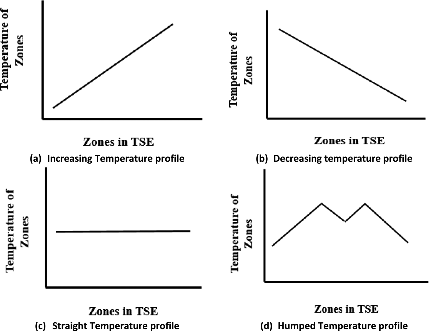
Typical temperature profiles used in a twin-screw extruder.
The extrusion process is the transfer of energy from motors, sometimes acting as a heater and sometimes to cool the plastic, thus converting from solid to melt. It is essential that the input materials must be in sufficient viscous state to push it forward to the next zone of TSE. The heat is either provided by internally by friction and also by applying external heat, which is kept outside of the barrel using high-density cartridge heaters. The barrel zones are water-cooled or air-cooled. The temperature profile which is selected lower than the melting rate of the polymer may not melt the polymer fully which leads to the consolidation of the material between the screws which may also stop the movement of the polymers to the next zone. In case the selection of temperature is too high, it may also lead to the degradation of polymers which also leads to the reduction in the properties of the processed polymer. 15
The temperature during the extrusion process is set from the inlet area (i.e. feed area) to the die zone. The number of barrels varies from 4 to 12, and it depends on the design of the TSE. In most of the cases, the humped temperature profile was selected, and it was used in this study. In this work, the temperature of the zones of the extruder was set at 170–220°C as shown in Figure 3. The inlet zone (i.e. feed zone – barrel Zone 1 and barrel Zone 2) temperature is set at the temperature lower than the melting point of the PP matrix. It is usually done to avoid the premature melting of the polymers which might stick to the inlet zone and the materials may get choked at the inlet zone itself. The temperature of the barrels was consecutively increased from barrel Zone 3 to barrel Zone 7. As vent barrel is present in barrel Zone 8, the temperature was decreased at that particular zone as shown in Figure 5 for devolatilization purpose and it was again increased at barrel Zone 9. The temperature from barrel Zone 10 to the die area was decreased for achieving a good flow of PP/C30B/EA nanocomposite in the die area.
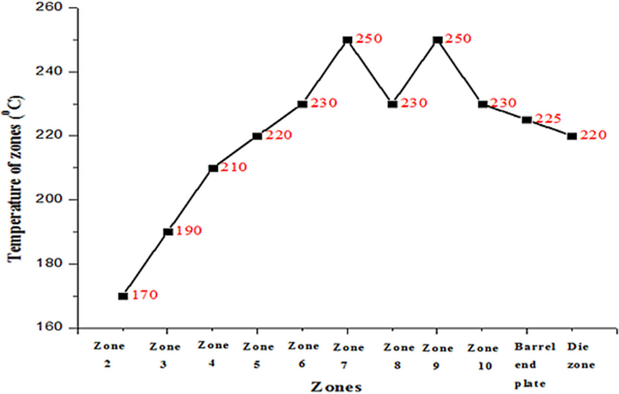
Temperature set at different zones of twin-screw extruder for manufacturing of PP/C30B/EA nanocomposites. PP: polypropylene; C30B: Cloisite 30B; EA: Elvaloy AC 3427.
The temperature of the die zone is the next critical parameter during the twin-screw extrusion process. The temperature of the die zone must be selected properly for ensuring the proper material flow at the exit of the extruder. The TSE has a die with a 3-mm hole in it, and the output of PP/C30B/EA nanocomposite was in the form of strands. Initially, the temperature of the die zone was set at 250°C, and the PP/C30B/EA nanocomposite materials from the extruder die were in liquid form, and it is hard to draw in the form of strands. The temperature of the die zone was reduced to 200°C, and the strands from the extruder are hard to draw as PP/C30B/EA nanocomposite materials were in a solidified state in die region itself. Finally, the temperature of the die zone was set at 220°C which was suitable for drawing the PP/C30B/EA nanocomposite strands.
The TSE’s screw speed for manufacturing of PP/C30B/EA nanocomposite material
The TSE’s screw speed must be optimized during the twin-screw extrusion process as it decides the residence time of the material inside the barrel. Residence time in a TSE is essential because it is one of the significant factors deciding the properties of processed nanocomposites. 32 If the screw speed is too low (i.e. 40 r/min), there is an increase in residence time, which resulted in degradation of PP/C30B/EA nanocomposites. When the residence time was more, there was a decrease in PP/C30B/EA nanocomposites’ melt viscosity inside the barrel. These reductions in viscosity hinder the cohesive force between the C30B and PP matrix, and it may facilitate the PP matrix to diffuse out of C30B clay galleries. When the screw speed was high (i.e. 100 r/min), there was an incomplete mixing of C30B with PP matrix was noted which was due to the short residence time. Finally, the TSE’s screw speed was selected at 65 r/min for the manufacturing of PP/C30B/EA nanocomposites.
Degassing zone pressure for manufacturing of PP/C30B/EA nanocomposite
The moisture or any other form of impurities present in PP/C30B/EA nanocomposites’ melt stream has to be removed for ensuring the better properties of the processed polymer. 33 During the manufacturing of PP/C30B/EA nanocomposites, vacuum is applied to the vented barrel to remove the moisture and other impurities from the PP/C30B/EA nanocomposites. The vacuum pressure applied depends on the melting point of the material. In this study, a vacuum pressure of 50 mmHg is selected. From Figure 3, it can be noted that the temperature at barrel zone 8 is reduced for partial solidification of the PP/C30B/EA nanocomposite material inside the extruder barrel. Alshahrani et al. 33 concluded that degassing zone pressure is one of the essential factors which determine the final properties of processed polymers.
Cooling length for the manufactured PP/C30B/EA nanocomposite strand
The cooling of processed nanocomposite strand material from the extruder die is either cooled using water, air or by any other cooling medium. 34 The PP is a semi-crystalline polymer which has a rapid solidification rate. The cooling rate plays a vital role in determining the product performance, and it depends on the issues like cooling medium, the thickness of the polymer strand and the amount of cooling. The cooling medium selected was water, and the amount of water-cooling of PP/C30B/EA nanocomposite strands must be optimized before manufacturing. 15
Initially, the water-cooling of PP/C30B/EA nanocomposite strand was cooled for entire 120 cm, and there was a shrinkage of PP/C30B/EA nanocomposite strands. The outer layer of the PP/C30B/EA nanocomposite strands cools very quickly as it is in contact with the cooling medium and forms a hard skin on the outer surface. The inner layer of the PP/C30B/EA nanocomposite strands cools at a different rate, and it leads to the shrinkage of the PP strand which results in a decreased cross section of the strand. The cooling length was still reduced to 90 and 60 mm, and still there was a shrinkage of PP/C30B/EA nanocomposite strands. When the cooling length was set at 40 mm, the cooling was sufficient, and there was no shrinkage of PP/C30B/EA nanocomposite strands.
Extrusion parameters for manufacturing of PP/C30B/EA nanocomposites
The extrusion parameters of PP/C30B/EA nanocomposites using a TSE were selected from trial-and-error experiments, and they are listed in Table 1.
Process parameters for manufacturing of PP/C30B/EA nanocomposites by TSE.
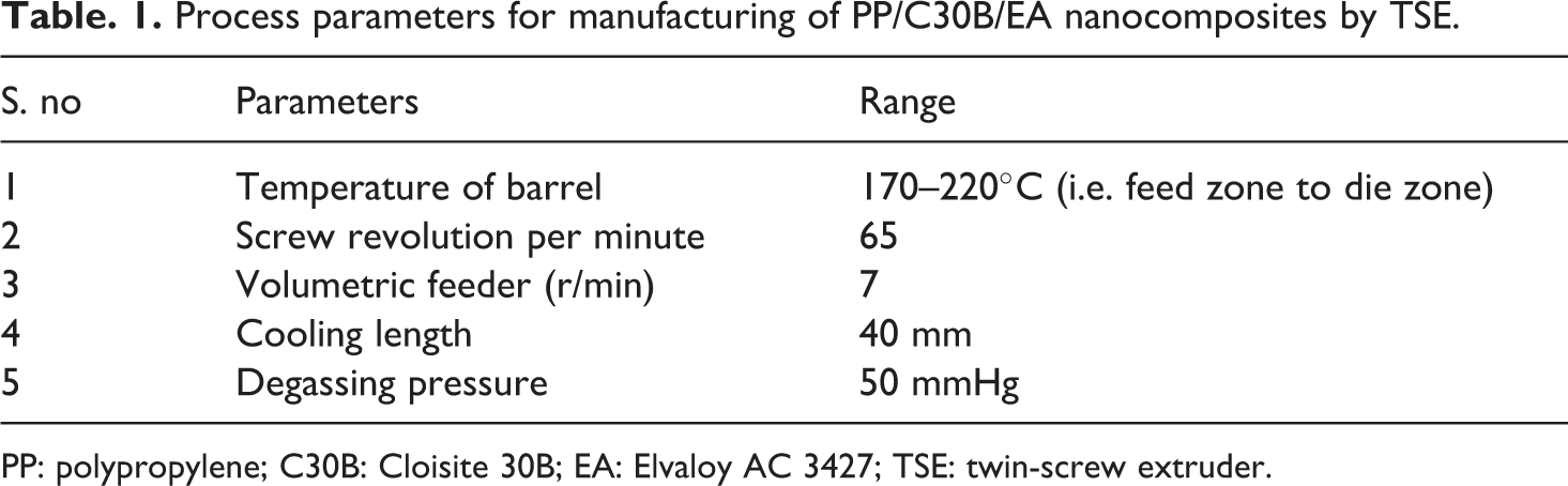
PP: polypropylene; C30B: Cloisite 30B; EA: Elvaloy AC 3427; TSE: twin-screw extruder.
Characterization of manufactured PP/C30B/EA nanocomposites
Intercalation/exfoliation formation of manufactured PP/C30B/EA nanocomposites
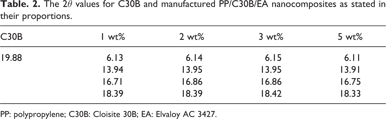
The twin-screw extrusion process must increase the d-spacing of nanoclays to intercalate the polymer chain (intercalation) or to break the crystal structure of nanoclays which ensures the maximum specific surface and contact (exfoliation) between the organic modifier present in nanoclays and polymer chains. The XRD spectra of C30B and processed PP/C30B/EA nanocomposites at different weight percentages are shown in Figure 4. The 2θ values of C30B and manufactured PP/C30B/EA nanocomposites are tabulated in Table 2.
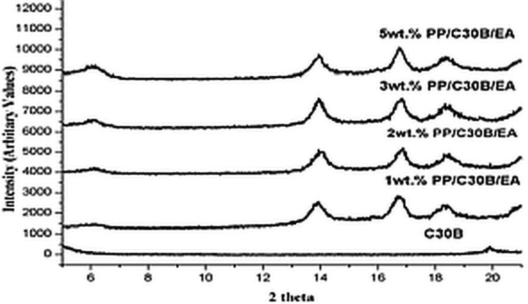
The XRD spectra of C30B and manufactured PP/C30B/EA nanocomposites in stated proportions. XRD: X-ray diffraction; PP: polypropylene; C30B: Cloisite 30B; EA: Elvaloy AC 3427.
The 2θ values for C30B and manufactured PP/C30B/EA nanocomposites as stated in their proportions.
PP: polypropylene; C30B: Cloisite 30B; EA: Elvaloy AC 3427.
The XRD spectra of C30B show a peak at a 2θ angle of 19.88° with the d-spacing of 4.46 Å. The C30B shows only one peak within the scan angle of 5–20°, and it will act as a reference peak for studying the manufactured PP/C30B/EA nanocomposite structure formation (intercalation/exfoliation). The addition of C30B to PP matrix increases the d-spacing, and there is a decrease in 2θ values. The peaks of PP/C30B/EA nanocomposites shifted to lower angles, and there was peak broadening which was due to the C30B lamellae separation during the twin-screw extrusion process which resulted in the formation of polymer nanocomposites. The initial 2θ value of the PP/C30B/EA nanocomposite is found at 6.13, 6.14, 6.15 and 6.11° as shown in Figure 4 with the d-spacing of 14.40, 14.45, 14.45 and 14.46 Å. The shift in 2θ values of PP/C30B/EA nanocomposite material to lower values as well as the increase in values of d-spacing when compared to C30B resulted in the formation of intercalated structure. The formation of the intercalated structure of manufactured PP/C30B/EA nanocomposites is due to the combined effect of shear forces produced during the twin-screw extrusion process and the diffusion of PP molecules inside C30B galleries which is due to the polar groups present in the EA compatibilizer.
C30B dispersion in PP matrix
The XRD provides information about the structure formed in manufactured PP/C30B/EA nanocomposite, but it does not give any information regarding the dispersion of C30B in PP matrix. The most direct measure of the dispersion of this C30B in PP matrix in nanometre scale is studied using TEM. 35 The cryo-thin specimen of PP/C30B/EA nanocomposites is used to examine the dispersive characteristics of C30B in PP matrix. The TEM images of 2 and 5 wt% PP/C30B/EA nanocomposites are shown in Figure 5(a) and (b). The dispersion of C30B was fine at 2 wt% PP/C30B/EA nanocomposites as shown in Figure 5(a). When the addition of C30B was at 2 wt%, little agglomeration was also formed because it was not always possible to disperse C30B in the individual forms. When the C30B was at 5 wt% in PP/C30B/EA nanocomposites, the force required to break down the C30B to finer particles was not enough as they had little tendency to be dispersed finely in the PP matrix which resulted in the formation of the agglomerated structure as shown in Figure 5(b). Similar kind of observations like fine dispersion and agglomerated structure formation was also done by Mirjalili et al. 36 in the case of PP/nano α-Al2O3 composites.
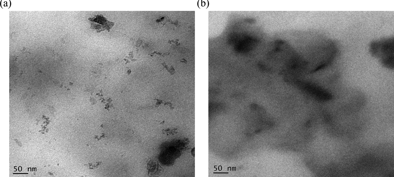
(a) TEM of 2 wt% PP/C30B/EA nanocomposites. (b) TEM of 5 wt% PP/C30B/EA nanocomposites. PP: polypropylene; C30B: Cloisite 30B; EA: Elvaloy AC 3427; TEM: transmission electron microscope.
Differential scanning calorimetry of manufactured PP/C30B/EA nanocomposites
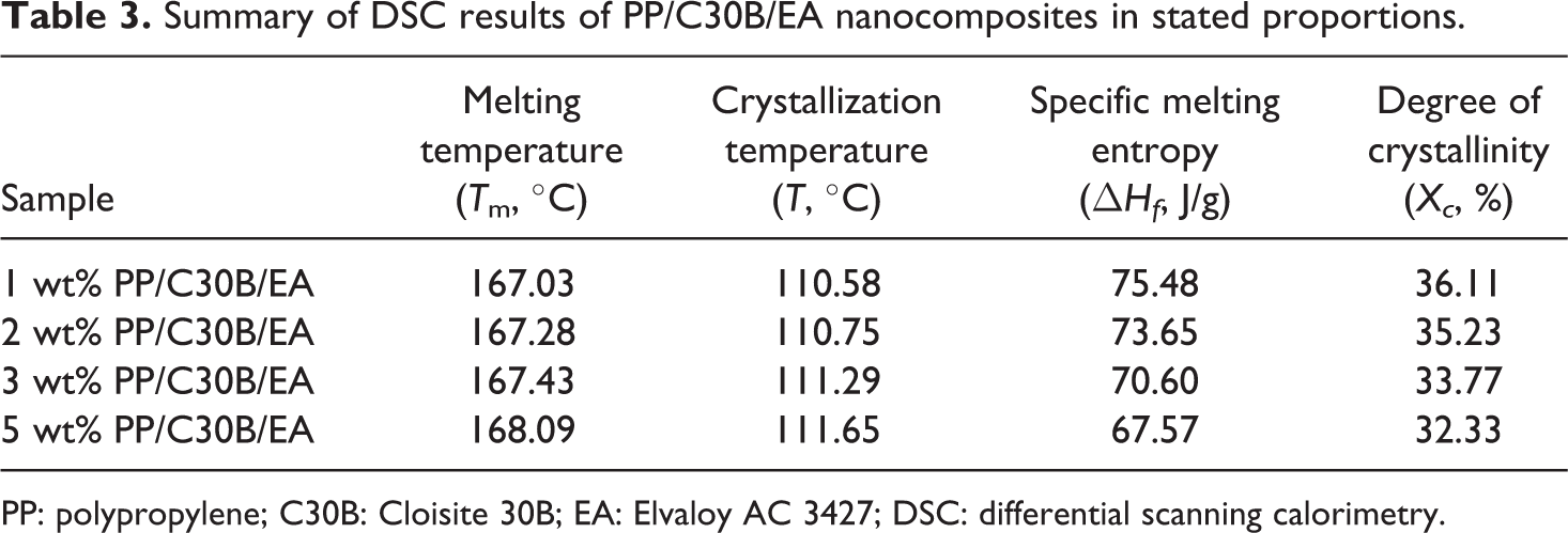
Figure 6(a) and (b) shows the heating and cooling thermograms of 1, 2, 3 and 5 wt% PP/C30B/EA nanocomposites. Table 3 shows the parameters like melting temperature (T m), crystallization temperature (T c), specific melting entropy (ΔH f) and degree of crystallinity (X c).
Summary of DSC results of PP/C30B/EA nanocomposites in stated proportions.
PP: polypropylene; C30B: Cloisite 30B; EA: Elvaloy AC 3427; DSC: differential scanning calorimetry.
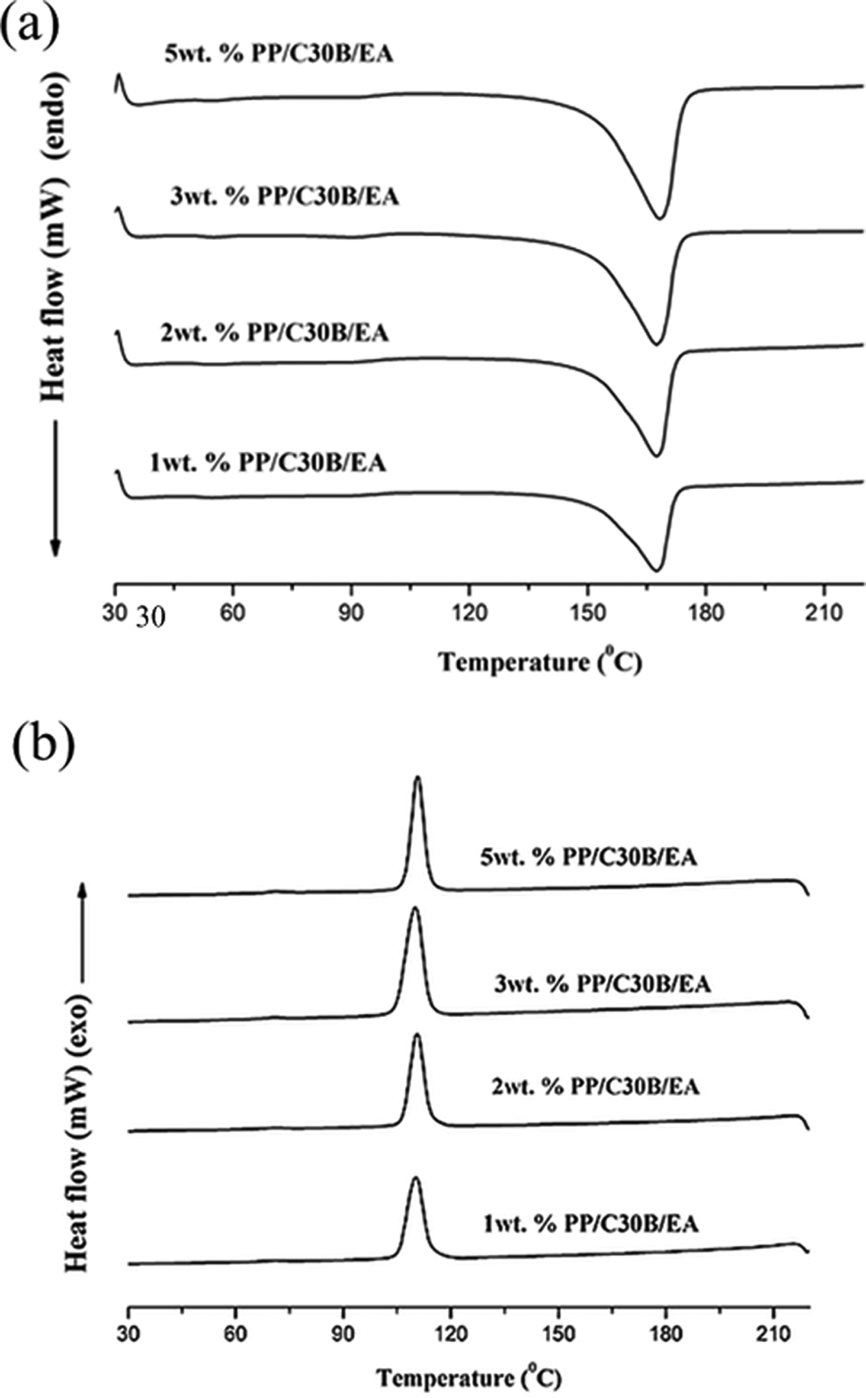
(a) DSC curves of manufactured PP/C30B/EA nanocomposites while heating in stated proportions. (b) DSC curves of manufactured PP/C30B/EA nanocomposites while cooling in stated proportions. PP: polypropylene; C30B: Cloisite 30B; EA: Elvaloy AC 3427; DSC: differential scanning calorimetry.
From the Table 3, it can be inferred that the values of T m showed only slight deviations on the processed PP/C30B/EA nanocomposites. The smallest increment in values of T m is due to the increment in lamellar thickness, which reduced the mobility of PP in the presence of C30B particles. From the graph of cooling thermograms, as shown in Figure 6(b), it was observed that the value of T c increased as the amount of C30B is increased which is due to the increase in crystallization effect. The addition of C30B to PP matrix in the presence of EA as compatibilizer acted as a nucleating agent which increased the crystallization temperature (T c). Similar kind of results was also observed by Parija et al. 37
Crystallization studies of manufactured PP/C30B/EA nanocomposites
The heat absorbed by a material during the heating depends on the crystalline nature of material. A crystalline material will absorb the heat during the entire heating and release heat, to the surroundings when it is cooled. Semi-crystalline material like PP will not be crystalline fully, but there will be a presence of the portion of the material in the amorphous state. The heat of fusion of PP material depends on the fraction of the crystalline region, and the degree of crystallinity is calculated based on the following Equation 1.
38
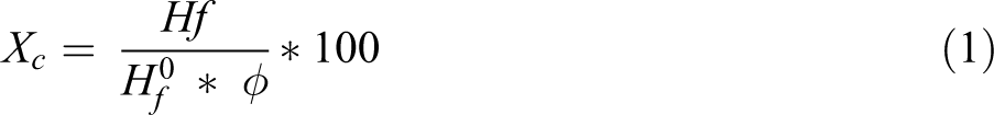
where,
(ΔHf ) – melting enthalpy of PP/C30B/EA nanocomposite specimen samples evaluated from DSC thermograms.
Φ – weight fraction of PP in PP/C30B/EA nanocomposites.
Specific melting enthalpy (ΔHf ) values decrease with the increase in C30B content which indicates that there is reduced crystallinity during the manufacturing of PP/C30B/EA nanocomposites. The values of the degree of crystallinity decreased when the C30B was increased in the PP matrix which is due to the restriction of segmental rearrangement during the crystallization process which prevents the formation of perfect crystals.
Thermogravimetric analysis of manufactured PP/C30B/EA nanocomposites
In general, nanoclays are added to the polymer matrix to increase the thermal stability by acting as a superior insulator and mass transport barriers to volatile products produced during the decomposition process as well as by supporting the formation of char after decomposition. From the past literature survey, it was found that the thermal stability of the polymers increases or decreases due to the presence of the fillers and the exact mechanism cannot be predicted (Lim et al. 39 and Sahoo et al. 40 ).
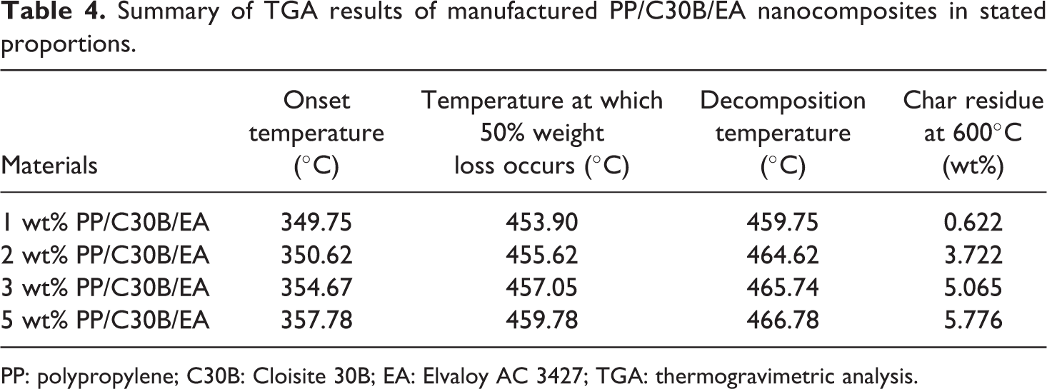
The PP/C30B/EA nanocomposite samples are heated from 30°C to 600°C at a rate of 10°C/min under nitrogen environment. The TGA curves of manufactured PP/C30B/EA nanocomposites are shown in Figure 7, and the data observed from the curves are onset temperature, the temperature at which 50% weight loss occurs, degradation temperature and char residue values at 600°C are shown in Table 4.
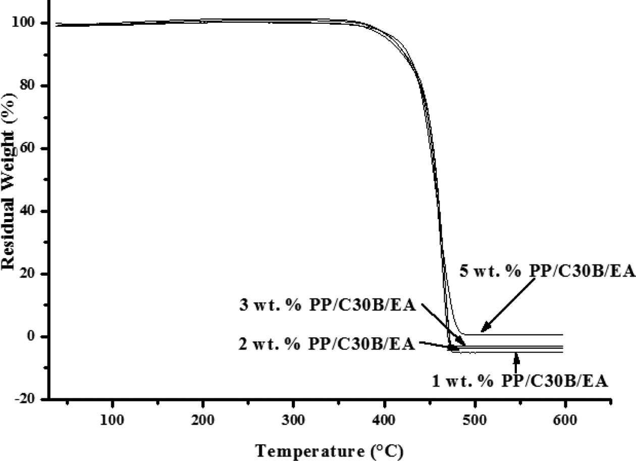
The TGA curves for manufactured PP/C30B/EA nanocomposites in stated proportions. PP: polypropylene; C30B: Cloisite 30B; EA: Elvaloy AC 3427; TGA: thermogravimetric analysis.
Summary of TGA results of manufactured PP/C30B/EA nanocomposites in stated proportions.
PP: polypropylene; C30B: Cloisite 30B; EA: Elvaloy AC 3427; TGA: thermogravimetric analysis.
There was an increase in onset temperature values from 349.75°C to 357.78°C when the addition of C30B was increased from 1 wt% to 5 wt% in PP/C30B/EA nanocomposites, which is due to the effective heat transfer between PP matrix and C30B. The temperature at which 50% degradation occurs also increased 453.90–459.78°C for 5 wt% PP/C30B/EA nanocomposites. The enhancement of the thermal stability is attributed to the strong interaction between PP polymer chains and C30B. The overall thermal stability is seen to increase with the increase in the percentage of C30B in PP/C30B/EA nanocomposites.
The temperature at which 50% weight loss occurs (°C) and the decomposition temperature (°C) are also more at 5 wt% PP/C30B/EA nanocomposites, which increases the process temperature range to an extent. The amount of char residue is more at 5 wt% PP/C30B/EA nanocomposites, which indicates that the addition of C30B at 5 wt% to the PP matrix can be thermally stable, and it will not degrade up to 600°C.
Dynamic mechanical analysis of manufactured PP/C30B/EA nanocomposites
Storage modulus of manufactured PP/C30B/EA nanocomposites
The storage modulus is the measure of stiffness or the range where there is an improvement in the elastic property. The higher amount of storage modulus indicates the improved stiffness and load-bearing capability of any material. Figure 8 shows the change in the storage modulus with the variation in temperature at 5 Hz frequency for all the additions of C30B, and the values are shown in Table 5. The storage modulus of 1 wt% PP/C30B/EA shows the storage modulus of 1327 MPa at 30°C, while the addition of 5 wt% PP/C30B/EA nanocomposites shows 1674 MPa at 30°C. There was a linear increase in the storage modulus as there was an increase in the addition of C30B. The inclusion of C30B resulted in the higher storage of PP/C30B/EA nanocomposites in the entire temperature range. The 5 wt% PP/C30B/EA nanocomposites show enhanced storage modulus when compared to all other processed PP/C30B/EA nanocomposites.
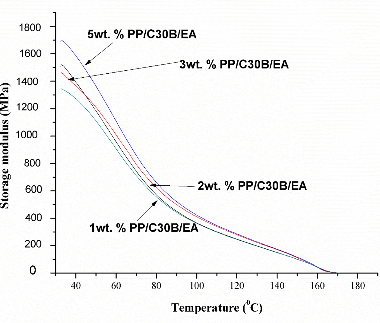
Storage modulus (MPa) versus temperature (°C) of manufactured PP/C30B/EA nanocomposites in stated proportions. PP: polypropylene; C30B: Cloisite 30B; EA: Elvaloy AC 3427.
Storage modulus (MPa) of various C30B (wt%) addition at different temperature (°C) at 5 Hz frequency.
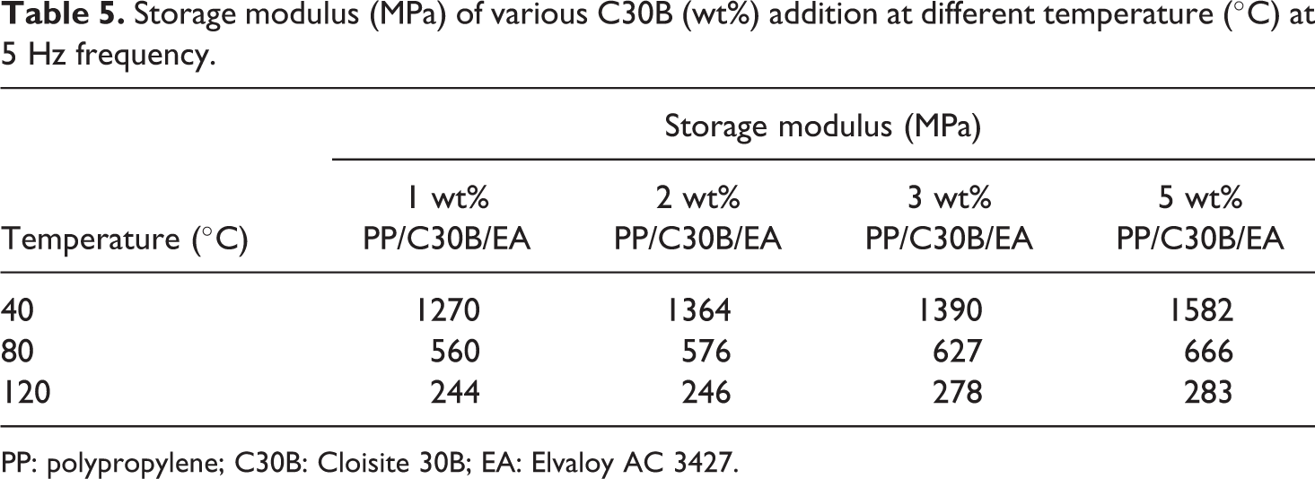
PP: polypropylene; C30B: Cloisite 30B; EA: Elvaloy AC 3427.
The temperature pattern dependence of the storage modulus of PP/C30B/EA nanocomposites was observed to be shifting from elastic behaviour to viscous with the increase in temperature. Even at 80°C, the storage modulus of 5 wt% PP/C30B/EA nanocomposites is more than 1 wt% PP/C30B/EA nanocomposites, which were similar to the previous results reported in the previous works. 23,41
The improvement in the storage modulus mainly depends on the reinforcement of C30B and the intercalation of the PP polymer chains inside C30B. When the PP was reinforced with C30B, the PP polymer interface adjacent to the C30B is restrained mechanically at the higher rate. The reinforcement of the C30B particles acts as a weak part where the stress concentration occurs. When the C30B reinforcement increases, the stress transfers between the C30B and PP matrix. The PP/C30B/EA nanocomposites’ storage modulus curves converged when it reached the melting temperature of PP.
Loss modulus of manufactured PP/C30B/EA nanocomposites
The loss modulus indicates the amount of energy lost to friction and internal motion, and it can be applied for measuring viscous component or unrecoverable oscillation energy dissipated per cycle. The finely dispersed nanoclays will dissipate energy under viscoelastic deformation. 42 Figure 9 shows the change in the loss modulus curves of 1, 2, 3 and 5 wt% PP/C30B/EA nanocomposites with the variation in temperature at 5 Hz frequency, and the loss modulus values are listed in Table 6.
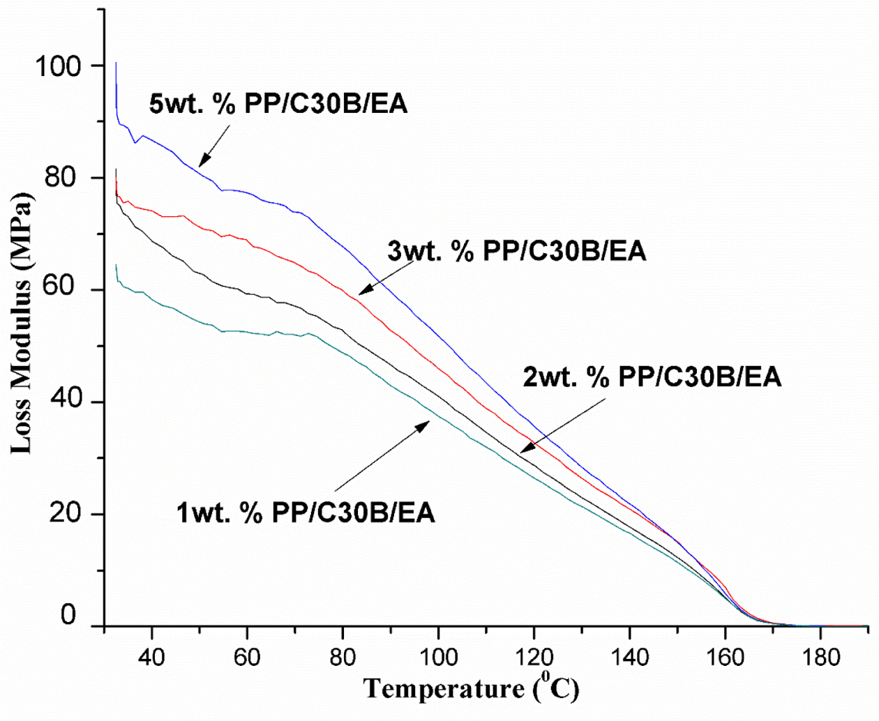
Loss modulus (MPa) versus temperature (°C) of PP/C30B/EA nanocomposites in stated proportions. PP: polypropylene; C30B: Cloisite 30B; EA: Elvaloy AC 3427.
Loss modulus (MPa) of various C30B (wt%) addition at different temperature (°C) at 5 Hz frequency.
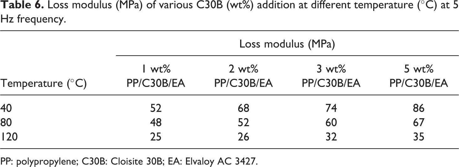
PP: polypropylene; C30B: Cloisite 30B; EA: Elvaloy AC 3427.
The value of loss modulus of 1, 2, 3 and 5 wt% PP/C30B/EA nanocomposites at 40°C is 52, 68, 74 and 86 MPa, respectively. The increase in loss modulus when the percentage of C30B is at 5 wt% in PP/C30B/EA nanocomposites is due to the agglomerated structure formation during the processing which results in the dissipation of energy in the system under viscoelastic deformation. Yang et al. 43 concluded that the value of the loss modulus increased with the reinforcement of nanoclays to polymers. Similar to storage modulus curves, the curves of the loss modulus tend to converge when PP approached the melting temperature.
Conclusion
The manufacturing of PP/C30B/EA nanocomposites was carried out using a TSE by melt intercalation method. The manufactured PP/C30B/EA nanocomposites were investigated for material characterization (metallurgical and thermal tests) The XRD of PP/C30B/EA nanocomposite showed an intercalated structure of nanocomposite category. The TEM images showed that there was a uniform dispersion of C30B in PP matrix when C30B was at 2 wt% in PP/C30B /EA nanocomposites and the agglomerated structure was formed when the percentage of C30B was at 5 wt% in PP/C30B/EA nanocomposites. DSC and TGA tests revealed that 5 wt% PP/C30B/EA nanocomposite was thermally stable than other processed PP/C30B/EA nanocomposites. The DMA studies resulted in higher values of storage and loss modulus at 5 wt% PP/C30B/EA nanocomposites.
Footnotes
Declaration of Conflicting Interests
The author(s) declared no potential conflict of interest with respect to the research, authorship and/or publication of this article.
Funding
The author(s) received no financial support for the research, authorship and/or publication of this article.