
Abstract
Ultrahigh molecular weight polyethylene (UHMWPE)/organic montmorillonite (OMMT) nanocomposites were prepared via a self-made vane mixer which could supply a synergy of ultrasound and extensional deformation. Structure and working principle of this novel mixer were illustrated in detail. Effects of the OMMT content, mixing time, and ultrasound treat time on composites’ morphology, rheological properties, and thermal properties were reported in terms of transmission electron microscopy (TEM), wide-angle X-ray scattering, differential scanning calorimetry (DSC), and thermogravimetric analysis (TGA). X-ray diffraction (XRD) and TEM showed that the OMMT lay spacing increased from 2.82 nm to 3.29 nm and OMMT dispersed evenly in the matrix using this novel melt mixing equipment. It certified that the melt mixing procedure synergized by ultrasound and extensional deformation was very effective in the exfoliation of silicate layers and also the filler distribution and dispersion. DSC measurements revealed that the crystallization temperature (T c) had no visible change with increasing the OMMT content and the melting temperature (T m) and melting enthalpy crystallinity (X c) increased with the proper OMMT content. The higher T m and X c showed with the proper ultrasound treatment time, however, the T c had no visible change. TGA showed that the onset temperature at which 20% weight loss of the material increased markedly in the case of UHMWPE/OMMT-1 wt% nanocomposite. The onset temperature slightly decreased with the use of ultrasound. Rheological analyses showed that all the samples exhibited non-Newtonian and shear thinning characteristics. Both the storage modulus and complex viscosity increased with continuous addition of the OMMT layers. It also indicated that the introduction of ultrasound tended to decrease the storage modulus and complex viscosity. Universal tensile test indicated that superior tensile strength occurred in samples containing OMMT layers.
Keywords
Introduction
Ultrahigh molecular weight polyethylene (UHMWPE) is an excellent overall performance engineering thermoplastics and engineering plastics 1 owing to its properties including high toughness, good chemical stability, low friction coefficient, and minimal water absorption. 2 Although UHMWPE possesses many excellent properties but its poor adhesion to fillers, lower thermal stability, high melt viscosity, and creep are the main hurdles for its vast spread engineering applications. 3 In order to improve these properties, inorganic particles were often used as reinforcement or filler materials. 4,5 Clay–polymer nanocomposites have recently attracted a great deal of attention as they offer enhanced mechanical and thermal properties when compared to the pure polymer. 6,7 The organic montmorillonite (OMMT) clay is commonly used to prepare the clay–polymer nanocomposites due to low cost and easy processing. The most serious factor that governs the final development in the properties of polymer/OMMT nanocomposites is the level of dispersion, exfoliation, and intercalation of the nanoclay in the nanocomposite. Because of the strong electrostatic attraction between the silicate layers and the intergallery cations, it is difficult to achieve complete exfoliation of montmorillonite in a continuous polymer matrix. Many researchers have shown that nanofillers can be incorporated into UHMWPE matrix via in situ polymerization, 8 solution casting, 9 and melt mixing 10,11 to improve thermal, mechanical, electrical, UHMWPE-filler adhesion, fluidity, and reduce flammability of the pristine UHMWPE.
It is widely believed that the mixing process dominated by extensional deformation has various advantages such as better dispersive and distributive mixing, reduced melt temperature, wide adaptability, and so on. 12 And also the ultrasonic waves in the liquid medium are known to generate cavitation events where numbers of microbubbles are created which grow due to the pressure fluctuations and collapse adiabatically over a very small time scale. 13 The ultrasonic cavitation has been also reported to help in the separation of silicate layers into the number of exfoliated platelets due to microstreaming phenomena. 14,15
The main objective of this research is to develop a novel mixer which was synergized by ultrasound and extensional deformation based on our previous research results 16 to help in exfoliation and homogeneous dispersion of clay into the matrix. We prepared UHMWPE/OMMT composites using this novel ultrasound-assisted vane mixer (UAVM). And also effects of OMMT content and ultrasonic treatment time on the properties of OMMT/UHMWPE composites were reported.
Experimental
Ultrasound-assisted vane mixer
The schematic diagram of the ultrasound-assisted melt mixing machine used in the experiment was shown in Figure 1. From Figure 1, we can see that the mixer is mainly composed of one feeding unit and one mixing unit. The feeding unit composed of a stator, four short vanes, and part of the rotor. The structure and working principle of the unit was introduced in detail in our previous study. 17
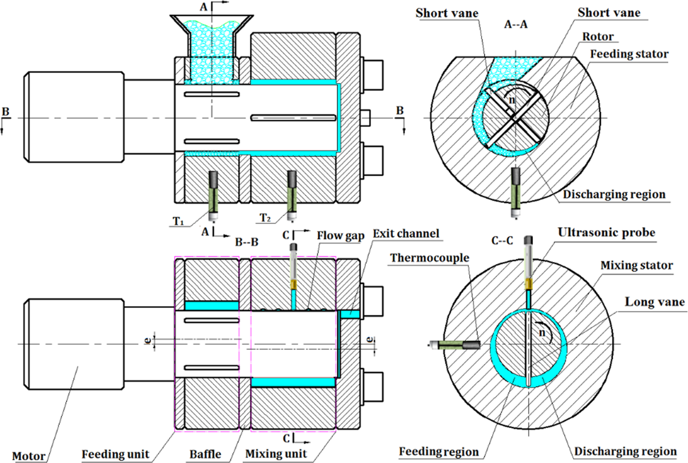
Schematic drawing of the UAVM.
The mixing unit composed of one stator, one long vane, and rotor. As shown in Figure 1 (C–C), the rotor is eccentrically installed in the inner hole of the stator. The long vane is installed in the rectangular through hole of the rotor. The vanes make reciprocating movement in the rectangular through hole of the rotor under the action of the inner surface of the stator as the rotor rotates. This action leads to the periodical changing of the volume constituted by the stator, rotor, vane, and non-return baffle. The region where the volume decreases is called discharge region. On the contrary, the region where the volume increases is called feeding region (Figure 1, C–C). There are five circular flow gaps (Figure 1, B–B and Figure 1, C–C) on the inner surface of the stator which connected the discharge region and the feeding region. Cycle flow was generated between the discharge region and the feeding region as the rotor rotates. Dynamic extensional flow is generated by the dynamic convergent and divergent flow as the geometry of the mixing chamber changes periodically. The convergent and divergent flows are expected to contribute significantly to dispersive mixing. As shown in Figure 1 (C–C), an ultrasonic probe is installed in the discharging region of the mixing unit. The ultrasonic horn (10-mm diameter at tip) contacts with the polymer melt directly, providing mechanical vibrations perpendicular to the melt flow direction. In this way, a melt mixing synergized by ultrasound and extensional deformation is carried out.
Materials
UHMWPE in the powder form was used. UHMWPE resin with a molecular weight of 2.6 × 10⁶ g mol−1 and a mean particle size of about 190 μm was provided by Shanghai Research Institute of Chemical Industry (Shanghai, China).
The alkyl ammonium surface–modified OMMT (trade name: I.44p) was purchased from Nanocor (Aberdeen, Mississippi, USA).
Sample preparation
Prior to processing, UHMWPE resin and OMMT were dried at 80°C in a vacuum oven for at least 8 h. Dried UHMWPE powder and OMMT (the content is 0, 1, 3, and 5 wt%, respectively) were manually premixed by tumbling in a plastic ziplock bag and subsequently fed into the UAVM for melt compounding. The total mass of UHMWPE/OMMT composite is 20 g. The rotor speed fixed at 40 r/min, while the mixing time was set as 4 min.
The ultrasonic frequency and power used in the fabrication was 10 kHz and 1000 W, respectively. The supersonic generator comes into operation after mixing for 2 min (to ensure the UHMWPE completely in molten state) and continued for 5, 10, 15 and 20 s, respectively. The temperature of the feeding unit and the mixing chamber was set at 230°C. The nanocomposites were forced out from the outlet channel when the mixing procedure finished. In all cases, materials were cooled to room temperature in water and subsequently granulated by a pelletizer.
Characterization
Morphology observation
Transmission electron microscopy (TEM) observations were carried out using a JEM-1400 Plus (JEOL, Japan) at an acceleration voltage of 120 kV. Ultrafine sample cuts were prepared with a thickness of 70 nm using a Leica EMUC6/FC6 microtome (Leica, Germany).
Wide-angle XRD
D8 ADVANCE (Bruker, Germany; copper K α, λ = 0.154 nm, 40 kV, 40 mA) was used for wide-angle XRD (WAXD) analysis of the UHMWPE/OMMT nanocomposites. The measurement was performed at a 2θ angle of 1–10°, a scanning rate of 2° min−1, and a scanning step of 0.02°. To obtain a clear X-ray scattering intensity, a cubic patch with a width of 4 mm, a length of 10 mm, and a thickness of 1 mm was carefully processed from the compression mold specimens.
Differential scanning calorimetry
Thermal properties of UHMWPE/OMMT composites were evaluated with a NETZSCH DSC204 (Germany) differential scanning calorimeter. The samples weighted about 5 mg were sealed in an aluminum pan and heated or cooled in a nitrogen atmosphere. At first, the samples were heated from room temperature to 180°C at a rate of 10°C min−1 to erase the thermal history and cooled at a rate of 10°C min−1 to obtain the non-isothermal crystallization. Then, the second heating run followed at a heating rate of 10°C min−1.
Thermogravimetric analysis
A Netzsch TG209 thermogravimetric analyzer (Germany) was used to analyze the thermal stability of UHMWPE/OMMT composites. The weight of the samples was approximately 10 mg. The analyses were done from 30°C to 600°C at a heating rate of 10°C min−1 under nitrogen flow (20 ml min−1).
Rheological properties analysis
Dried composite pellets were compression-molded at 200°C for 15 min and disk-shaped specimens with a thickness of 1 mm and a diameter of 25 mm were prepared. Physica MCR302 rheometer from Anton Paar (Austria) equipped with a CTD620 convection oven was used to measure the dynamic rheological behavior of the UHMWPE/OMMT samples. The samples were tested at 190°C with a scanning frequency range of 100–0.01 rad s−1 and strain amplitude of 1%. All tests were run under nitrogen purge at a flow rate of 5 mL min−1.
Mechanical test
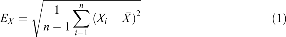
The dried composite pellets were compression-molded into flat plate with thickness of 1 mm using a flat plate sulfide machine (QLB-25D/Q) at 200°C for 15 min. Flat plates were cut into standard dumb-bell–shaped tensile test specimens. Tensile test was conducted using an INSTRON universal machine (model 5566, Instron, USA) with a tensile speed of 10 mm min−1 according to the GB/T 1447–2005 standard. All tests were performed at ambient temperature (25°C), and five specimens were used in each test (Xi
) to obtain the average value (
Results and discussion
Morphology of the nanocomposites
WAXD is an important tool in revealing two-dimensional nanofillers’ nanostructure due to the WAXD could determine the layer spacing of fillers’ layer. Thus, WAXD was employed to show the nanostructure of the OMMT. Figure 2 shows the WAXD patterns of the UHMWPE/OMMT nanocomposites with different OMMT concentration and ultrasound treatment time. The basal distances are calculated by Bragg’s law (λ = 2dsinθ, where d is the layer spacing and λ is the X-ray wavelength).
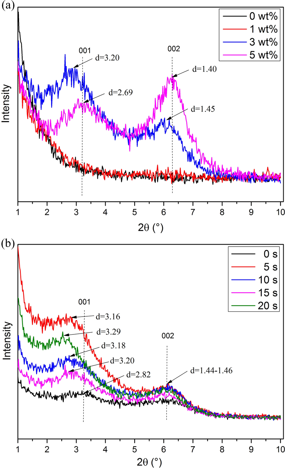
WAXD curves of the UHMWPE/OMMT nanocomposites in (a) different OMMT contents and (b) different ultrasound treatment times.
The WAXD patterns of UHMWPE/OMMT nanocomposites with different OMMT contents were shown in Figure 2(a). (The ultrasound treatment time was constant at 15 s.) As shown in the patterns, when the OMMT content is 1 wt%, the (001) plane peaks of the nanocomposites disappeared in the WAXD curve. This may correspond to either the exfoliated dispersion state or simply to the low content of the used clay. 18,19 When the content of the OMMT increased from 3 wt% to 5 wt%, the (001) plane peaks of nanocomposites increased from 2.756°to 3.280°, which correspond to a basal spacing of 3.20 nm and 2.69 nm, showing that the interlayer distances were lessened. This indicates that the OMMT was better dispersed when the content is lower. 20
The WAXD patterns of UHMWPE/OMMT nanocomposites of different ultrasound treatment times are shown in Figure 2(b). (The OMMT content was fixed at 3 wt%.). As shown in Figure 2(b), the (001) plane peaks of nanocomposites were shifted to lower angles with the increase of ultrasound treatment time, indicating the fact that the ultrasound helped in the separation of silicate layers.
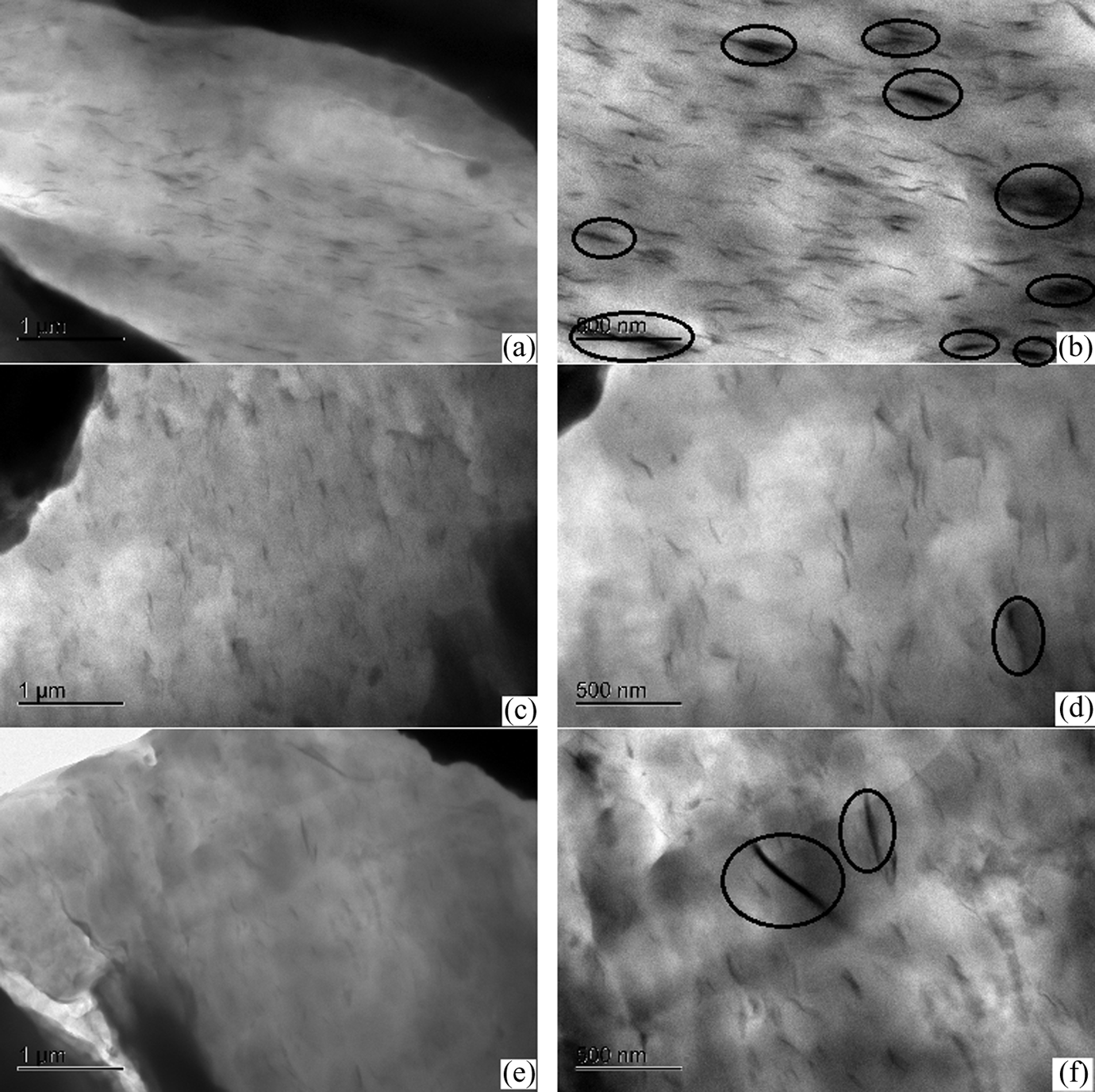
Figure 3 shows the TEM images of UHMWPE/OMMT nanocomposites with different OMMT concentrations under ultrasound treatment of 15 s. The dispersion and exfoliation morphology of the OMMT layers in the UHMWPE matrixes is shown in Figure 3(a) to (e). In the figure, it can be found that the OMMT layers are uniformly dispersed in the UHMWPE matrixes and the dimension of the OMMT is smaller when the OMMT content is lower. No large lamellar observed even the OMMT content is 5% at such a short mixing time (4 min). As shown in Figure 3(b) to (f), the intercalation and exfoliation nanostructures of the OMMT in the UHMWPE can be observed clearly. Most of the OMMT layers are exfoliated and intercalated into individual platelets when the OMMT loading level is less than 3 wt%, as shown in Figure 3(b) and (d). The intercalation and exfoliation of the OMMT layers are observed when the OMMT content is 5 wt%; however, we could also observe that there is obvious aggregation of OMMT, as shown in Figure 3(f). This is consistent with WAXD result that the OMMT was easily exfoliated and intercalated in the nanocomposite and better dispersed when the content is relatively lower.
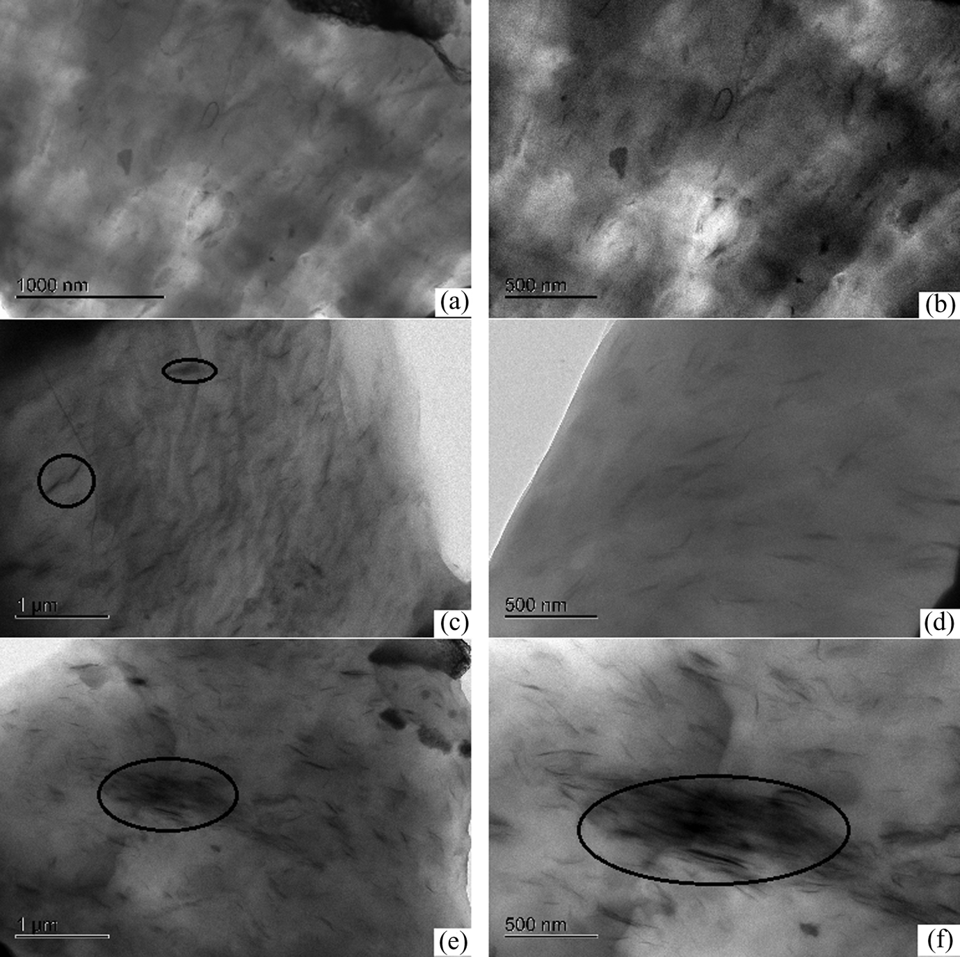
Low and high magnification TEM image of UHMWPE/OMMT nanocomposites with different OMMT contents: (a) and (b) 1 wt%, (c) and (d) 3 wt%, and (e) and (f) 5 wt%.
Figure 4 shows the TEM images of UHMWPE/OMMT nanocomposites with a fixed OMMT content of 3 wt%. As shown in Figure 4(a) to (e), the clay platelets were well dispersed in the polymer matrix. The d-spacing of the layers increased from 2.82 nm to 3.16 nm with the increase of ultrasound treatment time. This phenomenon further confirmed the fact that the ultrasound helped in the separation of silicate layers.
Low and high magnification TEM image of UHMWPE/OMMT nanocomposites with different ultrasound treatment times: (a) and (b) 5 s, (c) and (d) 10 s, and (e) and (f) 20 s.
Differential scanning calorimetry analysis
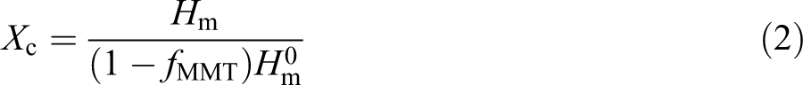
The effect of OMMT content on the composites’ thermal properties was shown in Figure 5. Detail information of the differential scanning calorimetry (DSC) analysis was summarized in Table 1 which shows T c, T m, heat of crystallization (▵H c), heat of melting (▵H m), and X c of the UHMWPE/OMMT composites. The X c of the UHMWPE phase is calculated according to equation (2) 21 :
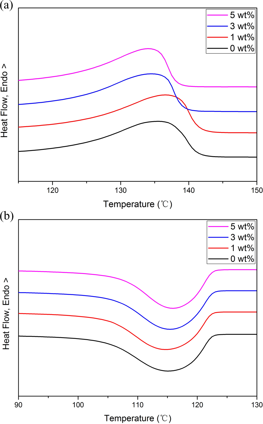
DSC melting curves of UHMWPE/OMMT composites with different OMMT contents in (a) second heating and (b) cooling.
DSC parameters of melting and crystallization for samples of different OMMT contents (second heating cycle).
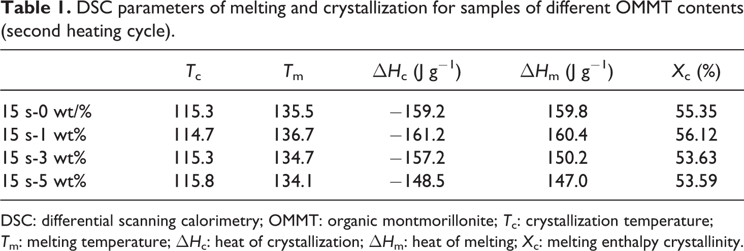
DSC: differential scanning calorimetry; OMMT: organic montmorillonite; T c: crystallization temperature; T m: melting temperature; ▵H c: heat of crystallization; ▵H m: heat of melting; X c: melting enthalpy crystallinity.
where f
MMT is the mass fraction of OMMT in the composites and
From Figure 5 and Table 1, we can find that the T c had no visible change with increasing the OMMT content in the matrix. T m and X c first rise up and then decrease with the increase in OMMT content. The crystallization kinetics of polymer is a complicated process that involves two important steps: nucleation and diffusion of crystallizable chains to the crystal front. On the one hand, there could be the nano-reinforcement effect of OMMT layers together with the intercalation agent, which were dispersed in the continuous UHMWPE matrix and could restrict the motion of polymer chains and thus give rise to the decrease in X c. On the other hand, the dispersed silicate layers in the matrix might serve as nucleation seeds that could induce some additional crystallinity. 23 From Figure 5, we can find a decrease in width in the half height of the peak with the increase in OMMT loading showing the uniformity in crystallite size distribution. 24
The effect of ultrasound treatment time on composites’ thermal properties was studied and shown in Figure 6. Results of the DSC analysis were summarized in Table 2. From Figure 6 and Table 2, we can find that the T c had no visible change with increasing the ultrasound treatment time. T m and X c firstly increased and then decreased with the increase in ultrasound treatment time. From the XRD and TEM results, we demonstrated that the ultrasonic irradiation induced a better dispersion of the OMMT in the matrix. And the better dispersion could result in the higher nucleation efficiency of OMMT and the stronger interaction of OMMT and UHMWPE. 25 As stated above, the crystallization kinetics of polymer is a complicated process that involves two important steps: nucleation and diffusion of crystallizable chains to the crystal front. Therefore, the better dispersion of the OMMT results in two contrary effects on the crystallization kinetics of UHMWPE.
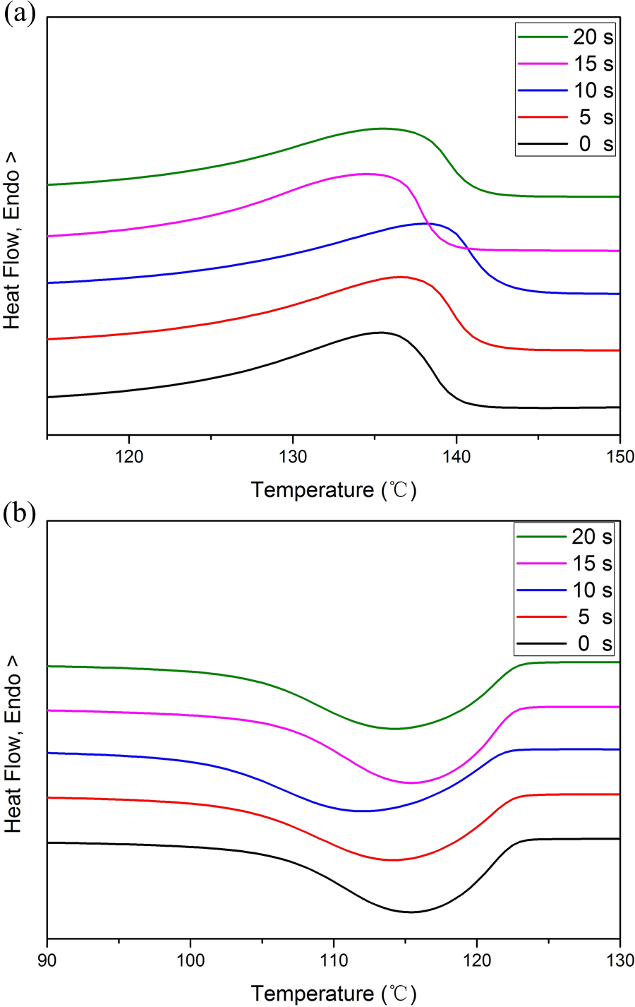
DSC melting curves of UHMWPE/OMMT composites with different ultrasound treatment times in (a) second heating and (b) cooling.
DSC parameters of melting and crystallization for samples of different ultrasound treatment times (second heating cycle).
DSC: differential scanning calorimetry; T c: crystallization temperature; T m: melting temperature; ▵H c: heat of crystallization; ▵H m: heat of melting; X c: melting enthalpy crystallinity.
Thermogravimetric analysis
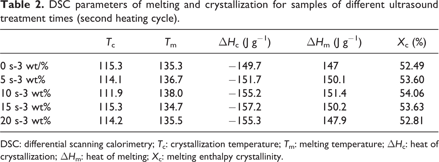
The thermal stability is an important property for which the nanocomposite morphology plays a significant role. The thermogravimetric analysis (TGA) plots as obtained from the UHMWPE and UHMWPE/OMMT nanocomposite have been shown in Figure 7(a) and (b), respectively. It can be clearly seen from the TGA plots shown in Figure 7(a) that the onset temperature at which 20% weight loss of the material occurs obviously increased in the case of UHMWPE/OMMT-1 wt% nanocomposite as compared to the pristine UHMWPE. It is plausible that the OMMT migrates to the surface, forming a protecting barrier that impedes the release of gases from the decomposition, increasing the degradation temperature of the material. 26 From Figure 7(b), we can find that the onset temperature at which 20% weight loss of the material occurs slightly decreased with the use of ultrasound. Similar result can be found in other research. 25 It is plausible that the thermal stability decreased under the effect of ultrasonic degradation. 26 Therefore, we can conclude that UHMWPE/OMMT-1 wt% without ultrasonic treatment gives the best thermal stability in the composites.
TGA plots of UHMWPE/OMMT composites with (a) different OMMT and (b) different ultrasound treatment times.
Rheological properties analysis
The parallel disc oscillatory shear test is a kind of small amplitude deformation test, which does not change the material structure. In this work, we use it to characterize the relation between the materials’ rheological properties and the frequency.
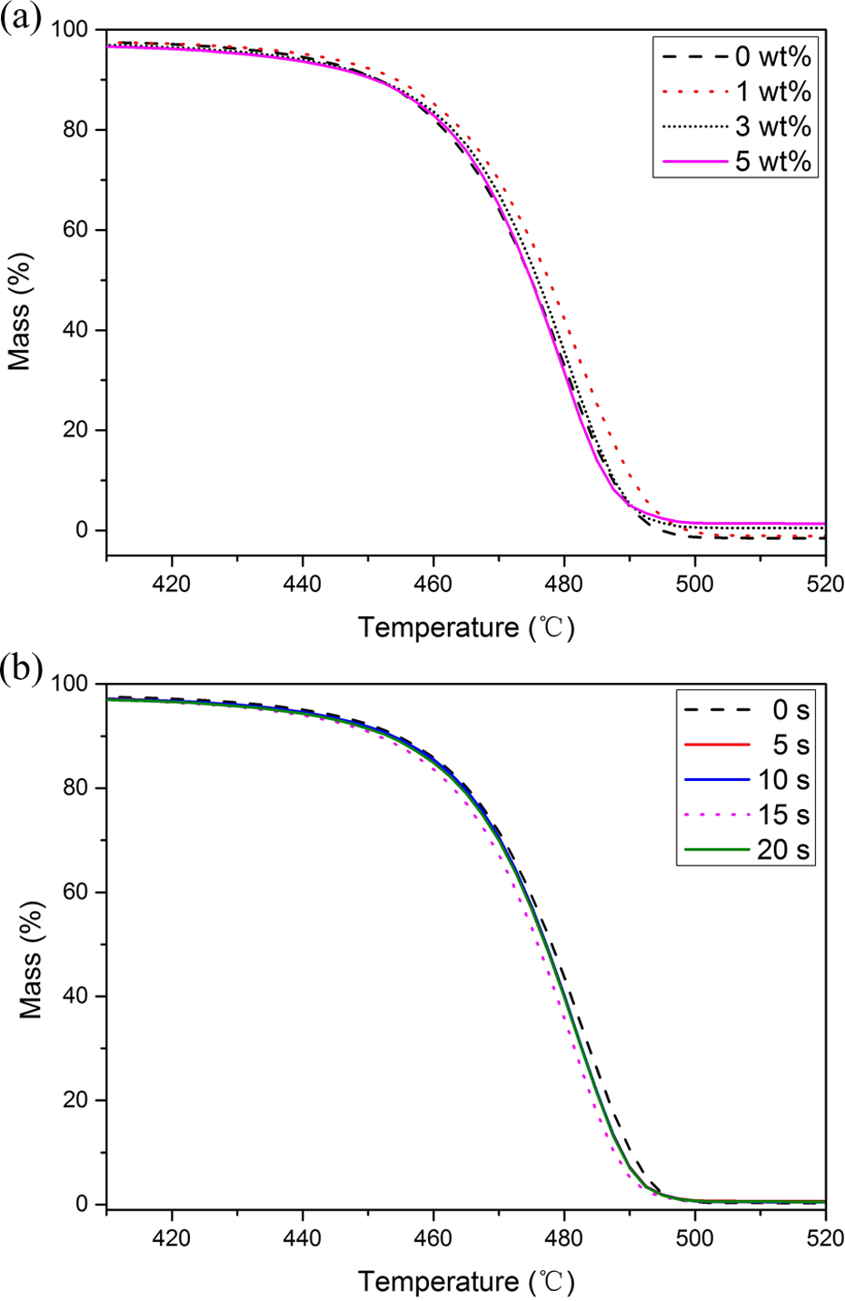
Figure 8(a) and (b) shows the variation of storage modulus versus angular frequency of UHMWPE/OMMT nanocomposites with increasing OMMT loading and ultrasound treatment time, respectively, at 190°C. In the case of increasing OMMT content in UHMWPE/OMMT nanocomposites, the ultrasound treatment time was set as 15 s. With the increase of ultrasound treatment time, the content of OMMT was fixed at 3 wt%. As shown in Figure 8(a), the slope of curve in low-frequency region becomes smaller with increasing OMMT, and the storage modulus of UHMWPE is obviously increased when the OMMT was added. This is because the OMMT was dispersed in the continuous UHMWPE matrix and could restrict the motion of polymer chains and thus gives rise to the increase in storage modulus. As shown in Figure 8(b), the storage modulus of UHMWPE is slightly decreased with the use of ultrasound, especially in the low-frequency region.
Storage modulus of UHMWPE/OMMT composites with (a) different OMMT and (b) different ultrasound treatment times.
Figure 9(a) and (b) shows the variation of complex viscosity versus angular frequency of UHMWPE/OMMT nanocomposites with increasing OMMT content and with increasing ultrasound treatment time, respectively, at 190°C. From Figure 9(a), we can find the complex viscosity of UHMWPE is obviously increased when the OMMT was added, especially in the low-frequency region. This result could be attributed to the polymer chains of UHMWPE that intercalate into the organoclay layers and increase the gallery distance after melt blending, and the percolated nanostructure has been formed in the nanocomposites. 27 From Figure 9(b), we can find the complex viscosity of UHMWPE is slightly decreased with the use of ultrasound. As stated in TGA result, this is due to the effect of ultrasonic degradation.
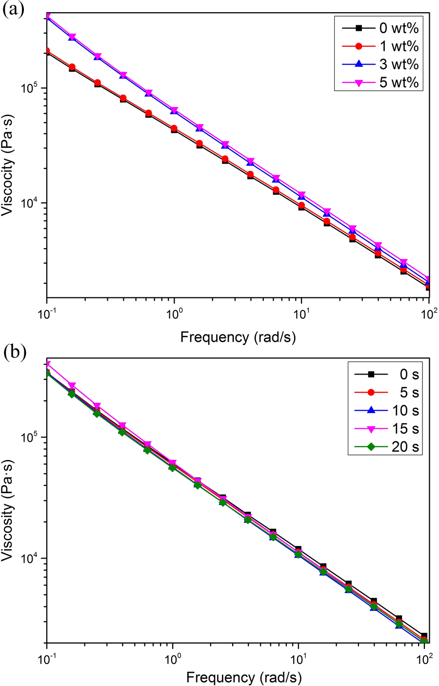
Complex viscosity of UHMWPE/OMMT composites with (a) different OMMT and (b) different ultrasound treatment times.
Tensile properties
Figure 10(a) and (b) shows the variation of tensile strength versus OMMT content and ultrasound treatment time of UHMWPE/OMMT nanocomposites, respectively. In the case of increasing OMMT content in UHMWPE/OMMT nanocomposites, the ultrasound treatment time was set as 15 s. With the increase of ultrasound treatment time, the content of OMMT was fixed at 3 wt%. From Figure 10(a), we can find the tensile strength of the nanocomposites is obviously increased when the OMMT was added. Furthermore, the slope of curve becomes obviously smaller with increasing OMMT content. It may be due to that the OMMT is dispersed in UHMWPE matrix on the nanometer scale and most of OMMT are intercalated by the polymer chain of UHMWPE, which corresponds to the formation of percolated nanostructure in the UHMWPE/OMMT nanocomposites, resulting in a corresponding increase in mechanical properties. 27 As discussed earlier, the dispersion of the OMMT in 1 wt% is better than that in 3 wt% and 5 wt%. Therefore, the slope of curve (Figure 10(a)) becomes obviously smaller with increasing OMMT content, indicated that the reinforce efficiency of OMMT decreased when the OMMT content increased. However, with the increase in OMMT content, the tensile strength of the nanocomposites increased obviously. From Figure 10(b), we can find the tensile strength of the nanocomposites slightly decreased with the introduction of ultrasound. There are two possible reasons that cause these phenomena. On the one hand, from the XRD and TEM results, we know that the ultrasonic irradiation induced a better dispersion of the OMMT. On the other hand, it was reported that the ultrasound can shorten molecular chain 26 and lead to reduction in tensile strength. Therefore, due to the enhancement function of OMMT and the effect of ultrasonic degradation, the tensile strength of the nanocomposites slightly decreased.
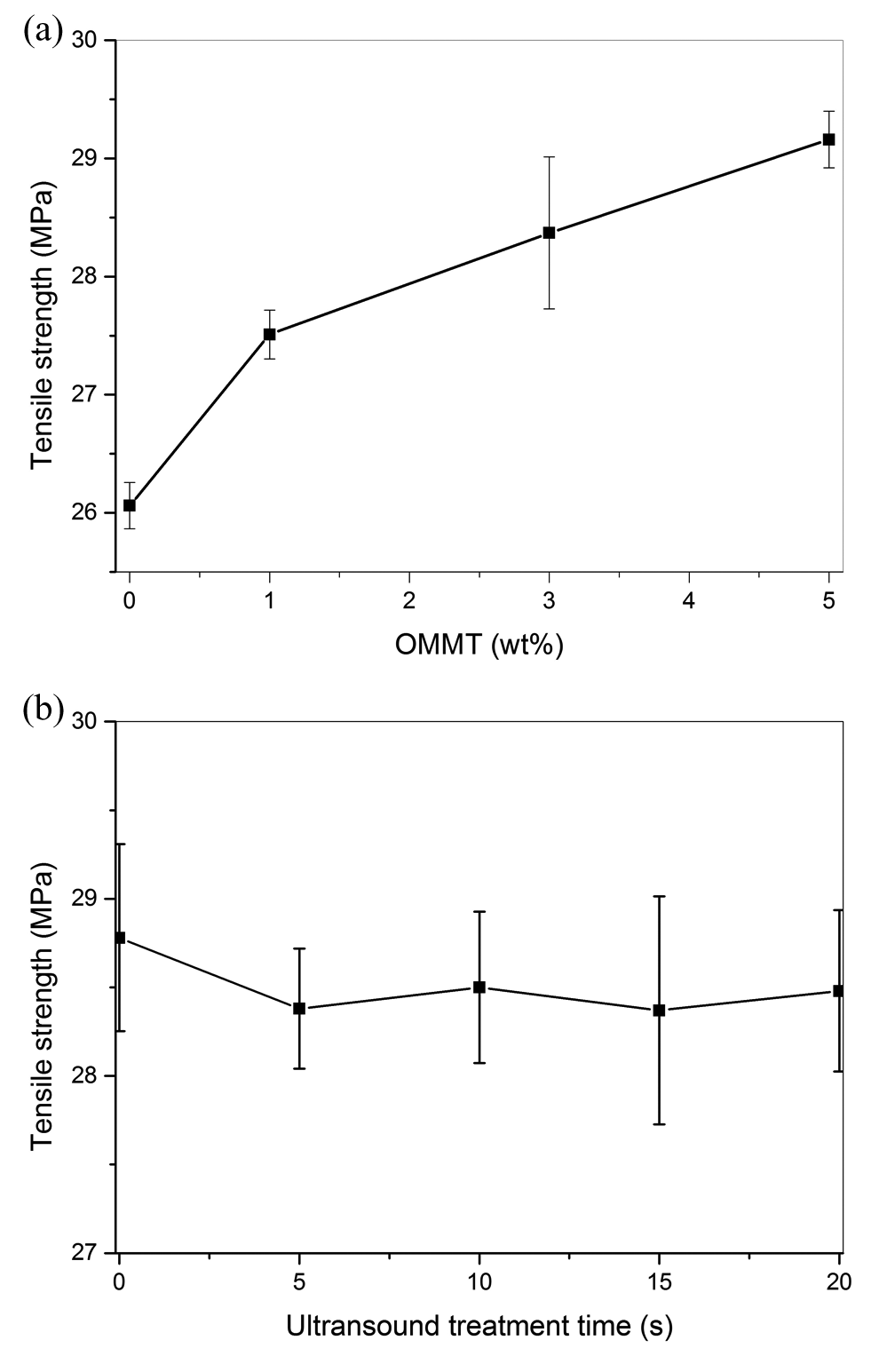
Tensile strength of UHMWPE/OMMT composites with (a) different OMMT and (b) different ultrasound treatment times.
Conclusions
We prepared the UHMWPE/OMMT nanocomposites via a novel UAVM and investigated the effects of OMMT content and ultrasonic treatment time on the properties of UHMWPE/OMMT composites. XRD and TEM measurements revealed that the introduction of ultrasound leads to the more exfoliated, smaller intercalated OMMT and improved dispersion of OMMT in UHMWPE/OMMT nanocomposites. DSC measurements revealed that the T m and X c of UHMWPE/OMMT nanocomposites increased with the proper OMMT content. With the introduction of ultrasound, T m and X c of UHMWPE/OMMT nanocomposites increased with the proper ultrasound treatment time. TGA indicated that the thermal stability of the material obviously increased with proper OMMT content. However, the thermal stability slightly decreased with the introduction of ultrasound due to the effect of ultrasonic degradation. Rheological results showed that all samples exhibit non-Newtonian and shear thinning characteristics. The storage modulus and complex viscosity both increased with the increase of the OMMT content. The introduction of ultrasound tended to decrease the storage modulus and complex viscosity. The mechanical test results showed that the tensile strength of the nanocomposites is obviously increased when the OMMT was added. However, with the introduction of ultrasound, the tensile strength of the nanocomposites slightly decreased.
Footnotes
Acknowledgements
We acknowledge the National Key Research and Development Program of China, the Key Program of National Natural Science Foundation of China, the National Natural Science Foundation of China-Guangdong Joint Foundation Project, Special Support Program of Guangdong Province, Natural Science Foundation of Guangdong Province, China, and Science and Technology Program of Guangzhou, China.
Declaration of Conflicting Interests
The author(s) declared no potential conflicts of interest with respect to the research, authorship, and/or publication of this article.
Funding
The author(s) disclosed receipt of the following financial support for the research, authorship, and/or publication of this article: This work was financially supported by the National Key Research and Development Program of China (grant no. 2016YFB0302302), the Key Program of National Natural Science Foundation of China (grant no. 51505153), the National Natural Science Foundation of China-Guangdong Joint Foundation Project (U1201242), Special Support Program of Guangdong Province (no. 2015TX01X151), Natural Science Foundation of Guangdong Province, China (no. 2016A030313004), and Science and Technology Program of Guangzhou, China (no. 201607010240).