
Abstract
Experiments were carried out to study the dripping behavior of vertical burning thermally thin poly(methyl methacrylate) (PMMA) with different spacings between the wall and PMMA. The dripping behavior was studied by infrared video image analysis with spacings of 7, 10, 13, 16, 19, 22, and 25 mm. As the spacing increased, the dripping time and mass and burnout growth distance first increased and then decreased. The critical value was observed at the 13 mm case. The dripping behavior is assumed to correspond to the net heat flux to the surface, extensional viscosity, and gravitational force of melting PMMA. After the dripping, the pyrolysis and burnout spread rates become asymptotically equal.
In this study, the effects of spacing between the wall and fuels on the dripping behavior were investigated for the first time using uniform PMMA samples with 200 mm height, 50 mm width, and 2 mm thickness.
Keywords
Introduction
Thermoplastic poly(methyl methacrylate) (PMMA), one of the best organic synthetic materials, has been widely used in various aeronautical applications. Owing to their exceptional transparency, shape adaptability, low density, and high impact strength, they find particular attention in the aerospace industry where thermally thin PMMA materials are used to manufacture aircraft canopies, windshields, impact resistant windows, visors, and safety glasses. 1 Therefore, many damageable objects are protected by large thermally thin PMMA materials. However, the potential hazards of these thermoplastics in fires are a matter of great concern. For instance, the dripping of burning polymers has been recognized as a great threat to the public, which can accelerate fire growth and spread fires between nonadjacent objects. When thermally thin PMMA materials are set in a vertical orientation, the molten materials drip because of the high mobility triggered by increasing temperature. 2
In the fire research community, many researchers 2 –8 investigated the dripping behavior of burning thermoplastic materials. Wang et al. 2 –4 carried out small-scale experiments for the dripping behavior of PMMA under the UL94 vertical test conditions. 9 The results indicate that flame spread and burning rate affect the dripping behavior of thermally thin PMMA materials. Under the UL94 vertical test conditions, the dripping behavior was categorized into two different types: (i) small and uniform drops with a short first dripping time and (ii) large and irregular drops with a long first dripping time. The activation energy of viscous flow and the ratio of the effective heat of combustion to the heat of gasification were also important properties of materials dominating the dripping types of polymers. 2 Regarding the factors influencing the dripping, it can be attributed to the reduction of viscosity not only due to physical melting but also due to chemical degradation. 2,3,7 . Xie et al. 5 demonstrated that a thinner thermoplastic sheet dropped faster and reached the peak heat release rate earlier than a thicker thermoplastic sheet. A thermally thick PMMA sheet exhibited softening, distortion, and surface bubbling; however, no dripping of the melted polymer was observed during the test by Zhang et al. 6 Kandola et al. 8 established the relationships between the glass transition temperature and melt viscosity with the dripping behavior and burning intensity of PMMA.
All the studies mounted the polymer on a wall 5,6 or suspended 2,3,8 and subjected to a source of fire at the bottom during the tests. However, they did not consider the actual situation. Sometimes, the thin PMMA material is not completely attached to the wall, and a spacing exists between the wall and PMMA as shown in Figure 1. When thermally thin PMMA materials in a vertical orientation were ignited at the bottom in this case, an upward flame spread was observed on the front side, and the backside flame became one of the most important modes of parallel combustion between the backside of the sample and the wall.
Spacing effect on upward flame spread model. (a) Before dripping and (b) after dripping.
As the spacing between the wall and fuels increased, the physical picture gradually changed by the following effects: 10 a fraction of the net heat flux to the surface from the back flame increased, the scale of the turbulent eddies increased by the wall, and the flow of oxygen available for the combustion in the gap increased. Although these effects influenced the rate of fuel production by the wall, the net effect associated with dripping behavior of burning PMMA is not very clear.
As shown in Figure 1, the front flame height of PMMA is Xff, the back flame height is Xfb, the pyrolysis height is Xp, and the burnout length is Xb. The length of the pyrolysis zone is Lp (Lp = Xp − Xb). Fuel vapors are released from the pyrolysis surface and participated in the flame, which is confined to the buoyancy-induced boundary layer. The regions (Xff − Xp) and (Xfb − Xp), where the flame extends beyond the pyrolysis length, are known as the combusting plume region, and the heat transferred from this region to the virgin fuel above Xp is responsible for the upward spread of the flame. 11 A thermally thin PMMA material was used as the sample to investigate the effects of spacing on the dripping behavior. Thermally thin materials have unique properties: thermally thin flues are assumed to have no spatial and internal temperature gradients and the physical thickness, d, should be less than the thermal penetration depth: 12
where d is the physical thickness of the fuel, δT is the thermal penetration depth, α is the thermal diffusivity, t is the time, k is the conductivity, Ts is the surface temperature, T0 is the initial temperature, and
In this study, a series of experiments for thermally thin PMMA (H is the height of 200 mm, W is the width of 50 mm, and d is the thickness of 2 mm) were carried out to compare the characteristics of the dripping behavior of vertical burning thin PMMA material with different spacings to the wall in the laboratory. By increasing the spacing b between the wall and PMMA, the dripping time td, dripping mass md, burnout growth distance ΔXb, surface temperature during the dripping Td, and pyrolysis spread rate Vp were investigated.
Because the dripping behavior plays an important role in the fire hazards of thermoplastic PMMA materials, it is necessary to investigate the properties of dripping behavior with different spacings. To the best of our knowledge, the effects of spacing between the wall and fuels on the dripping behavior of burning thermally thin PMMA material have not been reported.
Experimental setup
A range of experiments were designed to study the dripping behavior of a vertical burning thermally thin PMMA material with different spacings to the wall. A schematic of the experimental apparatus is illustrated in Figure 2.
Schematic of the experimental apparatus.
The experimental apparatus contained a vertical sample of clear PMMA with 200 mm in height, 50 mm in width, 11,13 and 2 mm in thickness. The tests were carried on the same type of PMMA with the same parameters such as the ignition temperature and density, thus reducing the experimental error and flame fluctuation. 14 The samples were covered with two metal plates, and a wall (Marinite board [calcium silicate boards]) was placed behind the samples. In this study, the sample width was fixed at 50 mm to minimize the amount of variance between the tests because a smaller sample size may affect the amount of combustible gases generated by the fuel owing to a significant diffusion of the fuel to the sides of the sample. 11,15 A Marinite board with 350 mm height, 90 mm width, and 20 mm thickness was used as the vertical wall. They were mounted on an aluminum sheet holder with four screws as shown in Figure 2. Four groups of spacers were installed between the wall and fuels to maintain a distance and to ensure that the fuel was parallel to the wall. The experimental apparatus was hung by two load cells, with an accuracy of ±0.01 g and 22 kg capacity, which were used to measure and record the mass loss from the samples at half-second intervals during the test. A high definition (HD) digital camcorder recording at 20 frames per second was set at the side of the samples to obtain a side view of the front and back flame heights. The flame height was defined by the average value of 20 frames. The progress of the pyrolysis front was determined by analyzing the infrared video recordings of each experiment set at the front of the fuels. The sketch map of the setup is shown in Figure 3.
Sketch map of the experimental setup.
A high-frequency infrared thermal imager (MAGNITY-MAG32HF, Magnity Electronics Co.Ltd., Shanghai, China) had an uncooled focal plane array microbolometer, the spectral band was 7.5–14 μm and the emissivity adjustable range was 0.01–1.0. With a selection range of spectral response of 8–12 μm 16,17 in the tests, the infrared thermography filtered the emission bands from those of carbon dioxide, which emits strongly at 2.7 and 4.3 μm, 17 –20 and water vapor, which emits strongly at 2.7 and 6.3 μm. 21 Parent et al. 22 performed experiments on a vertically mounted PMMA slab of identical width; the infrared images showed that the background contribution of the soot was hardly visible, minimally affected the extracted temperatures, and contributed very homogeneously. Miller and Gollner 16 performed several small-scale experiments using thermocouples and an infrared camera simultaneously; the temperature readings of the infrared images were similar to the thermocouple values. The differences between the absolute temperatures from the infrared data and thermocouples were acceptable (the average percentage difference was 3.4%).
To validate the measurement error, the test was simultaneously carried out using thermocouples and recorded using an infrared camera, indicating an emissivity of 0.92 23 for the infrared images. Figure 4 shows the temperature profiles obtained from both the infrared camera and thermocouples from a validation test in which the infrared spot measurements were recorded at approximate thermocouple locations. 16 The average percentage difference between the temperatures obtained from the infrared data and thermocouples was 2.9%.
Raw data obtained from thermocouples and infrared camera for a sample validation test.
Because thermoplastic PMMA is a special fuel for thin materials, the burning PMMA dripped and stick to the thermocouples, affecting the accuracy of the temperature data. Moreover, the thermocouples perturbed the flow of hot gases. In contrast, the infrared images and measurements produced a much clear picture of the pyrolysis front than the thermocouple measurements, 16 and the temperature measured by the infrared camera was assumed as the surface temperature of thermally thin PMMA material. In summary, the infrared images could be used in the tests.
The sample was ignited at the bottom of the fuel surface using a heated nichrome wire in contact with the sample. All the experiments showed approximately 2 mm burnout length and 7 mm pyrolysis height at the beginning of the experiment. Two video cameras’ (an HD digital camcorder and an infrared video) arrangement allowed the simultaneous measurement of the front and back flame heights, pyrolysis height, and burnout length as shown in Figure 5. Each test was repeated three times for each spacing scenario to obtain the most accurate data. In order to read directly from the graph, the average values were drawn into the pictures.
An HD digital camcorder and an infrared video measured the front and back flame heights, pyrolysis height, and burnout length simultaneously. (a) HD image and (b) infrared image. HD: high definition.
Results and discussion
Dripping behavior
Figure 6 shows the infrared images of samples obtained using an infrared camera, which was set at the front of fuels. The green isotherm is pyrolysis isotherm, and the bottom of burning PMMA has a distinct isotherm. The temperature of the pyrolysis region reached 520°C, which is above the edge of the bottom isotherm. The bottom isotherm shown below is burnout zone and its temperature is close to ambient temperature. The data on the pyrolysis area demonstrated that the temperature was between 360°C and 530°C, a nonuniform distribution. As shown from the infrared images of samples for different spacing scenarios, some cracks were generated at the highest temperature location of the pyrolysis zone and expanded horizontally, causing dripping. However, the discrepancies were dripping time and mass. In a sequence of images taken at 1 s interval of an experiment in the 25 mm spacing case, between 21 s and 24 s, a part of pyrolysis region melted and dripped down. Notably, the burnout position dramatically increased due to the dripping behavior. At 21 s, the pyrolysis region of PMMA was unabridged (between 360% and bottom isotherm) and no unzipping was observed. At 22 s, the upper part of the pyrolysis region was unzipped (red markings). At 23 s, a large area of the burning PMMA dripped and the pyrolysis area decreased. At 24 s, the pyrolysis region became stable and the combustion continued.
PMMA dripping behavior for different spacing cases. Pyrolysis and burnout isotherms and burnout growth distance were observed by infrared video recordings. PMMA: poly(methyl methacrylate).
The observations show that the drops of PMMA were large, 2 because the size of the specimen before and after the dripping varied significantly. This is consistent with the dramatic descend at the dripping time of the mass retention curve as shown in Figure 7. The error bars for this set of the data indicate the range of levels in the three tests. Based on the recorded masses of specimens in the spacing increased test, the mass retention was defined as the real-time mass divided by the original mass of the PMMA specimen.
Mass retention curves of PMMA specimens for different spacing scenarios. PMMA: poly(methyl methacrylate).
Table 1 shows the time at which the dripping occurred, the mass of the drop, burnout growth distance, and dripping temperature for different spacing scenarios. A clear spacing effect on the dripping behavior was observed: Starting from the location of the sample next to the wall (spacing was 7 mm), the trajectory of td, md, and ΔXb first decreased as the spacing increased and then increased. Although the data do not define this very accurately, the value of the spacing where the data reached the minimum was 13 mm approximately. Notably, the burning PMMA did not drip until the surface temperature was above 520°C.
Summary of dripping behavior for different spacing scenarios.
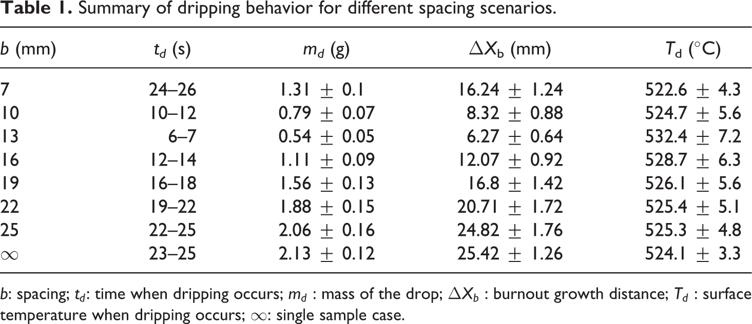
b: spacing; td: time when dripping occurs; md : mass of the drop; ΔXb : burnout growth distance; Td : surface temperature when dripping occurs; ∞: single sample case.
This article does not consider the case of spacing less than 7 mm, as burning PMMA sheet may become soft and cling to the insulated fire board during the experiments. This is disadvantageous for the development of vertical wall burning and dripping behavior. Because oxygen can be supplied for the burning sheet from only one side instead of two sides once the thermoplastic sheet clings closely to the fire board.
Spacing effects
As shown in Table 1, the spacing between the wall and thin PMMA affects the dripping time and mass significantly. Some studies investigated the spacing effect of the upward flame spread between two vertical parallel materials. 10,24 –26 Tamanini and Moussa 10 studied the turbulent burning of vertical parallel walls and reported that the space between two walls is an important parameter, affecting the fire behavior of the two burning walls. If the spacing between the two walls is sufficiently far apart, then the interaction is minimal and the rate of burning becomes the same as that of the single wall case. Wang and Joulain 24,25 conducted a theoretical study to investigate the fire structure, heat transfer, and pyrolysis rate between the vertical parallel burning surfaces with a fire-induced flow. The results indicate that with the decrease in the wall spacing/sample height ratio, the convection and radiation fluxes decreased. Tsai 26 used three configurations (on a flat surface, in a corner, and between parallel surfaces) to confirm that a vertical parallel wall fire can lead to a more rapid fire growth. However, all the studies 10,24 –26 involved only an upward flame spread between two vertical parallel materials. They did not consider the effects of spacing on dripping behavior.
A side-view camera was used to observe the arrival of the flame at the set markers to determine the front and back flame heights simultaneously, as shown in Figure 5. Rangwala et al. 11 applied the thresholds of video images to determine the extent of flame. Audouin et al. 27 determined the flame heights by importing videos into a Matlab program written to analyze the flame heights. After the ignition, a flame was generated that spread upward.
Figure 8 shows the difference between the front and back flame heights (Xff−Xfb). In the 7 mm spacing scenario, the back flame was observed slightly beyond the pyrolysis area (Xp − Xb) and the flame size was smaller. This is probably because of a decrease in the oxygen available between the wall and fuel during the combustion. In the 13 mm spacing scenario, the front flame height was slightly higher than the back flame height and the flame height difference (Xff − Xfb) decreased. As the spacing was increased to 19 mm, the back flame height slightly increased than the front flame height. Because the flow of oxygen available for combustion in the gap increased and stack effect. In the 25 mm spacing case, the interaction was minimal, and the difference in the front and back flame heights became the same as that of the single sample case.
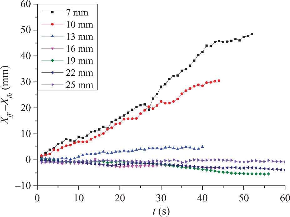
Subtraction of the front flame height from the back flame height.
As the spacing increased, the back flame size increased. Moreover, the back heat losses of flame radiation and convection increased (the back net heat flux to the surface per unit surface area of the material varied). These results can be represented by the following energy balance:

where


where
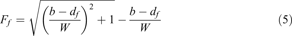
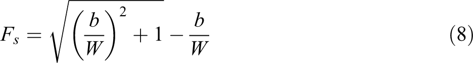
where b is the spacing and df is the flame thickness. The contribution by the front and back heat losses can be described as follows:


where
These equations should be regarded as a study on the effect of heat losses due to flame radiation and convection, because another factor, the change in wall spacings associated with varying net heat flux to the surface, has been removed.
The principal parameters controlling the melt-flow rheology are shear and extensional viscosities. The small-sized dripping would primarily depend on the shear viscosity η or melt flow index of the polymer, whereas the large-sized dripping would be dominated by the melt strength or extensional viscosity ηe . 2 For the uniaxial extension of Newtonian fluid, the extensional viscosity is three times the shear viscosity. For the non-Newtonian fluid of polymer melts, the extensional viscosity is much higher than the shear viscosity. Especially at high shear rate, the extensional viscosity is even two magnitudes higher than the shear viscosity. 29 Thus, it is reasonable that the extensional viscosity can support greater drop mass than the shear viscosity. The dripping of PMMA has been defined as large-sized dripping, 2 and a large-sized dripping may be caused by the temperature increase (i.e. the net heat flux to the surface) of the specimen, extensional viscosity, and stress on the vertical direction resulting from the gravitational force of the melting PMMA. The relationship between the net heat flux and temperature rise rate can be expressed as follows 12 :
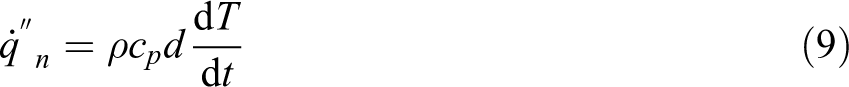
where ρ is the density and cp is the specific heat. The dependence of viscosity on temperature can be expressed by the Arrhenius equation 29 :

where A is a constant for a given polymer,

where B is a constant,
Because of the lack of a complete theory of the effects of spacing on dripping behavior of thermally thin materials and the current transient transfer models 30,31 for flame spread and burning rates of thermoplastics do not consider the dripping and melting behavior, we assumed that the effects of spacing between the wall and PMMA on the dripping behavior of vertical burning thin PMMA were controlled by the net flame heat flux to the surface, extensional viscosity, and gravitational force of dripping mass. At a low wall spacing (7 mm case), the size of back flame was small, as well as the back net heat flux to the surface (consisting of flame heat flux and heat losses due to flame radiation and convection). As spacing increased, the net heat flux to the surface increased, thus increasing the temperature rise rate. This decreased the extensional viscosity and the degradation time of bearing capacity. Thus, the value of dripping time and mass and burnout growth distance decreased as the spacing increased from 7 mm to 13 mm. As spacing increased to 13 mm, the net heat flux to the surface reached the critical value as well as the value of dripping time and mass and burnout growth distance. As spacing increased from 13 mm to 25 mm, the net heat flux to surface decreased (the flame heat flux reached the maximum value, but the back heat losses of flame radiation and convection increased as the spacing increased). Then, the temperature rise rate decreased, leading to the increase in extensional viscosity and degradation time of bearing capacity. Thus, the value of dripping time and mass and burnout growth distance increased as the spacing increased as shown in Table 1. If the wall is sufficiently far apart (spacing more than 25 mm), the interaction is minimal and the net heat flux became the same as the single sample case.
Dripping effects
Because most thermoplastic materials melted and dropped significantly under fire conditions, this behavior inevitably affected the pyrolysis spread rate, particularly in the upward direction. 6 The pyrolysis spread rate Vp was defined as the rate of increase in the pyrolysis height, which was determined using an infrared video recording that traced the pyrolysis (360°C) isotherms. The pyrolysis front Xp was identified by the locus on the solid surface where the temperature reached a characteristic value at which a significant pyrolysis occurred, referred to as the pyrolysis temperature (Tig, pyrolysis temperature was 360°C, obtained by the ignition test). The burnout length Xb was defined as the distance from the bottom of samples to the bottom edge of pyrolysis zone (see Figure 1). Gollner 32 and Rangwala et al. 11 measured the pyrolysis temperatures using thermocouples in the holes drilled from the back of the sample and melted onto the surface. Markstein and de Ris 33 and Gollner et al. 14,34 defined the pyrolysis zone as a blackened underside. A new processing method, based on wavelet decomposition, was developed to detect the pyrolysis front location from the video recordings of bubbling surface by Pizzo et al. 13,35
By tracing the pyrolysis isotherms and top edge of burnout zone, 18,36,37 the time evolutions of the pyrolysis front location Xp and burnout length Xb were obtained as shown in Figure 9. For different spacings of wall and samples, the Xb curves of each figure showed a drastic increase when dripping occurred but slightly affected the Xp trajectory.
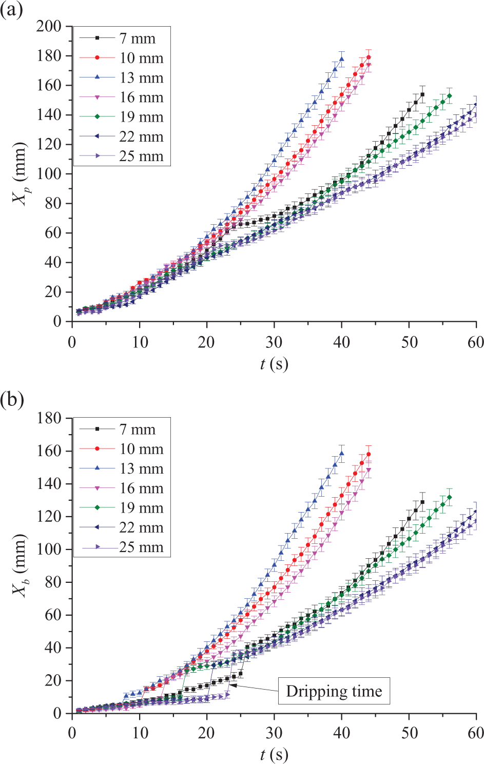
(a) Pyrolysis front trajectory and (b) burnout length. The location of pyrolysis was observed by the infrared camera tracing of 360°C isotherms, and the burnout was traced at the edge of the bottom isotherm.
Figure 10 shows the pyrolysis region length Lp (Lp = Xp − Xb). The value of pyrolysis region Lp always first increased and decreased at the dripping moment and then asymptotically attained a constant value with the increase in time, resulting from the interactions of upward flame spread and dripping behavior.
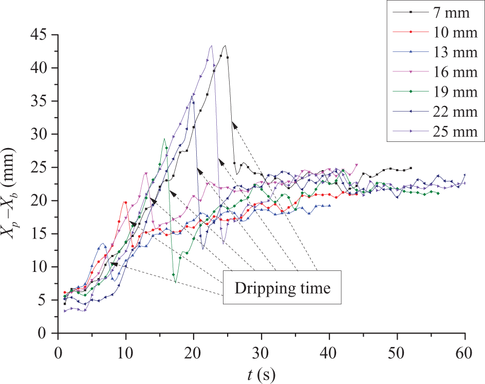
Pyrolysis region for different spacing scenarios.
After the dripping behavior occurred, for all the spacing cases, the pyrolysis length Lp reached an asymptotic steady state when the length of PMMA was infinite, and the same result was obtained for the pyrolysis spread rate. This assumption was confirmed by Markstein and de Ris. 33 They conducted a large-scale experiment on two-dimensional upward flame spread over thin textiles. The pyrolysis spread rate increased with time according to a power-law relationship between the pyrolysis spread rate Vp and pyrolysis length Lp 33 as follows:

where C is a constant and n = 0.5. This power law indicates that the pyrolysis spread rate should ultimately reach an asymptotic steady state.
The expressions for Xp and Xb can be derived from kinematic argument by assuming that the front velocity slowly varies with time. Quintiere 38 introduced an expression for the velocity of pyrolysis front as follows:

where Δt is the characteristic time required for the pyrolysis front to move across the length. We obtained a relationship between Xp and Xb as follows:

The value of Lp reached a constant value after the dripping behavior as shown in Figure 10. Therefore, the pyrolysis spread rate Vp is equal to the burnout spread rate Vb derived from the following terms:

During the tests, the following observations were made: The pyrolysis and burnout spread rates became asymptotically equal. After the dripping, the linear fitting of the data of Xp and Xb was performed. The pyrolysis spread rate Vp and burnout spread rate Vb, the derivatives of the Xp and Xb, were constants as shown in Figure 11, and all the R2 values were higher than 0.99.
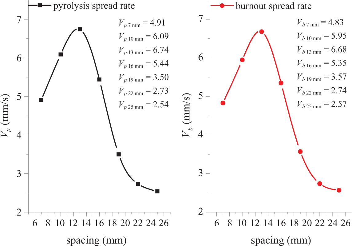
Pyrolysis and burnout spread rate for all the spacings.
Figure 11 shows that the pyrolysis and burnout spread rate first increased with the increase in wall spacing and then decreased monotonously once the ratio exceeded the maximum value. The curves of pyrolysis and burnout spread rate for all the spacings were basically consistent.
According to the hypothesis provided in this study, the effects of dripping behavior on the burning of thermally thin PMMA materials indicate that the modeling of flame spread rate should consider both the melting and dripping behavior, particularly under the vertical orientation upward flame spread conditions. The pyrolysis region reached a constant value after the dripping, resulting from the equal rate of pyrolysis and burnout. We predicted that the pyrolysis and burnout spread rates will be equal in the field of upward flame spread studies of thin materials. The same results were confirmed by Johnston et al. 39
Conclusion
The experimental results obtained in this study provide a hypothesis for the dripping behavior of vertical burning PMMA materials with different spacings to the wall using pure PMMA samples with 200 mm height, 50 mm width, and 2 mm thickness. Different dripping behaviors were observed depending on the spacings of 7, 10, 13, 16, 19, 22, and 25 mm, and the spacing effects were analyzed.
The dripping process was observed using an infrared camera. As the spacing increased, the dripping time and mass and burnout growth distance first decreased and then increased. The predicted critical value occurred at a spacing of 13 mm. No effect was observed when the spacing exceeded 25 mm. The large-sized dripping behavior was assumed to correspond to the net heat flux to the surface, extensional viscosity, and gravitational force of melting PMMA. At an infinite length of PMMA, the pyrolysis zone reaches an asymptotic steady state after the dripping occurs, and the pyrolysis and burnout spread rates will be asymptotically equal.
This work was intended for an in-depth analysis and a better understanding of the mechanism of the effects of spacing between the wall and thin PMMA material on the dripping behavior under vertical burning conditions. It can be qualitatively concluded that the model which based on the net heat flux to the surface provides important parameters, but further studies are necessary to obtain the input data suitable for quantitative predictions.
Footnotes
Declaration of Conflicting Interests
The author(s) declared no potential conflicts of interest with respect to the research, authorship, and/or publication of this article.
Funding
The author(s) disclosed receipt of the following financial support for the research, authorship, and/or publication of this article: The research presented in this article was supported by National Key Research and Development Program of China (nos 2016YFC0800603, 2016YFC0800604, and 2016YFC0800605), China Postdoctoral Science Foundation (no. 2016M590515), Natural Science Foundation of Jiangsu Province (no. SBK2016041452), and National Natural Science Foundation of China (no. 51606215).