
Abstract
Friction stir welding is a recently developed technique for joining low-melting metals and polymers. In the present work, friction stir welded joints of high-density polyethylene (HDPE) sheets were produced using a newly designed tool with a concave shoulder and a grooved conical pin. The joints were produced with and without the additions of ceramic particulates including silicon carbide (SiC), alumina, graphite, and silica. The effect of strain rate on the tensile properties of base material and plain welded joints was examined. In addition to tensile properties of composite joints, hardness profiles across the weld nugget were analyzed. It was observed that the increasing strain rate improved both the tensile strength and the ductility of the plain welded joints. The tool was able to yield a joint efficiency of around 84% in the plain welded samples. Although, in terms of joint efficiency, the composite joints were less efficient than the plain welded HDPE, SiC additions were found to yield better material properties relative to other reinforcements. Finally, it was concluded that an SiC–HDPE composite joint can be of practical importance in high strain rate applications, provided the optimum tool design and stir welding parameters are available.
Keywords
Introduction
Polymeric composites are rapidly replacing metallic materials in engineering applications due to their low densities and growing applicability. 1,2 Given their high strength to weight ratio and high chemical resistance, polymers are the focus of recent developments for automotive and aerospace applications. 3 The thermosetting polymers have the added advantage of high degree of formability. However, large and complex structures cannot be designed, cost effectively, without joining methods. Hence, with the increasing applicability of polymers, there is an increase in the demand of a defect-free joining method for plastics in order to construct large structures. 1 –3 Welding offers some additional advantages over the other joining methods. For example, it reduces the weight by 10% and the cost by 30% relative to mechanical fastening such as riveting. Many other advantages of welding over adhesive bonding and fastening are reported by Amancio-Filho and dos Santos. 1
In general, most of the welding methods require the formation of a molten pool, which accompanies an externally applied pressure, followed by cooling with external pressure maintained. 4 Friction stir welding (FSW) makes use of a nonconsumable tool that rotates at a very high speed while plunged into the surfaces to be joined. The friction between the tool and the surface produces necessary heat and a localized melt pool is generated around the rotating pin of the tool which upon solidification forms the weld joint. 2 Compared to other welding techniques, FSW is an advanced method of joining that can be used for manufacturing large structures with minimum welding defects. Localized heating around the pin of the tool enables lower welding temperature and, hence, results in lower residual stresses and smaller welding distortions. Initially, FSW was developed for aluminum alloys while its use for other metals such as copper, steel, and titanium is growing at a slower pace. 5 Owing to their constantly increasing acceptability, a special attention has been given by the researchers toward the development of the efficient welding methods for the polymers. Given their cost effectiveness, eco-friendliness, and many other advantages, FSW and friction stir processing (FSP) of polymeric materials are currently being investigated to be utilized at mass scale commercially. 6
In the recent years, many articles related to the joining of polymers by FSW have been published addressing the optimization of different welding parameters such as tool geometry, preheat temperature, and rotation and traverse speed of the tool. An overview of the related literature survey is provided in the following.
Simões and Rodrigues 7 focused on the flow of material and its thermomechanical conditions during FSW of a transparent polymer namely polymethyl methacrylate using two different stationary shoulder tools. Pirizadeh et al. 8 used a new tool with double shoulder to produce friction stir welds on acrylonitrile–butadiene–styrene sheets and proposed suitable welding parameters. Panneerselvam and Lenin 9 used left- and right-hand threaded pin conventional tools for FSW of nylon-6 sheets and analyzed the effect of direction of tool rotation on tensile, hardness, and impact properties. Arici and Sinmaz 4 examined the effect of double pass and tool tilt on the tensile and flexural strengths of high-density polyethylene (HDPE) with varying rotational and axial speeds. Rezgui et al.10,11 have thoroughly examined the effects of different FSW parameters on mechanical properties of HDPE using Taguchi method. Azarsa and Mostafapour 2 estimated the FSW parameters for obtaining maximum flexural strength of HDPE sheets using response surface method.
A more extensive research on FSW of HDPE was carried out by Vijendra and Sharma. 10 They used i-FSW, which means that the tool was heated through induction coil and the temperature was controlled through infrared sensors during welding. Şerban et al. 11 have determined the influence of temperature and strain rate on the tensile properties of polyamide 12-based semicrystalline polymer. Farrokh and Khan 12 investigated the effect of strain rate upon the yield behavior of Nylon-101. They established a precise definition of yield and identified several points on the yield loci by conducting tests in different loading orientations and strain rates. Unlike metals, the increase in ductility in polymers with increasing strain rate is attributed to the stress relaxation due to viscoelasticity and toughening due to crazing. 13 FSP has recently shown potential for properties enhancement of surfaces by making surface composites. For example, the improvement in hardness, abrasion resistance, and corrosion resistance of aluminum and copper have been reported by various authors. 14 –17 Improvement in the hardness of polymer-based surface composites has been reported by Barmouz et al. 18 who used HDPE as matrix and nanoclay as reinforcement.
In the present work, a new tool with simple design has been developed to produce FSW plain welded and composite joints of HDPE. The effect of strain rate on the tensile response of the plain welded samples is reported and tensile behavior of both plain and composite joints is identified. Variation of hardness across the weld nugget has been investigated and related to the joint efficiency.
Experimental work
Materials and tool geometry
Two types of friction stir welds, namely, plain and composite weld joints, were produced on 6 mm thick sheets of commercial HDPE using a vertical milling machine. The composite welds were produced by reinforcing with particulate ceramics including SiC, silica, alumina, and graphite, while the plain welds were produced without any reinforcement. These joints will, henceforth, be referred to as SiC-HDPE, silica-HDPE, alumina-HDPE, graphite-HDPE, and plain-HDPE, respectively. The micrographs of the particulate ceramics are shown in Figure 1 and their average particle size is listed in Table 1.
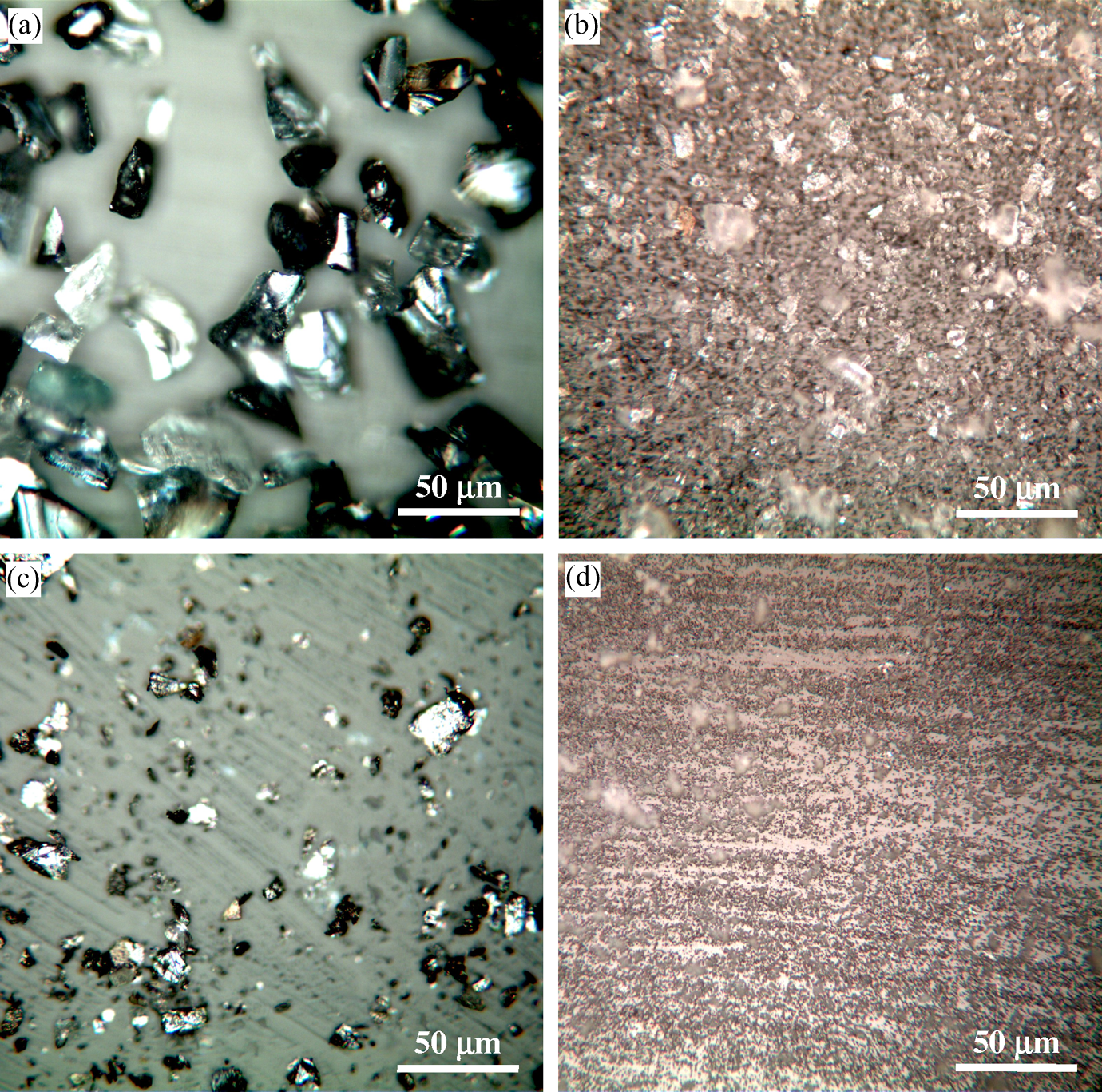
Micrographs of particulate ceramics: (a) SiC, (b) silica, (c) graphite, and (d) alumina.
Particle sizes of the reinforcements.
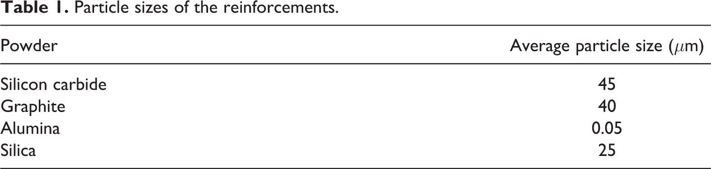
The FSW tool was machined out of commercially available stainless steel, where the design was optimized from a simple geometry as shown in Figure 2. The first and the simplest tool had neither the concavity in the shoulder nor the grooves on the conical pin, called straight-shoulder smooth-pin (SSSP) tool (see Figure 2(a)). When welding was performed with this tool, it was observed that the polymer, due to increasing temperature, tended to stick to the smooth surface of the pin, thereby decreasing the material stirring action around the pin. Additionally, the shoulder, instead of directing the material back into the cut produced behind the tool pin, allowed the softened polymer to eject in the radial direction during the friction stirring, leading to a defective weld joint. In order to contain the material right above the weld joint and push it back into the cut produced, a concavity in the shoulder was provided as shown in Figure 2(b), a concave-shoulder smooth-pin (CSSP) tool. Although this resolved the problem of material escaping from underneath the tool to some extent, it could not deter polymer sticking on the conical pin. After several attempts, an optimized geometry with two grooves, called concave-shoulder grooved-pin (CSGP) tool as shown in Figure 2(c) and (d), was found to improve friction at the tool/material interface and resulted in a minimum pileup and sticking of the polymer upon the tool pin. The final tool geometry is a new design, which can provide optimum friction stirring of polymeric material during FSW. The defective weld joints produced using different tools will be discussed briefly in “Results and discussion” section.
Tool geometry: (a) straight-shoulder smooth-pin (SSSP), (b) concave-shoulder smooth-pin (CSSP), (c) concave-shoulder grooved-pin (CSGP), and (d) actual tool (all dimensions are in millimeters).
Welding setup and parameters
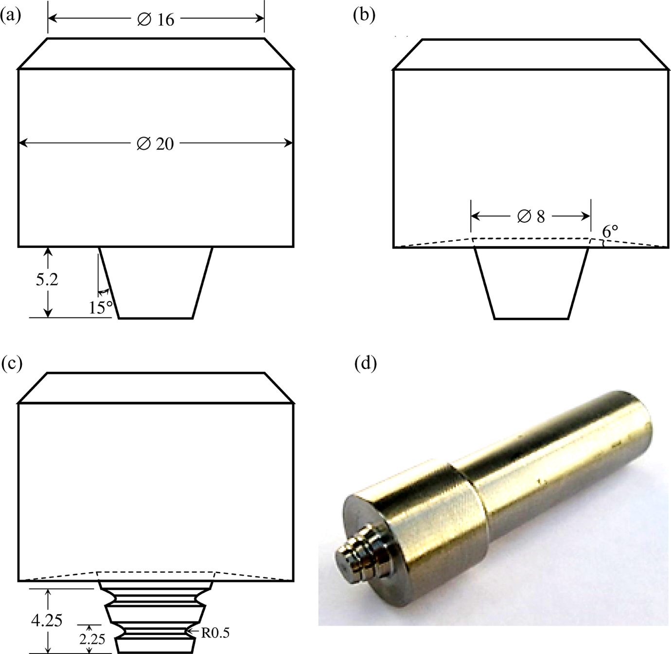
FSW setup and geometry of the welded specimen are shown in Figure 3. Butt joints were produced using HDPE sheets of size 350 mm × 75 mm and thickness 6 mm. The sheets, along with a wooden backing plate, were clamped rigidly on the milling bed with the help of mild steel clamps such that the joint line was parallel to the longitudinal direction of the milling bed. A range of optimized FSW parameters for HDPE have already been reported by some researchers. 2,19,20 Keeping in view the published data for the optimized parameters and operating range of the vertical milling machine, some welds were produced at different rotational and traverse speeds of the tool. A related description about parameter selection is provided in “Results and discussion” section. Based on the physical appearance of the samples, a rotational speed of 1660 r/min and a linear axial/traverse speed of 24 mm/min were selected as optimum stir welding parameters with the designed tool. All the samples for which the mechanical properties are presented in this work were welded at these optimum parameters.
(a) Schematics of the experimental setup, (b) actual setup, (c) geometry of the welded specimen, and (d) FSW in process. FSW: friction stir welding.
For the composite welds, the faying surfaces of the sheets were machined using a drill bit of 2 mm diameter to make slots of 12 mm × 3 mm cross section (i.e. 2 mm wide, 3 mm deep, and 12 mm long). Each two slots were separated by a distance of 25 mm along the joint. The sheets were clamped on the milling bed and then these slots were filled with reinforcing powders and sealed by applying candle wax. In each experiment of FSW, prior to applying the axial movement of the tool, a dwell time of 20 s was given in order to achieve the temperature required to fuse the polymer under pressure behind the tool pin. After welding, the sheets were allowed to cool down to the room temperature for almost 10 min before their removal from the fixture.
Weld joints: Test procedures
ASTM D638—The Standard Test Method for Tensile Properties of Plastics 21 was followed to determine the tensile properties of FSW joints. Prior to cutting the samples for tensile tests, the joint was face milled from both root and crown sides using a 25 mm diameter face mill cutter. The objective of face milling was to obtain pure stir zone within the test specimen and to remove welding defects such as surface cracks, porosity, and so on. The tensile test specimens were extracted using an end mill cutter of 2 mm such that the axis of the sample was perpendicular to the joint line (see Figure 4). Tensile testing was carried out on an Instron 8501 series 100 kN universal testing machine (TecQuipment Ltd., Nottingham, UK). The machine was operated in a displacement controlled regime, that is, the relative movement of the clamping jaws was monitored. Since the plain welded and composite joints were located well within the gauge length (25 mm) of the tensile test specimens, the strain rate was calculated as a ratio of the displacement rate to the gauge length. Base material and plain welded samples were tested at the displacement rates of 0.50, 1.63, 3.88, and 5.00 mm/min, corresponding to the strain rates of 3.3 × 10⁻⁴, 1.1 × 10⁻³, 2.6 × 10⁻³, and 3.3 × 10⁻³/s, respectively. For each test, the modulus of elasticity (E), tensile strength at yield (σu ), and strains at yield (εu ) and fracture (εf ) were measured where the definitions of the parameters are in accordance with the ASTM D638. 21
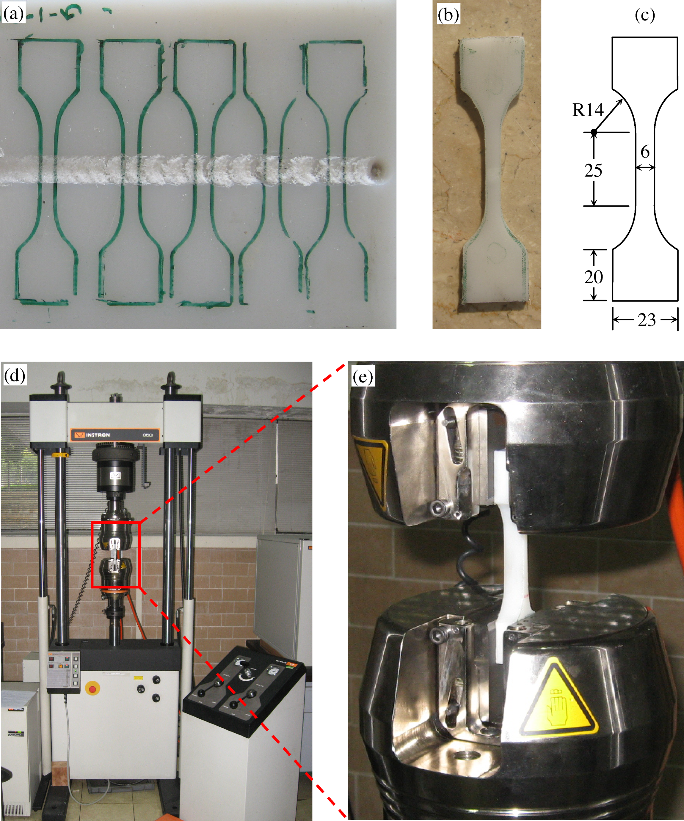
Tensile testing: (a) samples demarcation on HDPE welded plate, (b) extracted sample, (c) geometry of the sample (dimensions in millimeters), (d) Instron 8501 universal testing machine, and (e) enlarged view of mounted sample. HDPE: high-density polyethylene.
Hardness profiles were taken on the cross-sectional surface of the plain and composite welded samples using a Vickers hardness (HV) testing machine with a pyramid-shaped microindenter. The cross sections of the welded samples were ground and polished to a finish of approximately 5 µm. The indents were impinged with a gap of 1 mm, across a length of 12 mm from weld nugget (stir center) on both the advancing and retreating sides. For each hardness measurement, the indents were made under a load of 50 g with a dwell time of 15 s.
Scanning electron microscope (SEM) images were obtained from the fractured surfaces of the plain welded as well as composite joints. Differential scanning calorimetry (DSC) of the base material and the stir zone was performed in order to calculate the percent crystallinity of the samples, which is equal to the ratio of the enthalpy of fusion in partially crystalline state (
Results and discussion
Tool design and FSW parameters optimization
In any welding process, it is always desirable that the welding parameters be adjusted beforehand to achieve a sound weld bead. These parameters are highly dependent upon the material being welded and the ambient conditions. In FSW, the tool design has a direct influence upon the appearance and quality of the weld joint. For this reason, a change in tool design necessitates the determination of a suitable combination of rotational and translational speeds. 2 Recently, Azarsa and Mostafapour reported that the rotational and traverse speeds of 1400 r/min and 15 mm/min are the most suitable parameters for FSW of HDPE. However, limited by the operating range of the milling machine used in the present work, a minimum value of 1660 r/min was used as the rotation speed throughout, whereas the traverse speed was set at 15 mm/min to observe the effect of different tool designs.
Figure 5 illustrates the difference among the weld bead appearance resulting due to the SSSP, CSSP, and CSGP tools. As mentioned earlier, the SSSP tool, with no shoulder concavity, does not allow accumulation of material underneath the shoulder and, hence, ejects the softened polymer in the radial direction, thereby, leading to the lack of material within the stir zone. Although the CSSP tool minimizes the material escape, the sticking and thickening of polymer around the smooth pin reduces the effective area of the concave shoulder and, hence, limits the overall efficiency of the tool to keep the polymer within the stir zone (see the enlarged regions (a) and (b) in Figure 5). The CSGP tool, however, maximizes the tool efficiency by improving the friction and stirring action due to increased contact area of the grooved pin with the polymer and by directing the “plasticized” polymer back into the cut produced. Note that the zoomed-in region (c) in Figure 5 corresponding to the weld bead produced by CSGP tool shows minimum ejection of material compared to those produced by SSSP (regions (d) and (e) and CSSP (regions (a) and (b)) tools.
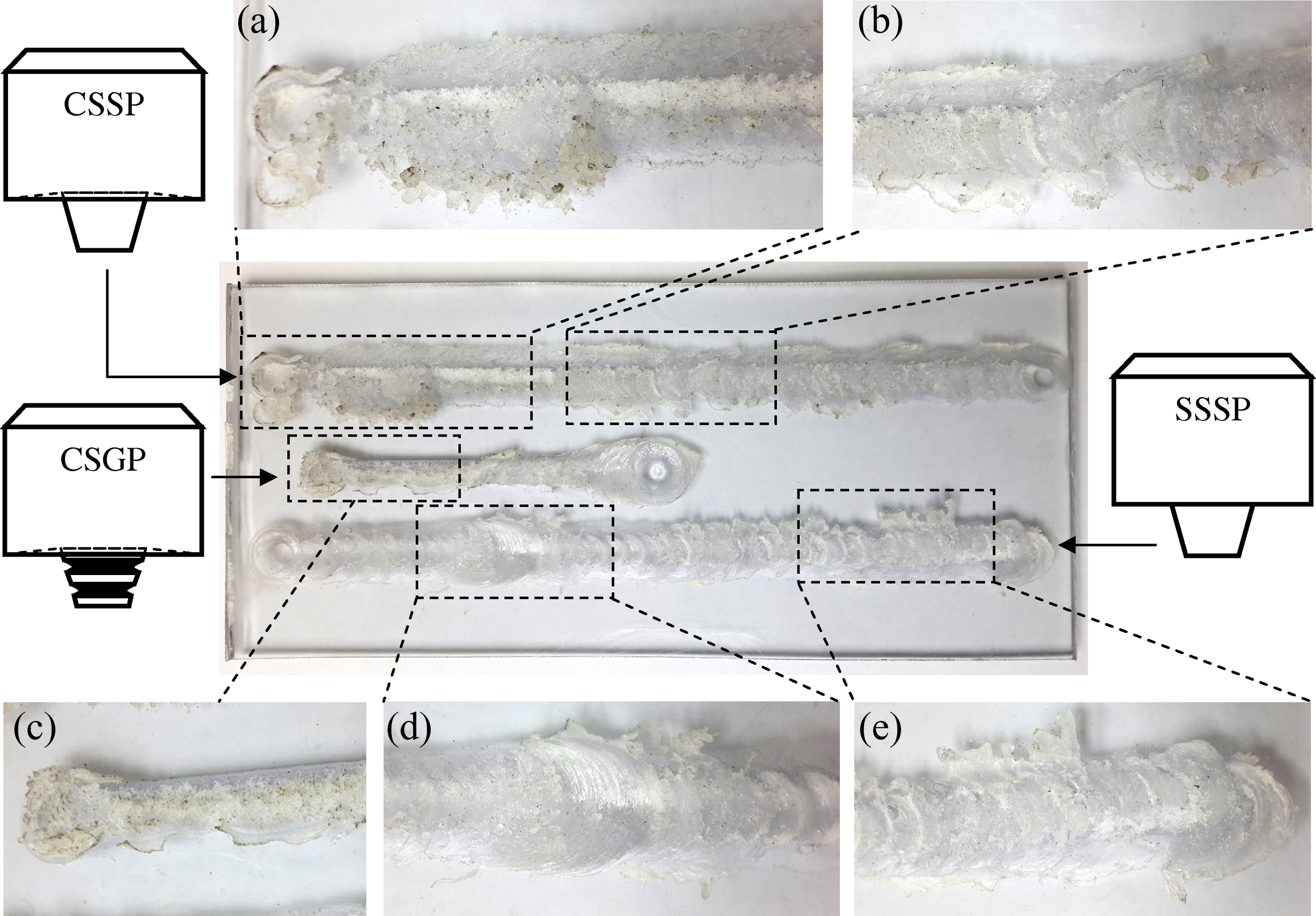
Welding defects resulting due to CSSP tool magnified in (a, b), CSGP tool in (c), and SSSP tool in (d, e). CSSP: concave-shoulder smooth-pin; CSGP: concave-shoulder grooved-pin; SSSP: straight-shoulder smooth-pin.
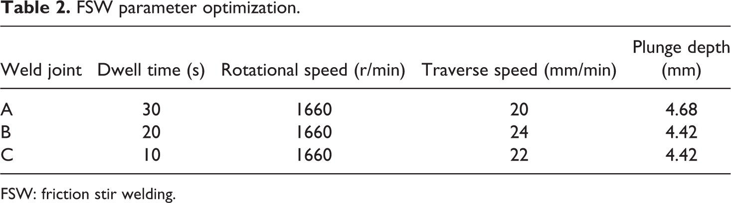
Nevertheless, the tool design (CSGP) has its limitations and, therefore, the parameters such as rotational and traverse speeds must be adjusted to suit the material being welded. Figure 6 illustrates three weld joints made using different parameter sets, A, B, and C summarized in Table 2. Note that the rotational speed is fixed at 1660 r/min throughout. It may be observed that a dwell time of 30 s, joint A, leads to the material ejection since the shoulder concavity is unable to carry excessive amount of polymer. However, no ejection of material was observed when the dwell time was varied from 10 to 20 s (see joints C and B, respectively, in Figure 6). Although the effect of tool penetration depth, called the plunge depth, is small, yet these values are also reported in Table 2. It may be noticed that a plunge depth of 4.42 mm, that is, 85% to that of pin height (5.2 mm), yielded better results in terms of producing excess material as compared to that of 4.68 mm. Finally, the traverse speed was found to be the most important parameter to produce a sound weld. Recall that the translational speed during the tool design stage was set at 15 mm/min, which led to the polymer ejection in all the cases. This means that the travel speed must be increased to avoid the material escape. It may be observed that the speed of 20 mm/min in case of joint A was still too slow to completely eliminate the defect. Although a speed of 22 mm/min in case of joint C minimized the material ejection to a great extent, 24 mm/min in the joint B was found to be the most appropriate in terms of the weld bead appearance.
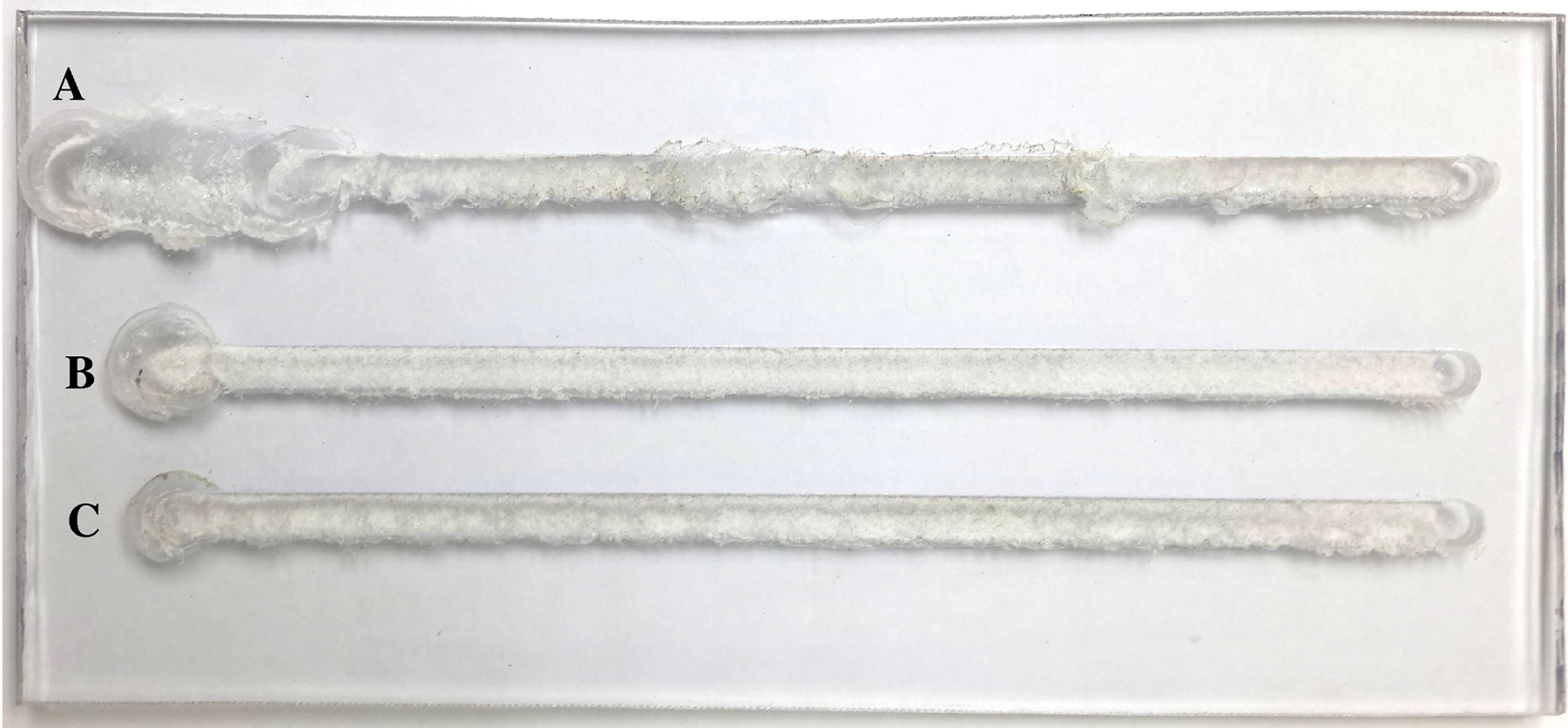
Weld joints made using CSGP tool at the traverse speeds of (A) 20 mm/min, (B) 24 mm/min, and (C) 22 mm/min (additional FSW parameters are defined in Table 2). CSGP: concave-shoulder grooved-pin; FSW: friction stir welding.
FSW parameter optimization.
FSW: friction stir welding.
Tensile testing
Figure 7 shows the stress–strain curves of the base material and plain welded samples. It is obvious that the slopes of the elastic part of the curves and the tensile strength at yield are increasing with the increasing strain rates. Figure 8 illustrates that the elastic modulus (E), tensile strength at yield (σu ), and the strains at yield (εu ) and fracture (εf ) are all increasing as a function of displacement and strain rates. This is a typical behavior of semicrystalline uncross-linked polymers like HDPE and is attributed to the stress relaxation of the molecular chains when loaded. The relaxation of molecular chains makes the deformation process time dependent. A higher rate of deformation reduces the loading time, causing the stress increment to reach higher levels. However, with lower strain rates, enough relaxation time is available for the molecular chains and, hence, a higher stress does not develop within the material. The deformation of polymers constitutes two components, namely, the time-dependent behavior and the time-independent behavior. The time-dependent component of deformation only depends upon the molecular structure of the polymer and stress relaxation with time and, hence, it remains almost constant in all the cases. On the other hand, the time-independent component of deformation responds immediately to the application of load. It depends upon the stress level the material can withstand before the start of stress relaxation of molecular chains. Since the stress increments reach higher levels at a faster deformation rate, the time-independent component dominates the overall deformation behavior. 13
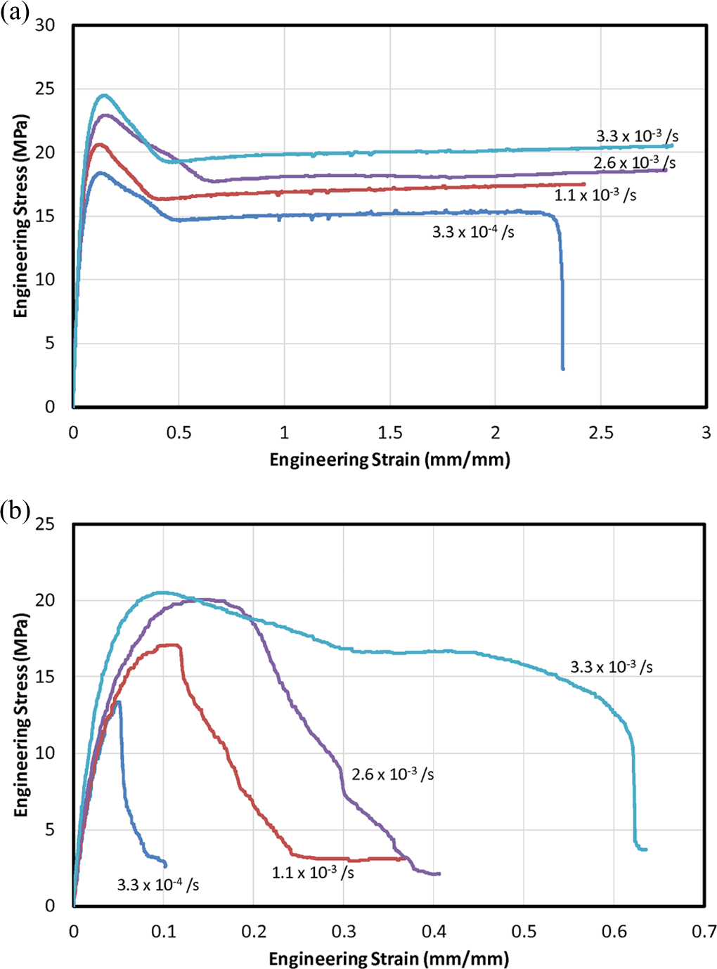
Stress–strain curves of (a) unwelded and (b) welded HDPE at the strain rates of 3.3 × 10⁻⁴, 1.1 × 10⁻³, 2.6 × 10⁻³, and 3.3 × 10⁻³/s corresponding to the displacement rates of 0.50, 1.63, 3.88, and 5.00 mm/min, respectively. HDPE: high-density polyethylene.
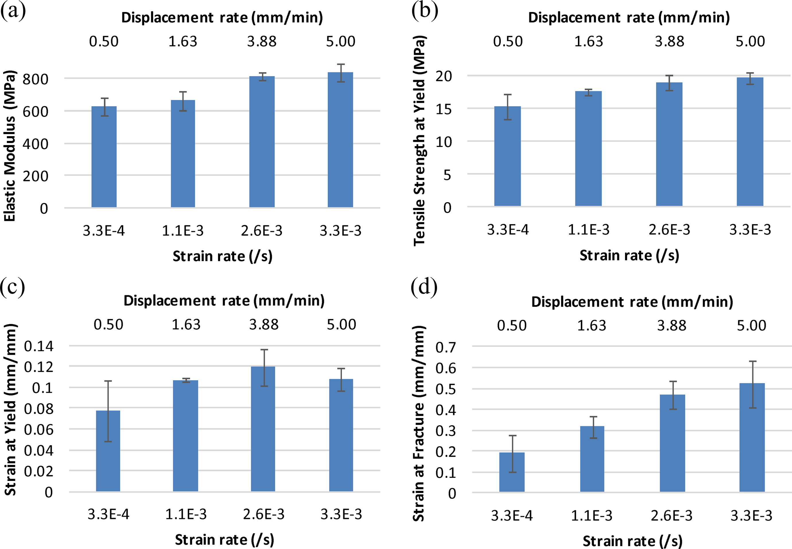
Mechanical properties of plain welded joints at different displacement and strain rates: (a) elastic modulus, (b) tensile strength at yield, (c) total strain at yield, and (d) total strain at fracture.
A comparison of the mechanical properties of the plain welded joints to the base material (Figure 9) indicates that most of the samples behaved in a ductile manner. Moreover, the strength efficiency of the joint, defined as a ratio of the tensile strength at yield of the welded joint to that of the unwelded base material, ranges from 81% to 85%, which in turn, depends greatly upon the tool design and the selection of optimum welding parameters.
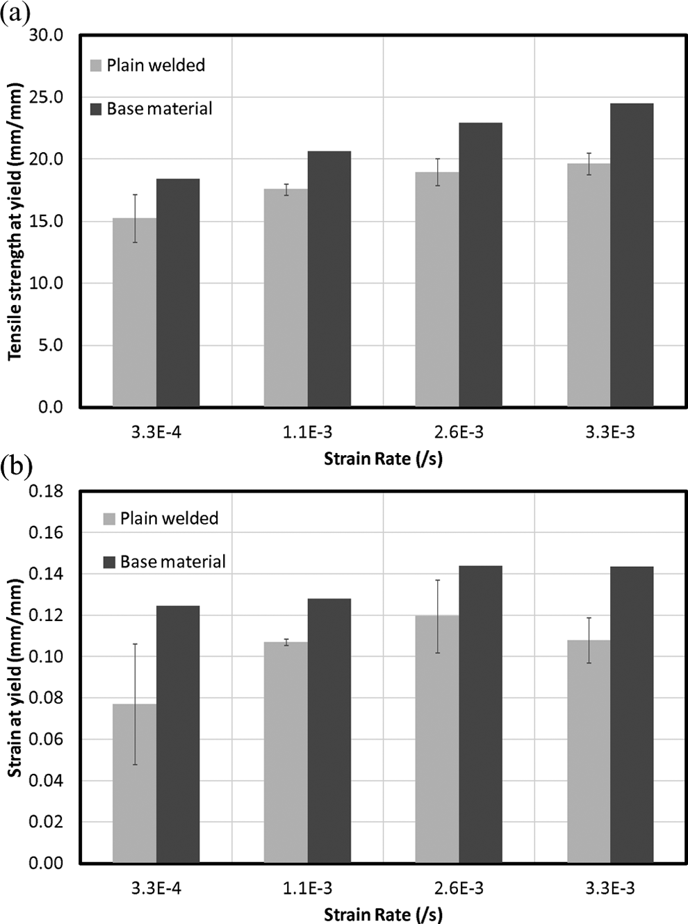
Comparison of base material and plain welded joints at different strain rates: (a) tensile strength at yield and (b) strain at yield.
The composite joints were tested at a strain rate of 3.3 × 10⁻³/s only. The engineering stress–strain curves and the mechanical properties of these joints are shown in Figure 10. It was observed that the joint efficiency decreased for all the composite joints compared to plain welded HDPE samples. In terms of tensile strength at yield, the joint efficiency among the composite samples was found to be the highest for the SiC-reinforced joints, that is, 72.3% compared to 84.0% of plain welded samples, while the lowest joint efficiency of 63.8% was recorded for silica-reinforced joints. The strain at yield remained almost constant throughout. Nevertheless, the strain at fracture showed highly ductile behavior for the plain HDPE, the SiC-HDPE, and the graphite-HDPE joints and mildly ductile behavior for the alumina-HDPE and the silica-HDPE joints.
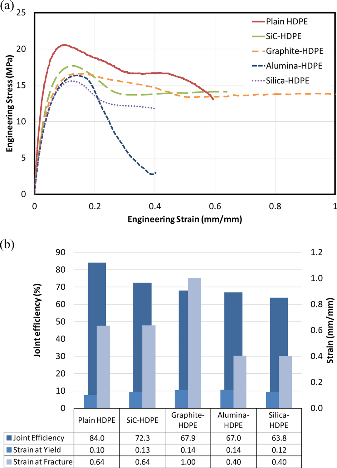
Mechanical response of composite joints compared to plain welded joints: (a) stress–strain curves at the strain rate of 3.3 × 10⁻³/s and (b) comparison of mechanical properties.
Graphite, being a good lubricant relative to other reinforcements used, distributes in the stir zone with a relative ease and does not cause stress raisers within the polymer matrix. Its lubricating nature reduces the friction between the molecular chains of HDPE and, hence, the plastic flow of the material continues without fracture over large deformations demonstrating higher ductility. SiC, alumina, and silica, on the other hand, act as particles with sharp corners and, therefore, provide stress raisers at the microstructure level and reduce the ductility of HDPE joints. 1 Compared to the other samples, the higher joint efficiency of SiC may be attributed to its better ability to couple with HDPE, thereby, making a stronger interface. 22,23 Alumina and silica reinforcements can only improve the tensile strength by having some prior surface treatments 24 –26 ; however, SiC has been reported to improve mechanical properties with and without surface treatments. 22
Hardness testing
The hardness profile across the weld nugget for polymers is opposite to that for metals, that is, in metals, the hardness increases at the weld center, 17 whereas it tends to decrease in polymers. 10 The reason for such a behavior lies in the very nature of the semicrystalline structure of the polymers. Unlike metals, the microstructure of the semicrystalline polymers like HDPE ranges from the partially crystalline (precisely aligned polymer chains) to the partially amorphous (randomly oriented loose chains) regions. During FSW, the stir zone experiences severe plastic deformation and fusion within the weld nugget. The stirring effect leads to the randomization of the crystalline regions, while the fusion and the rapid cooling in air do not allow sufficient time for a complete orientation of the molecular chains. It should, therefore, be expected that the ratio of amorphous to crystalline regions would be higher in the welded structure as compared to the unwelded material. Consequently, the hardness, being proportional to the degree of crystallinity, would be relatively less within the stir zone than the adjacent base material. It should also be mentioned that the joint efficiency is dependent upon the hardness reduction ratio; the more the decrease in hardness at the weld center, the lesser the joint efficiency. 27,10 The concept of making surface composites by FSP can be coupled with FSW of polymers with the objective of further improving the joint efficiency by minimizing the hardness reduction ratio. 28
Figure 11 shows the variation of hardness across the weld nugget in different composite joints. Note that the hardness was measured within the depth of 3 mm from the top surface (Figure 11(a)) to avoid the surface effects due to shoulder sliding. In general, hardness dropped noticeably within the stir zone of plain welded HDPE and graphite- and silica-reinforced composite joints. On the contrary, the hardness across the alumina- and SiC-reinforced weld joints remains almost constant, thereby indicating improvement in the properties of the composite produced. This finding is in accordance with the highly ductile behavior depicted by the plain HDPE, graphite-HDPE, and silica-HDPE weld joints and the mildly ductile response shown by the alumina-HDPE and SiC-HDPE weld joints during tensile testing (see Figure 10). Although an overall trend is consistent, small variations may be attributed to the defects within the weld joints, hardness measure directly over the particulate reinforcement, and so on. It may be noticed from Figure 11(b) that the average hardness value within the stir zone is minimum (HV: 1.83) for silica-HDPE and maximum (HV: 2.79) for SiC-HDPE. It has been mentioned earlier that SiC addition in HDPE yields improved mechanical properties of the composites. 22,23 With respect to the average HV within the stir zone, the values for all the samples can be arranged as HV (SiC-HDPE) > HV (alumina-HDPE) > HV (plain HDPE) > HV (graphite-HDPE) > HV (silica-HDPE).
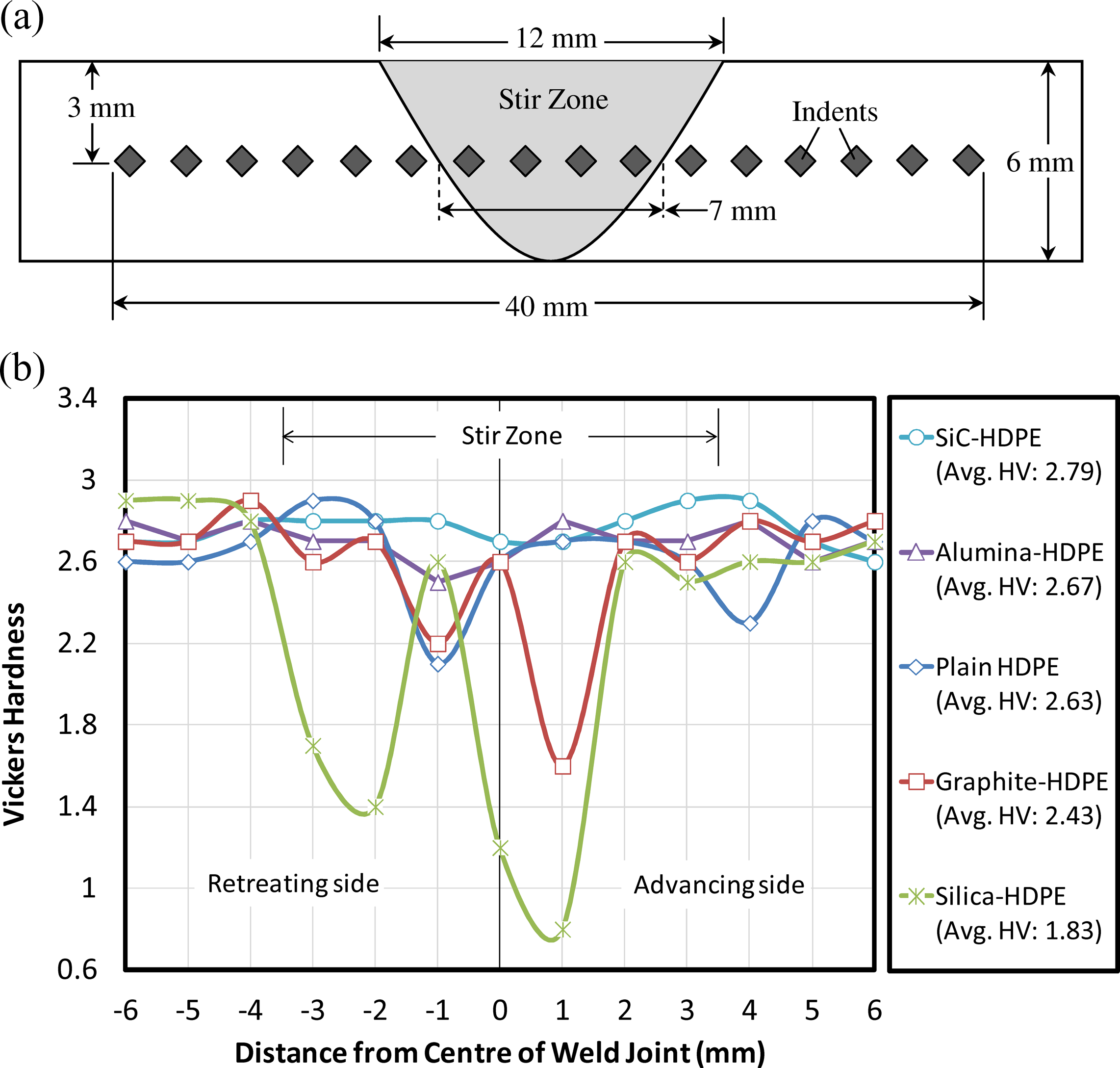
(a) Schematic of weld cross section and indents location and (b) hardness profiles across weld nugget for different composite joints.
SEM and DSC analyses
Figure 12 shows the fracture of typical tensile test specimen from the weld stir zone. Additionally, SEM images obtained from the fractured surfaces of the SiC-HDPE, alumina-HDPE, plain HDPE, graphite-HDPE, and silica-HDPE are also presented for a comparative analysis. Note that all the micrographs illustrate flow pattern of the polymer, indicating predominant ductile behavior during plastic deformation. However, Figure 12(a) and (b), corresponding to SiC-HDPE and alumina-HDPE, respectively, shows regions of decreased plastic flow with slightly brittle behavior. These regions are responsible for improving the hardness within the stir zone. Figure 12(c), (d), and (e), referring to plain HDPE, graphite-HDPE and silica-HDPE, respectively, demonstrates highly ductile behavior with a complete absence of brittle fracture regions. Recall that the plain HDPE sample contains no reinforcement but the welding defects such as porosity, which deteriorate the material properties as compared to unwelded HDPE. Owing to its lubricating nature, the graphite addition, although reduces the hardness, leads to an improved plastic flow and a completely ductile fracture. Nevertheless, the silica reinforcement acts like isolated rigid particles and, hence, gives rise to the stress raisers. It may be noticed from Figure 12(e) that the polymer flows around the silica particles, thereby, leading to an early crack propagation at low stress values.
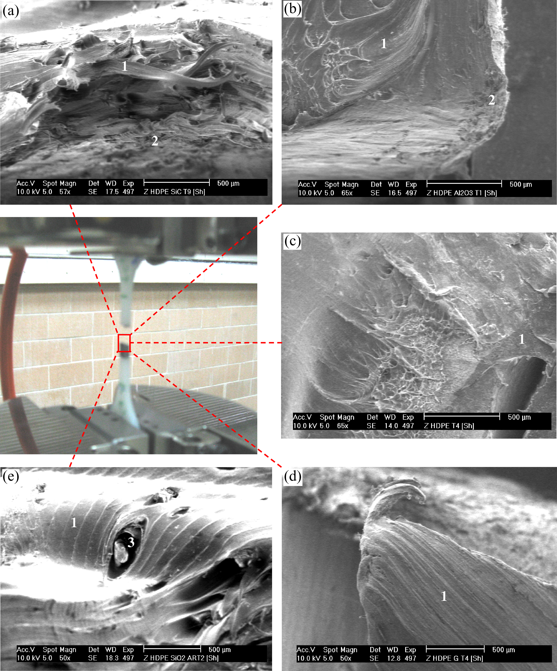
SEM images of the fracture zone: (a) SiC-HDPE, (b) alumina-HDPE, (c) plain-HDPE, (d) graphite-HDPE, and (e) silica-HDPE (1. ductile flow, 2. brittle fracture, 3. isolated rigid inclusion). SEM: scanning electron microscope; HDPE: high-density polyethylene.
Figure 13 presents two DSC curves of the specimens taken from the unaffected HDPE sheet (base material) and the center of stir zone of plain welded joint. Given that the enthalpy of fusion of 100% crystalline HDPE is 287.3 J/g, 29 the percent crystallinity was found to be 24.3% and 17.0% for the base material and stir zone, respectively. Here, the decrease in crystallinity is a direct consequence of stirring as well as rapid cooling of weld zone. As mentioned earlier, the semicrystalline polymers require time to grow their crystals. A higher fraction of amorphous regions deteriorates the overall properties. The observation is consistent with the explanation provided in the previous section.
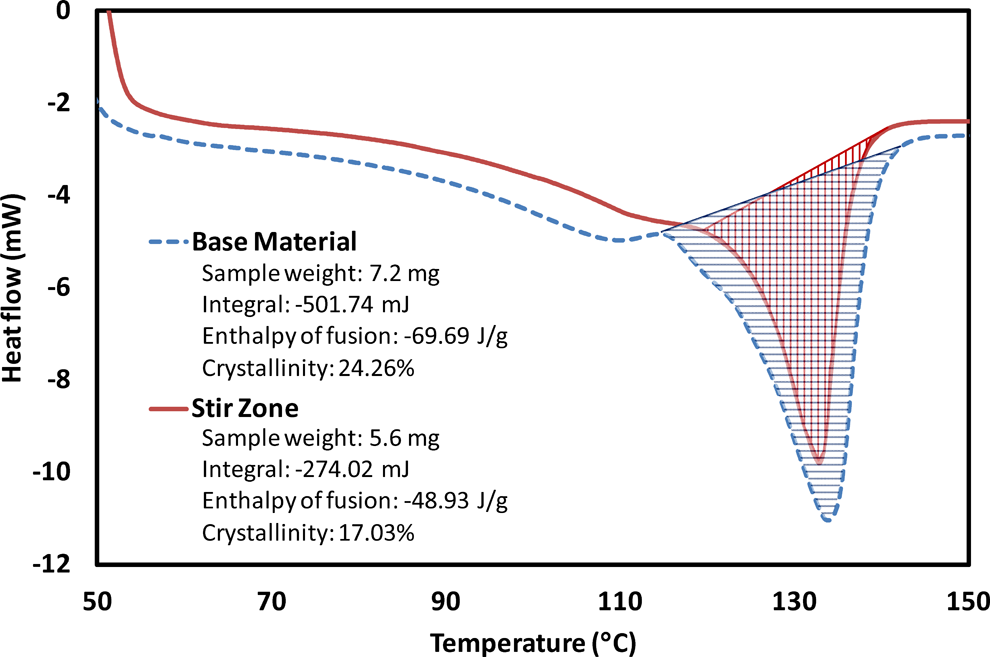
DSC curves of samples taken from base material and stir zone. DSC: differential scanning calorimetry.
Although the study of the effect of ceramic reinforcements upon the crystallinity of the weld zone could be of interest, it is, however, beyond the scope of the present work due to highly inhomogeneous and nonuniform distribution of the ceramic particulates at microscopic level within the weld bead. Nevertheless, irrespective of the composition, the center of weld nugget, being the site of large residual strains and reduced crystallinity, remains a potential location for the fracture to occur. 10
Conclusions
In the present work, a newly designed tool with grooved conical pin geometry was used to produce friction stir welded joints of HDPE. The joints were produced with and without additions of ceramic inclusions. It may be concluded from the above discussion that the weld joint quality is not only dependent upon stir welding parameters but also a function of tool design geometry. The effect of increasing strain rate was such that it led to the increase in the modulus of elasticity, tensile strength at yield, and the ductility of the base material as well as welded samples. It may, therefore, be established that the FSW joints of HDPE can be of practical importance where high strain rates are involved. Although the plain welded samples yielded maximum joint efficiency of around 84%, SiC as reinforcement showed better results compared to other inclusions. It may be expected that variations in particle size, shape morphology, volume fraction, and so on of SiC within the HDPE matrix would improve the mechanical properties of the composite. Moreover, the DSC analysis of the composite joints, keeping in view the inhomogeneous and nonuniform distribution of the second phase particles due to mechanical stirring, requires a fully dedicated investigation. These areas may further be explored in future.
Footnotes
Declaration of Conflicting Interests
The author(s) declared no potential conflicts of interest with respect to the research, authorship, and/or publication of this article.
Funding
The author(s) received no financial support for the research, authorship, and/or publication of this article.