
Abstract
A new manufacturing concept named multilayered hybrid (MLH) roving was invented in the form of a fiber roving separated evenly into several sublayers by thermoplastic films, which is manufactured by the sequential processes of spreading, fixing, and folding. This concept is aimed to combine the variety in processing of commingled roving and the variety in material configuration of organic sheet. For the review on impregnation basics, the Kozeny–Carman equation was examined on the packed bed of fibers, not of particles, to check out the controllable parameter. Also, the newly derived spreading equation was prepared to prevent the current problem of center splitting during fiber spreading processes. The impregnation quality was practically verified by the bending test on the unbalanced (2/1) woven fabric made of polypropylene (PP) and glass fiber (GF) MLH roving, PP/GF45 vol.% (70 wt%), which had been impregnated by the continuous compression molding machine considering the conditions of mass production. The representative flexural properties were statistically determined with the characteristic behavior of stress–strain curve. The coefficient-of-variation values were in the moderate range of around 5%, except for the strength and strain in minor direction that can be explained by the waving of fibers due to the lack of applied tension during and before impregnation.
Introduction
Continuous fiber–reinforced thermoplastic materials
Manufacturing of continuous fiber–reinforced thermoplastic materials often starts out as the form of intermediate products, which can be classified into several approaches such as pre-impregnated tow, film stacking, commingled roving, powder impregnated fiber bundle, and so on. 1 All attempts are mainly focusing on how to overcome the disadvantages of high viscous thermoplastic matrix and how to achieve the fast and reliable impregnation of fiber reinforcements. There have been well-known products of pre-impregnated tows, the so-called tapes (e.g. Suprem™ (Switzerland) and Celstran® (USA)), and of fully impregnated plates, the so-called organic sheets (e.g. TEPEX®), based on film stacking between woven fabrics. The fiber content of organic sheets is typically in the range of 45–50 vol.%, in which several plies of woven fabric (glass fiber of 1200 TEX or carbon fiber of 3 k) are impregnated with a thermoplastic matrix, for example, polypropylene (PP), polyamide 6 (PA6), polyamide 66 (PA66), thermoplastic polyurethane (TPU) or polyphenylene sulfide (PPS)). Thus, organic sheets have the variety in material configuration, but it is limited to only consolidated plates and has many crossing points of warp and weft rovings where the impregnation is difficult and time-consuming process.
Besides the impregnated semifinished products, un-impregnated materials based on commingled roving (e.g. TwinTEX® (USA)) are also available. The main grade of TwinTEX® is PP/GF35 that is a commingling of PP fiber and glass fiber of 35 vol.% (60 wt%), having the linear density of 1870 TEX (g km−1). 2,3 The commingled roving is suitable for various processing, for example, filament winding, pultrusion, and woven or non-crimp fabrics, 4 whereas it has the risk of reduced mechanical properties due to irregularly distributed and movable fibers in a commingled roving.
Scope and objective
This article introduces a new manufacturing concept of continuous fiber–reinforced thermoplastic materials, named multilayered hybrid (MLH) roving, which is aimed to combine the variety in processing of commingled roving and the variety in material configuration of organic sheet. To bring out the concept of MLH roving, the impregnation basics like Kozeny–Carman equation and the processing basics like spreading equation were fundamentally reviewed. The unbalanced (2/1) woven fabric made of PP/GF45 vol.% (70 wt%) MLH roving was impregnated and consolidated by the continuous compression molding (CCM) machine, considering the conditions of mass production. Those impregnation quality and representative properties were determined by the bending test with the analysis of characteristic behavior of stress–strain curve.
Review on impregnation
Derivation of general Kozeny–Carman equation
The Kozeny–Carman equation can be derived by the capillary model schematized in Figure 1. Here, the Hagen–Poiseuille equation describes the pressure drop (ΔP) of an incompressible and Newtonian fluid in steady laminar flow through a very long cylindrical pipe of constant cross section, assuming there are no “end effects.” 5,6 To take the macroscopic view on the flow, the mean velocity (νc ) in a cylindrical pipe should be expressed in terms of the superficial velocity (ν), with the porosity (ε) and the tortuous degree. The tortuous degree is the ratio of the actual path length (hc ) to the height (Δh ) of packed bed.
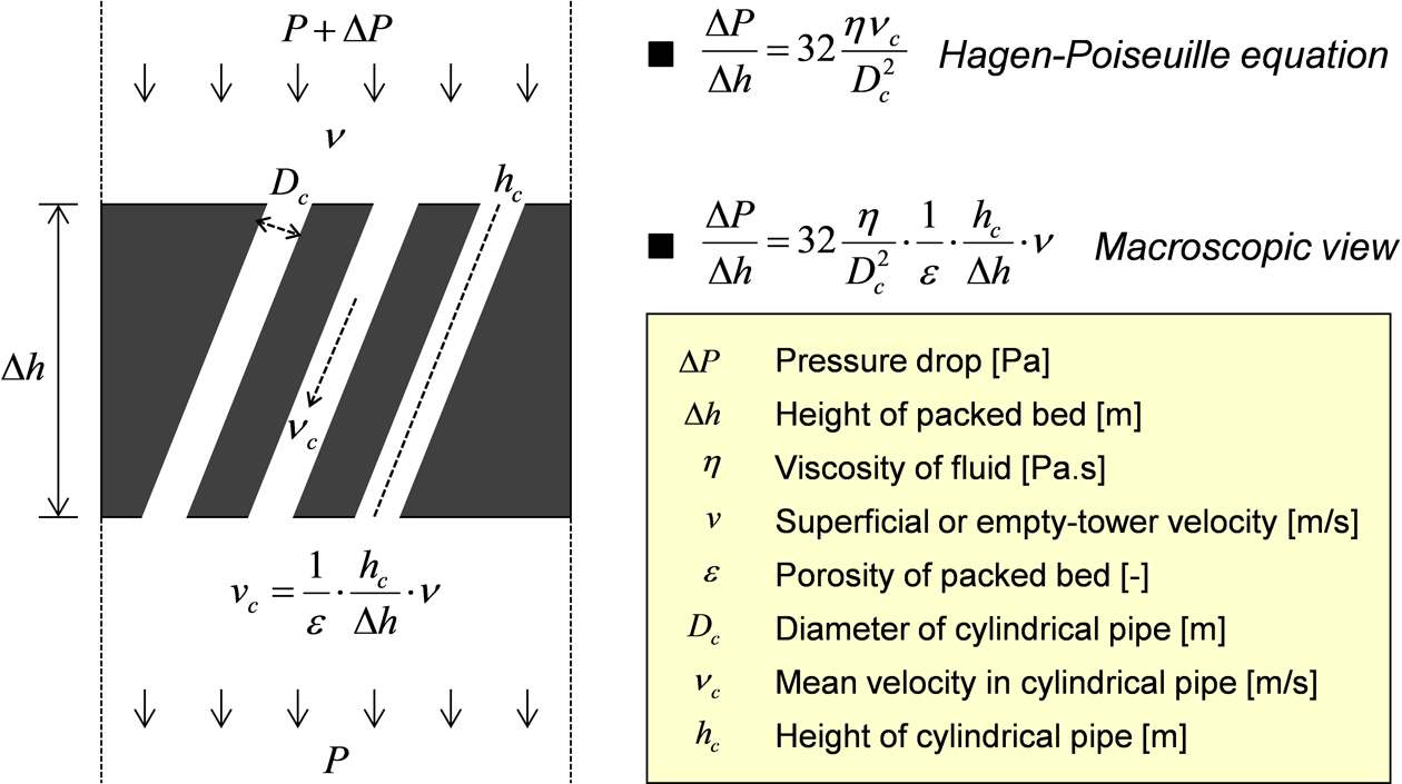
Capillary model for derivation of Kozeny–Carman equation.
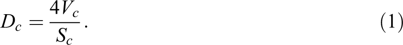
The diameter (Dc ) of the cylindrical pipe should be generalized and interpreted as the equivalent cylindrical pipe diameter that is defined as four times the volume (Vc ) of the capillaries per those surface area (Sc ). In this way, it can cover all kinds of capillaries, and those ones having very complicated and irregular cross sections along the same height (hc ) of cylindrical pipe
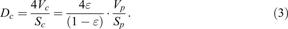
By shifting the viewpoint from capillary to particle 7,8 and through the definition of porosity (ε) in the packed bed system, the volume (Vc ) of the capillaries can be expressed in terms of the volume (Vp ) of the particles with the related function of porosity. And the surface area (Sc ) of the capillaries is simply substituted with the surface area (Sp ) of the particles, for both are essentially the same

When the particles are very analogous to sphere, the “volume to surface area of the particles” can be expressed in terms of the equivalent sphere diameter (D) that is defined as six times the volume (Vp ) of the particles per those surface area (Sp ). Thus, the equivalent cylindrical pipe diameter (Dc ) of the capillaries is completely shifted to the equivalent sphere diameter (D) of the particles

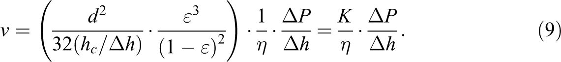
The Kozeny–Carman equation is another form of Hagen–Poiseuille equation, which is substituted with the equivalent sphere diameter (D) for the packed bed of particles:

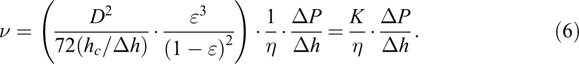
Equation (5) is rearranged and shortened with the permeability (K); the square of the equivalent sphere diameter (D), constant 72 and the tortuous degree in denominator, and the function of porosity. Furthermore, Kozeny–Carman equation can be more simply expressed in terms of the multiplied constant (150 or 180) by the empirical tortuous degree in the range of 2.0–2.5 7,8 :
Kozeny–Carman equation for packed bed of fibers
The Kozeny–Carman equation for the packed bed of fibers can be derived from the step of the “volume to surface area of the particles”. It is now expressed in terms of the fiber diameter (d) and length (l) instead of the equivalent sphere diameter (D):

Due to the fact that the fiber diameter (d) is very small compared to the fiber length (l), the “volume to surface area of the fibers” converges into a quarter of the fiber diameter (d). Also, it is explained by the terms of the equivalent cylinder diameter that is defined as four times the volume (Vp ) of the particles per those surface area (Sp ) by neglecting the surface areas of top and bottom:

Eventually, the Kozeny–Carman equation for the packed bed of fibers consists of the constant 32, which is different from 72 for the packed bed of particles (analogous to sphere). The minimum tortuous degree is 1 that is assigned for the parallel direction to the fiber arrays well aligned and of no channeling effect:
Controllable parameters in Kozeny–Carman equation
For the impregnation with thermoplastic matrix, heated tools are normally used to contact and pressurize the matrix for melting by heat transfer as well as for driving melt flow into the fiber reinforcement. This brings the negative and positive effects simultaneously. The pressurization decreases the porosity (ε) and the height (Δh ) of fiber reinforcement by the fiber compaction. At the same time, the viscosity (η) of thermoplastic matrix will decrease as the temperature is higher and with the shear thinning behavior of non-Newtonian fluids. Therefore, the pressure drop (ΔP ) raised by heated tools is not suitable to be an independent and a controllable parameter in Kozeny–Carman equation. The permeability (K) cannot be a controllable parameter as it is a kind of intrinsic parameter for a given fiber reinforcement, in which the tortuous degree should be above 1 and is not affected by porosity. Meanwhile, the maximum value of tortuous degree can be suggested around 5 as carefully chosen in Table 1 for the transverse direction to fiber arrays and especially for the more practical range of porosity above 0.5. The tortuous degree for the woven fabric (HexForce® 01038) as a transverse direction to fibers is experimentally determined as 3.5 (k 0=7 in the literature 14 ), which is a reduced value by the combination of macro and micro permeability (inter- and intrabundle).
Tortuous degree for transverse direction to fiber arrays.a
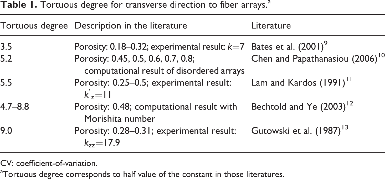
CV: coefficient-of-variation.
aTortuous degree corresponds to half value of the constant in those literatures.
The tortuous degree for a random directional fiber mat is supposed to be in the range of 2.0–2.5, similarly to the packed bed of particles. For example, Michaud et al.
15
had measured the permeability on the random glass fiber mat (Quadrant Plastic Composites AG (Switzerland)) and fitted by a power law, which was again verified with the two additional data by Merhi et al.
16
at the porosity of 0.82 and 0.92. When these are fitted by Kozeny–Carman equation, the corresponding values of tortuous degree are 1.0 and 2.0, respectively. The tortuous degree of 2.0 is more reasonable than of 1.0 at the porosity of 0.82, which might be distorted due to the fiber agglomeration having no actual flow inside. Arithmetically, this is when the equivalent cylinder diameter (or the degree of fiber agglomeration) is
New concept
MLH roving
The concept of MLH roving was invented for the better impregnation of fiber reinforcement, which is based on the minimized height (Δh ) of packed bed. In accordance to Kozeny–Carman equation, this will lead to a minimum flow length and fast impregnation. Namely, the MLH roving is a fiber roving separated evenly into several sublayers by thermoplastic films, which is manufactured by the sequential processes of spreading, fixing, and folding 17 –19 as depicted in Figure 2. To make the MLH roving of PP/GF45 vol.% (70 wt%), the GF roving of Advantex® boron-free ECR (Owens Corning, Toledo, Ohio, USA) was spread to 20 mm width; the GF roving is a single-end roving of PP compatible chemical sizing and has a linear density of 2400 TEX (g km−1) with 4000 fibers of 17 µm diameter. On both sides (top and bottom) of the spread GF roving, the PP films were thermally fixed by a double belt press machine 20,21 ; the given thickness of PP film is made of POLYPRO® homo PP (Korea Petrochemical Ind. Co., Ltd, Korea) by adding the concentrated master-batch for coupling, heat stabilizer, and black color. It was folded once or twice.
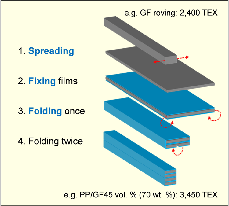
Manufacturing process of MLH roving. MLH: multilayered hybrid.
Thus, the MLH roving of PP/GF45 vol.% (70 wt%) has the linear density of 3450 TEX (g km−1) and consists of the same unit height of fiber reinforcement regardless of the widths, for example, 20 mm without folding, 10 mm by folding once, and 5 mm by folding twice; its unit height of fiber reinforcement is sufficiently minimized and corresponds to the 1000 fibers in 5 mm width. Furthermore, the MLH roving is flexible enough to make woven fabrics and more cost-effective in weaving processes, having the higher linear density than the typical GF roving of 1200 TEX for organic sheets (TEPEX) or commingled roving (TwinTEX) of 1870 TEX. The MLH roving is very comfortable in handling because its fibers are wrapped with thermoplastic film.
One of the specific benefits using the continuous fiber-reinforced materials is the unbalanced (anisotropic) reinforcement to optimize the intended performance of the final products. The unbalanced (2/1) woven fabric is the type of double reinforcement in warp to weft like using the MLH roving of 5 mm width with 5 picks per inch for warp and of 10 mm width with 2.5 picks per inch for weft (Figure 3), which is more stable and tighter fabric than made by the conventional way of spacing in weft with MLH roving of 5 mm width. Naturally, it is also possible to make the more unbalanced (4/1) woven fabric using the MLH roving of 20 mm width in weft. The weaving density was set in a way that one woven ply will lead to a fully impregnated plate of 0.6 mm thickness. The woven fabric of MLH roving has the lower risk of poor impregnation because of the outer films at every crossing point of warp and weft and of the outward flow behavior from the inner layers by pressurization not limited by the fiber compaction.
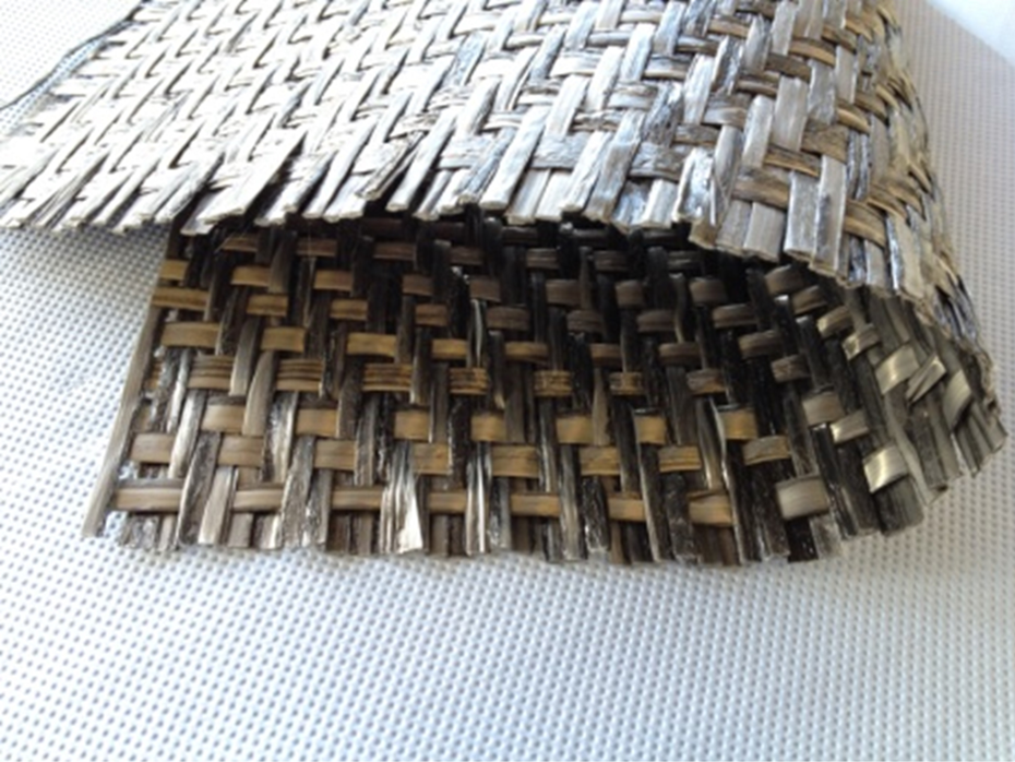
Unbalanced (2/1) woven fabric with twill pattern made of MLH roving. MLH: multilayered hybrid.
Newly derived spreading equation
The spreading methodology is based on the very simple principle that every fiber has the same path length by a properly designed curvature on the spreading support, like in the schematic diagram of Figure 4. Thus, the spreading process implies that the fibers are seeking each of those comfortable positions on the spreading support to keep the same path length and gradually edging away from the center line. Against the damages caused by excessive tension on fibers, it is better to weaken the firming agent in fiber rovings with the help of air flow 22 or by thermal and chemical ways.
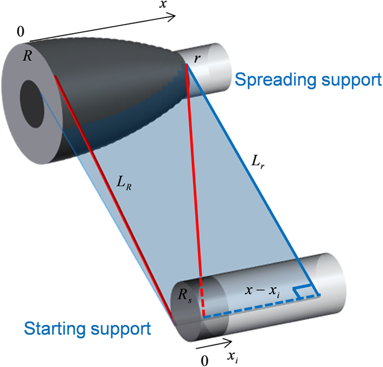
Schematic diagram for newly derived spreading equation.
The spreading equation in the patent of Bates and Charrier 23 has the restriction that every fiber is starting from a point. But from a practical point of view, it would be better to take into account the half width (xi ) before spreading and the radius (Rs ) of the starting support as depicted in Figure 4. Although the spreading equation is getting complex, this can prevent the serious center splitting problem on the spreading support, which is caused by the excessive curvature and cannot be recovered by itself. Accordingly, as shown in Figures 4 and 5, the path length of the center line is the sum of a tangent length (LR ) intersecting supports and continuing two arc lengths within the boundary of the horizontal distance (S). Also, in the same way, the path length of the arbitrary line is the sum of a diagonal tangent length intersecting supports from the hypotenuse of Pythagoras’s theorem and continuing two arc lengths in parallel to the center line. For reasons of convenience, the spreading apparatus was specified by 100 mm for the horizontal distance (S), 20 mm for the vertical distance (H), 3 mm for the radius (Rs ) of the starting support, and 13 mm for the radius (R) of the spreading support at the center line. Then, the tangent length (LR ) intersecting the supports at the center line and its acute angle (θR ) with the vertical line can be calculated as 100.72 mm and 69.66° by the following two trigonometric relations. Thus, the path length of the center line is settled as 106.40 mm by adding the two arc lengths:
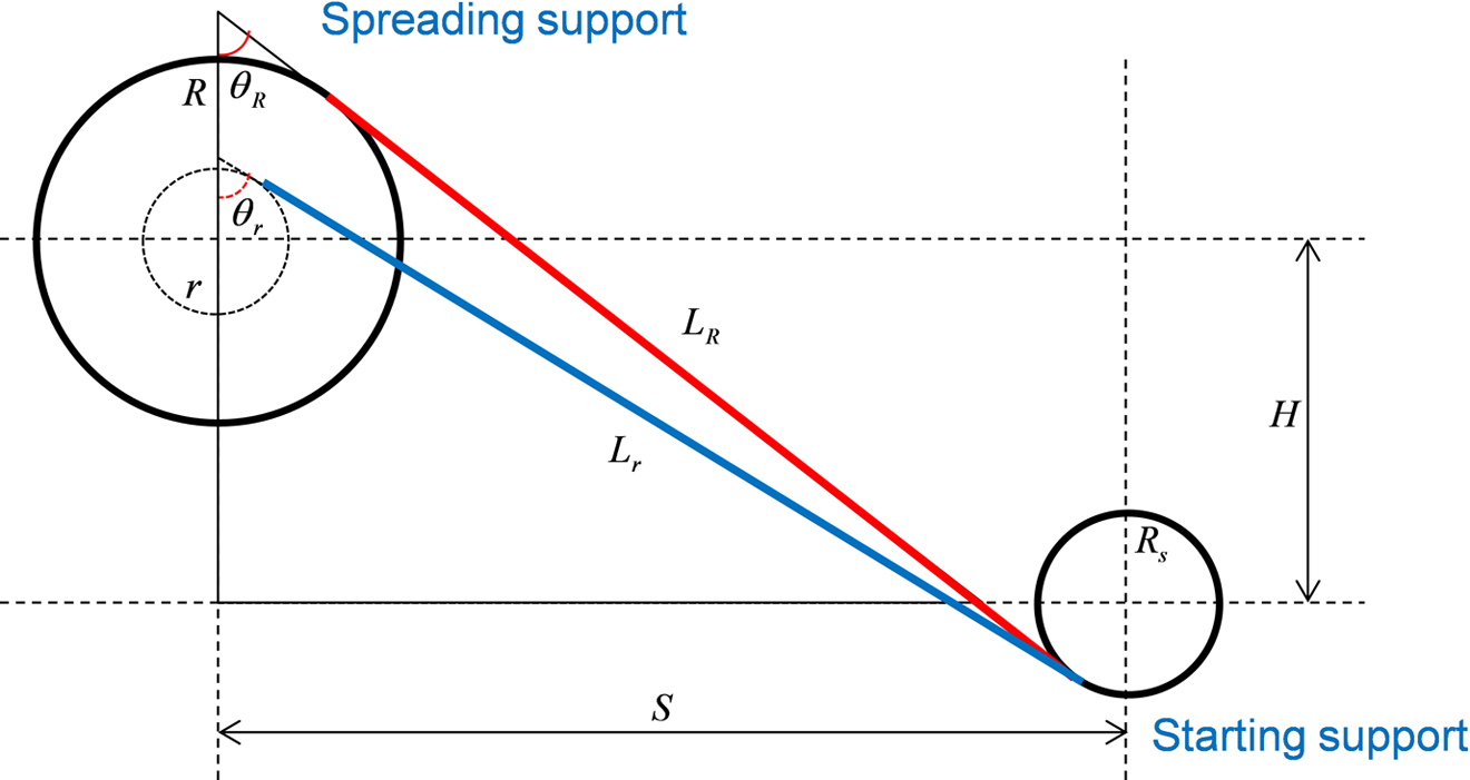
Cross sectional diagram of spreading apparatus at center line.


Eventually, the radius (r) of the spreading support at ±x position is determined by a process of iteration to keep the same path length of 106.40 mm, depending on the designed widths of before and after spreading; of course, it influences on the tangent length (Lr ) intersecting the supports at ±x position and its acute angle (θr ) with the vertical line. If the widths are designed to spread from 10 mm to 20 mm, the radius (r) of the spreading support at ±10 mm position is determined as 12.65 mm having the ratio (r/R) of 97.3%, so that the curvature on the spreading support is 7.0 m−1. But, in the case of starting from a point as proposed by Bates and Charrier, 23 the corresponding radius is 11.45 mm with the ratio (r/R) of 88.1%, and the curvature of 30.3 m−1. So, for the stable spreading like in Figure 6, the newly derived spreading equation is strongly recommended to prevent the center splitting problem by excessive curvature.
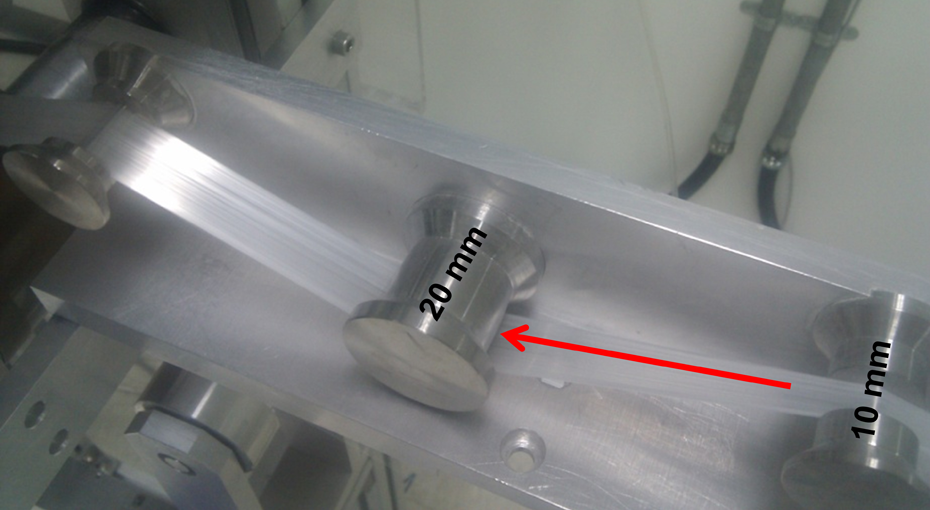
Stable spreading from 10 mm to 20 mm width.
Moreover, it is preferred to spread step by step rather than at a stroke. The spreading at a stroke from 5 mm to 20 mm width will be done by the curvature of 15.8 m−1 on the spreading support, whereas the step-by-step spreading is done by the smaller curvatures of 7.0 m−1 on each of the two spreading supports; for example, from 5 mm to 10 mm width and then from 10 mm to 20 mm width. Table 2 summarizes the designed geometries based on the newly derived equation.
Comparison in design of spreading apparatus.a
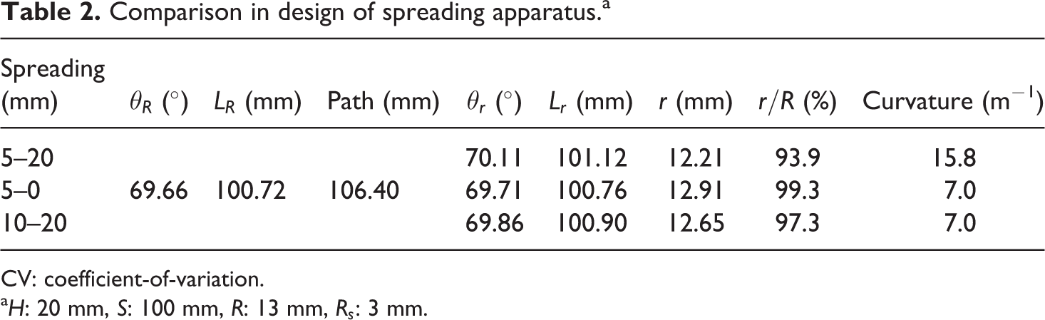
CV: coefficient-of-variation.
a H: 20 mm, S: 100 mm, R: 13 mm, Rs : 3 mm.
Performance
Verification on impregnation quality
The impregnation quality was verified on the plates that had been impregnated and consolidated by the CCM machine at IVW GmbH (Germany), considering the conditions of mass production. As depicted in the process diagram of Figure 7, the CCM process is based on the principle of the repeated pressurization for quasi-continuous impregnation, accompanying the heating and cooling zones. Here, the pressure is applied with the aim of heat transfer and driving melt flow into the reinforcement, while the pressure release is to give a chance of moving the material along the process line.
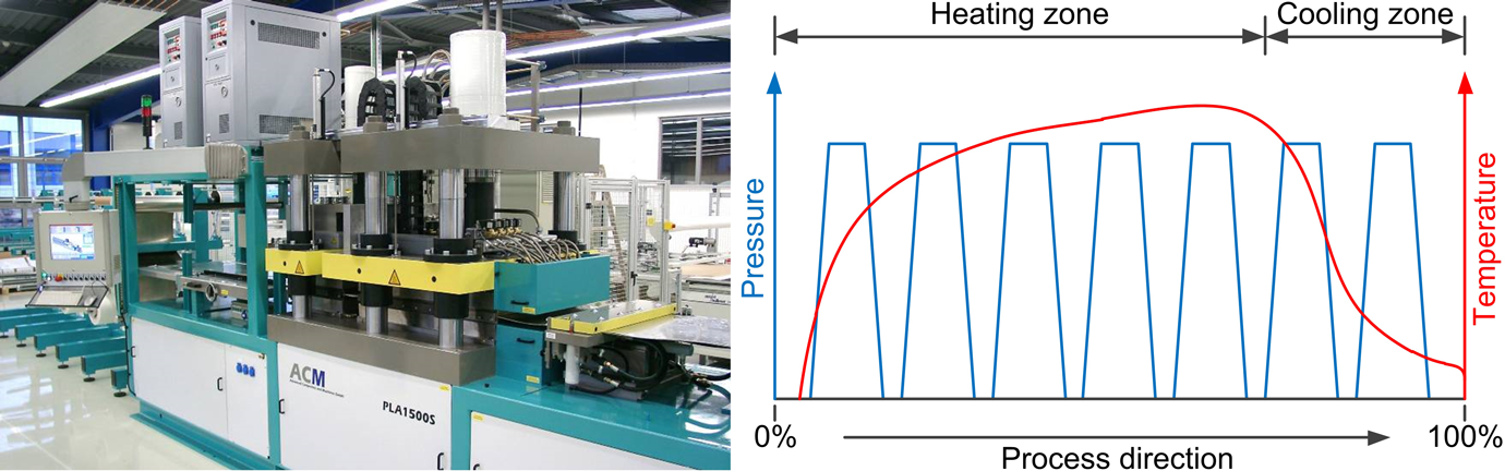
CCM machine at IVW GmbH and its process diagram. CCM: continuous compression molding.
The five plies of the unbalanced (2/1) woven fabric made of PP/GF45 vol.% (70 wt%) MLH roving was loaded to the CCM machine running at 10 m h−1 line speed and 25 bar pressure. Only the influence of temperature was investigated at 190, 210, 230, and 250°C. The impregnation quality was quantified by the three-point bending test for class III material in ISO14125, 24 because it can cover not only the tensile failure but also the compression and shear failures. In accordance with the test method, the dimensions of the test specimens were 3 mm thickness, 25 mm width, and 100 mm length. The test span length was 60 mm (20 times the specimen thickness). The three-point bending test was performed with the speed of 2.0 mm min−1 (equivalent to the strain rate of 0.01 min−1 on the outer surface of specimen) and within the valid strain range of 3% as defined for small deflection, using the load cell of 5 kN. The design of experiments, in each of the impregnation temperatures, was made up of the two bending directions (on top and bottom sides) to check the additional information whether the impregnation quality is symmetric or asymmetric. Each test set consisted of 10 specimens, which had been machined in the major and minor directions of the unbalanced (1/2) reinforcement. After the bending test, every outlier was excluded through the verification with 95% probability on each of the flexural properties. The statistical comparisons between the bending directions were done by single-factor analysis of variance (ANOVA) with 95% confidence level; when the resultant p value is higher than 0.05, there is no significant difference between the bending directions.
Representative values for major direction
With respect to bending direction, all the flexural properties in major direction (Table 3) were symmetric except for the flexural stain at 190°C (1.43% on top side and 1.64% on bottom side). The coefficient-of-variation (CV) is the ratio of the standard deviation to the mean, which is expressed as a percentage.
Flexural properties with impregnation temperature (major direction).a
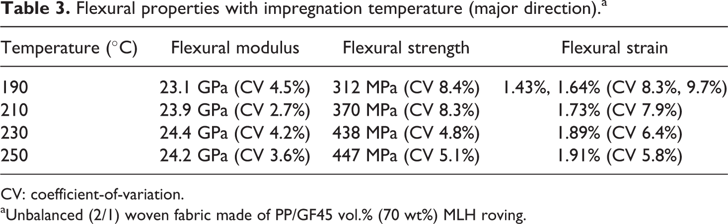
CV: coefficient-of-variation.
aUnbalanced (2/1) woven fabric made of PP/GF45 vol.% (70 wt%) MLH roving.
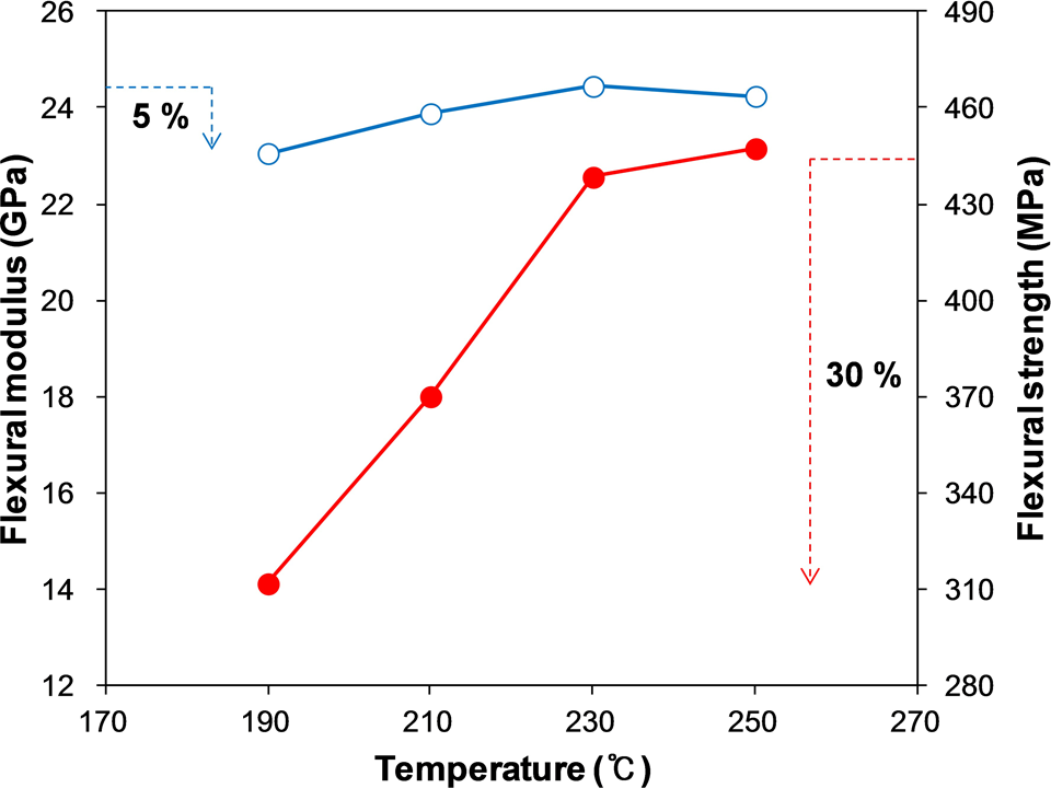
Another statistical comparison was done between the temperatures by single-factor ANOVA with 95% confidence level. Of those results, the p values between 230°C and 250°C are all sufficiently higher than 0.05. Accordingly, by merging of the two temperatures, the representative flexural properties for major direction are suggested as 24.3 GPa in modulus, 443 MPa in strength, and 1.90% in strain (Table 4). The flexural modulus of 24.3 GPa is a very reasonable value, for it has very narrow CV of 3.9%, and for it is at 95% level of the theoretical value; calculated by the rule of mixtures as the major direction of the unbalanced (2/1) layup 25,26 with the modulus of 1.7 GPa for PP 27 and 80.5 GPa for GF. 28 As graphically shown in Figure 8, the flexural properties are converging to each of the specific values. In the given range of impregnation temperature, the falling off from the representative value is 5% in modulus, 30% in strength (the most sensitive one), and 19% in strain. This is deeply related to the flattened voids in the shape of cracks as shown in the cross-sectional view of the plate impregnated at 190°C (Figure 9) but no longer at 250°C (Figure 10).
Representative flexural properties (major direction).a
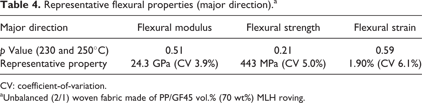
CV: coefficient-of-variation.
aUnbalanced (2/1) woven fabric made of PP/GF45 vol.% (70 wt%) MLH roving.
Variations in modulus and strength with impregnation temperature.
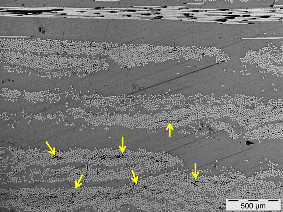
Cross-sectional view of plate impregnated at 190°C.
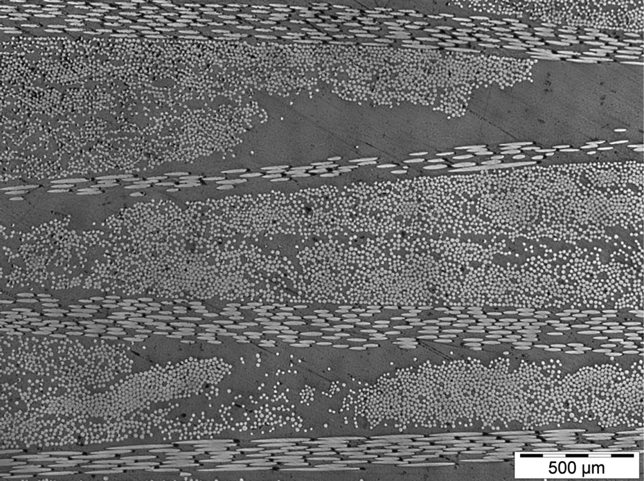
Cross-sectional view of plate impregnated at 250°C.
To efficiently characterize the stress–strain behavior, the persistence (or bias) degree was used as the ratio of the experimental strength to the modulus-based strength (modulus times strain) 29 ; it is 100% if a stress–strain curve perfectly follows the straight line determined by its modulus. The persistence degree gradually increased with the impregnation temperature, such as 88% at 190°C, 90% at 210°C, 95% at 230°C, and 96% at 250°C to be close to the straight stress–strain curve.
Variation in minor direction
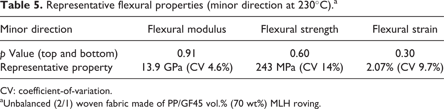
As summarized in Table 5, the representative flexural properties for minor direction are suggested as 13.9 GPa in modulus, 243 MPa in strength, and 2.07% in strain at the impregnation temperature of 230°C. Of course, there is no significant difference between the bending directions according to the statistical comparison by single-factor ANOVA with 95% confidence level. The flexural modulus of 13.9 GPa is also a very reasonable value, for it has very narrow CV below 5% and for it is at 97% level of the theoretical value calculated by the rule of mixtures. But the other CV values were two and three times wider, which seems to be somewhat related to the waving of fibers as depicted together with the sampling position in Figure 11.
Representative flexural properties (minor direction at 230°C).a
CV: coefficient-of-variation.
aUnbalanced (2/1) woven fabric made of PP/GF45 vol.% (70 wt%) MLH roving.
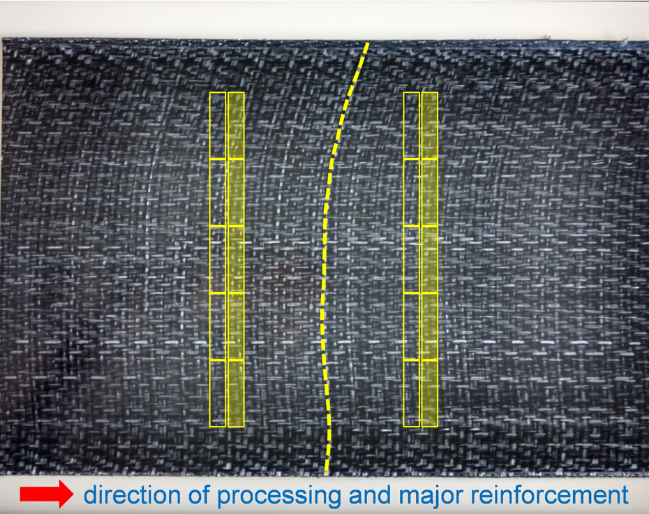
Sampling position and waving of fibers in minor direction.
The transverse direction of the CCM process is at higher risk of the waving of fibers due to no applied tension. Also, the waving of fibers is caused by the dragging to load the fabrics into the machine as well as by the backward flow of melted resin during impregnation. The behavior of the stress–strain curves for the minor direction can be classified into three types as shown in Figure 12, whereby the numbers of each type are 7, 6, and 7 of 20 specimens. Type 1 is the quite normal behavior that has the strain around 2% and the persistence degree around 90%. It is very similar to the behavior of the major direction. Type 2 is named as the sudden-drop behavior that has the same level of persistence degree around 90% but shorter strain. The sudden-drop behavior might be related to the crimp straightening. The crimp of the minor direction (10 mm width MLH roving) is higher than of the major direction (5 mm width MLH roving), for the MLH roving of 10 mm width is more flexible and for there is no tension applied to the minor direction during impregnation. Type 3 is named as the multilevel-drop behavior that has the same level of strain but lower persistence degree around 75%. It might be related to the misalignment due to the waving of fibers during and before impregnation.
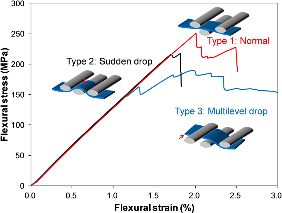
Three types of stress–strain curves for minor direction.
Conclusion
The new manufacturing concept named MLH roving was invented in the form of a fiber roving separated evenly into several sublayers by thermoplastic films, which is manufactured by the sequential processes of spreading, fixing, and folding. This concept is considering commercial aspects and also based on the minimized height (Δh ) of packed bed in Kozeny–Carman equation chosen as a controllable parameter rather than the others, in which the permeability was expressed in terms of the fiber diameter (d), constant 32 (not 72) and the tortuous degree in denominator, and the function of porosity.
Especially, the center splitting problem on the spreading support was prevented by the newly derived spreading equation taking into account the half width before spreading and the radius of starting support. The unbalanced (2/1) woven fabric made of PP/GF45 vol.% (70 wt%) MLH roving was impregnated and consolidated by the CCM machine running at 10 m h−1 line speed and 25 bar pressure, with different temperatures. Statistically, the representative flexural properties were suggested as 24.3 GPa in modulus, 443 MPa in strength, and 1.90% in strain for the major direction; all the CV values are in the moderate range of around 5%. But, in the case of minor direction, the CV values of strength and strain are three and two times wider. This can be explained by the two additional types of the stress–strain behaviors, caused by the waving of fibers due to no tension applied in minor direction; named as the sudden drop behavior by the crimp straightening and the multilevel drop by the misalignment. Inherently, the MLH roving holds the variety in processing like commingled roving and the variety in material configuration like organic sheet.
Footnotes
Acknowledgements
The authors would like to acknowledge that the MLH roving was produced and woven by Large Co., Ltd (Korea) holding the patent right with LG Hausys Ltd (Korea).
Declaration of conflicting interests
The author(s) declared no potential conflicts of interest with respect to the research, authorship, and/or publication of this article.
Funding
The author(s) received no financial support for the research, authorship, and/or publication of this article.