
Abstract
Chemically modified sisal fibers are used to reinforce high-density polyethylene to seek applications in electrical appliances and car industry requiring light composite materials with superior mechanical and dielectric properties. Conventional methods of chemical modification using sodium hydroxide are used together with new modifications using benzoyl chloride and benzoyl peroxide in order to improve the compatibility between the hydrophilic fiber surface and the hydrophobic polymer matrix. Mechanical properties have been improved by more than 50%, and improved thermal and electrical properties are achieved using the resulting microcomposite material. The resulting microcomposite can accordingly find its way in electrical appliances and in the car industry replacing metallic parts especially those requiring high dielectric constant and superior mechanical properties.
Introduction
The term “natural fibers” covers a broad range of vegetable, animal, and mineral fibers. However, in the composites industry, it usually refers to wood fiber and agro-based, leaf, seed, and stem fibers. These fibers often contribute greatly to the structural performance of the plant, and, when used in plastic composites, they can provide significant reinforcement. 1 –4 Recently, there has been a resurgence of interest in the use of these natural fibers as reinforcements in plastics due to their good mechanical performance and perceived environmental advantages. 1 Currently, many types of natural fibers 5 have been investigated for use in plastics including flax, hemp, jute straw, wood, rice husk, wheat, barley, oats, rye, cane (sugar and bamboo), grass, reeds, sisal, coir, water, hyacinth, pennywort, kapok, paper mulberry, banana fiber, pineapple leaf fiber, papyrus, and others. These natural fibers have an advantage over synthetic fibers in that they are less expensive, abundantly available from renewable resources, and have a high specific strength.
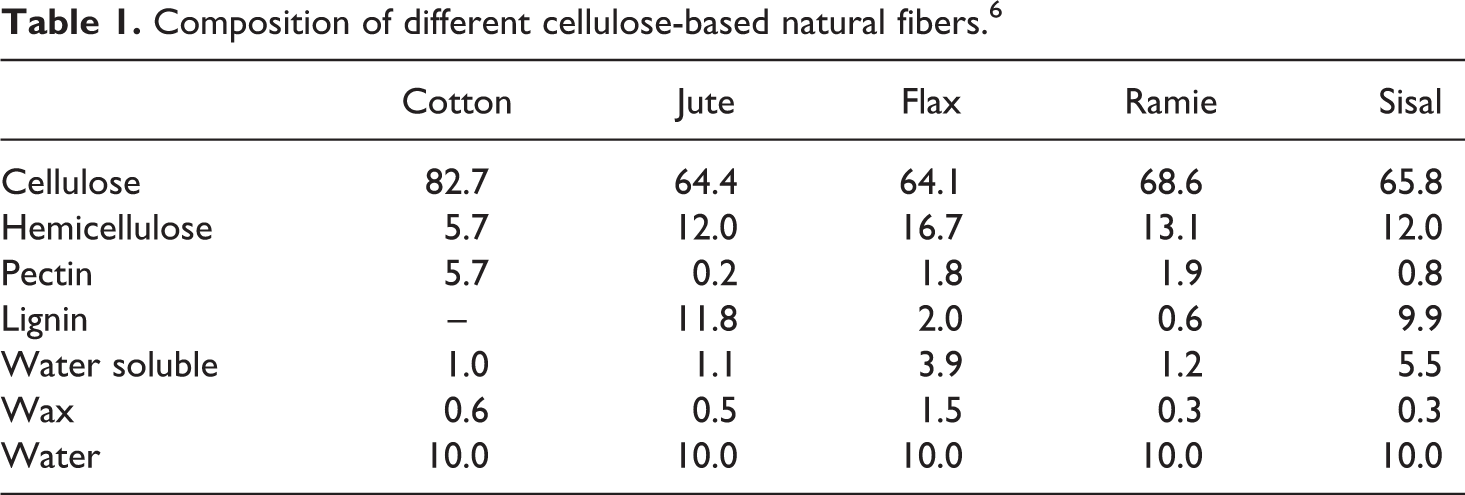
Natural fibers are complex in structure. They are generally lignocellulosic, consisting of helically wound cellulose microfibrils in an amorphous matrix of lignin and hemicellulose. Table 1 lists some natural fibers and their chemical constituents. Mechanical properties are dominated by the cellulose content and microfibril angle. A high cellulose content and low microfibril angle are desirable properties in a fiber to be used as reinforcement in polymer composites.
Composition of different cellulose-based natural fibers. 6
Sisal fiber is one of the most widely used natural fibers and is very easily cultivated. It has short renewal time and grows wild in the hedges of fields and railway tracks. 7 Nearly 4.5 million tons of sisal fibers are produced every year throughout the world. Tanzania and Brazil are the two main countries producing fiber. 8
Although sisal fiber is one of the most widely used natural fiber, a large quantity of this economic and renewable resource is still underutilized. At present, sisal fiber is mainly used as ropes for the marine and agriculture industry. 7 Other applications of sisal fiber include twines, cords, upholstery, padding and mat making, fishing nets, fancy articles such as purses, wall hangings, table mats, and so on. 9 A new potential application is for manufacture of corrugated roofing panels that are strong and cheap with good fire resistance. 10
In a composite, the fiber, as well as the matrix, retains their physical and chemical identities but still provides a combination of properties that cannot be achieved with either of the constituents alone. In general, the fibers play the role of load bearer. The matrix, while keeping the fibers in the desired location and orientation, acts as a load transfer agent and protects the fibers from external conditions such as chemicals, heat, and moisture.
One difficulty that has prevented a more extended utilization of the natural fibers is a lack of a good adhesion to most polymeric matrices. The hydrophilic nature of natural fibers adversely affects adhesion to a hydrophobic matrix, and as a result, it may cause a loss of strength. To prevent this, the fiber surface has to be modified in order to promote adhesion. 11
Several methods to modify the natural fiber surface have been proposed, which include the graft copolymerization of monomers onto the fiber surface, the use of maleic anhydride copolymers, alkyl succinic anhydride, and stearic acid. It has also been reported that the use of coupling agents such as silanes, titanates, zirconates, and triazine compounds also improves fiber-matrix adhesion. Furthermore, it is also known that pre-impregnation of the fiber with the polyolefin solution will also improve adhesion. 12
Natural fibers also improve mechanical performance of the resulting composite such as stiffness and strength without increasing the density or cost too much. 1 The characteristics of natural fibers–reinforced plastics have been studied by several authors; Hu and Lim 13 investigated that alkali treatment significantly improved the tensile properties of hemp fiber–reinforced polylactic acid compare to those untreated. They found that the composites with 40% volume fraction of alkali-treated fiber have the best tensile properties.
Li et al. 14 studied flax fiber–reinforced polyethylene biocomposites. In the study, flax fibers, containing 58 wt% of flax shives, were used to reinforce high-density polyethylene and linear low-density polyethylene. Five surface modification methods, such as alkali, silane, potassium permanganate, acrylic acid, and sodium chlorite treatments, were employed to improve the interfacial bonding between fibers and matrix. The experimental results showed that the tensile strengths were increased after surface modifications. Among these surface modification techniques, acrylic acid was found to be a relatively good method in enhancing tensile properties of both flax/high-density polyethylene (HDPE) and Linear Low Density Polyethylene (LLDPE) biocomposites. 14
One of the largest areas of recent growth in natural fiber plastic composites is the automotive industry, particularly in Europe, where natural fibers are advantageously used as a result of their low density and increasing environmental pressures. Most of the composites currently made with natural fibers are press molded. 1,15
This work focuses on sisal microfibers treated using three different chemical methods to enhance the natural fiber compatibility with the polymer (HDPE) and improve thermal, electrical, and mechanical properties of the resulting microcomposites. The modified sisal fibers were mixed in a HDPE matrix before the tensile specimens were fabricated by hot press molding.
The effectiveness of the fiber’s chemical treatments was evaluated thorough changes into mechanical, thermal, and electrical properties of composites. Modified sisal fibers were added at different fiber content (10, 20, and 30 wt%). Through this, the effects of chemical treatment can clearly be evaluated.
Sisal fibers were treated by using (i) a sodium hydroxide aqueous solution (NaOH), (ii) benzoyl chloride, and (iii) benzoyl peroxide to study the effect of adding chemically modified fibers to the neat polymer at different fiber content.
Materials and experimental methods
HDPE was supplied by Oriental Petrochemicals Company, Egypt, in the form of homopolymer pellets. It has a density of 0.9 g cm−3 and melt flow index of 1.16 g/10 min at 230°C using 2.16 kg standard load.
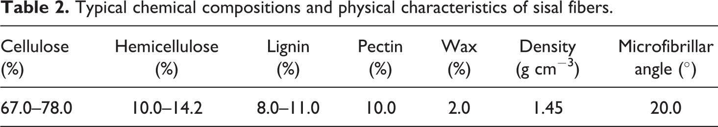
Sisal fibers were used in the form of short fibers (6 mm long). The fibers were supplied by Canal Company for Ropes, Cairo, Egypt. The average diameter of the fibers was equal to 180 µm approximately. Typical chemical compositions and physical characteristics of sisal fibers are given in Table 2.
Typical chemical compositions and physical characteristics of sisal fibers.
Sodium hydroxide was obtained from Adwic (Egypt) in the form of odorless white solid. Benzoyl chloride was supplied from Loba Chemie PVT (India) in the form of colorless liquid. Benzoyl peroxide was supplied from Oxford Laboratory (India) in white pellets form. It has melting point of 102–105°C. Acetone, ethanol, and xylene used as the solvents for the fiber treatment are obtained from El-Nasr Pharmaceutical Chemicals Company (Egypt).
Preparation of modified sisal microfibers
The fiber was washed thoroughly with water and dried in an air oven at 80°C for 4–6 h before being chopped into the desired length (6 mm) for fiber treatment and composite preparation. This allows us to compare our results to previously published data and to use fibers with specifications comparable to those used for different industrial applications.
Surface modification of sisal fiber by alkali treatment
Chopped sisal fibers were treated with 2% solution of NaOH for 1 h, in which fiber-to-solution weight ratio was 1:25. The fibers were washed thoroughly with water to remove the excess of NaOH on the fibers. Fibers were dried in an air oven at 60°C for 24 h.
Surface modification of sisal fiber by benzoyl chloride treatment
A fixed amount of this fiber (fiber-to-solution weight ratio was 1:25) was soaked in 18% NaOH solution for 30 min, filtered, and washed with water. The treated fiber was suspended in 10% NaOH solution and agitated well with benzoyl chloride. The mixture was kept for 15 min, filtered, washed with water, and dried between filter paper. The isolated fiber was then soaked in ethanol for 1 h to remove the unreacted benzoyl chloride and finally washed with water and dried.
Surface modification of sisal fiber by benzoyl peroxide treatment
The alkali-treated fibers were socked with a 6% solution of benzoyl peroxide in acetone for 30 min. The solution was decanted, and the fibers were air-dried.
Preparation of the microcomposite
A sisal fiber content of HDPE/sisal fiber composite of 10, 20, and 30% w/w was chosen in order to determine the effect of the different surface treatments on its mechanical properties. The sisal fibers were incorporated into the HDPE matrix, at 180°C using a Brabender internal mixer (type: EPL-V7752, Duisburg, Germany). The mixing process was performed at 180°C and at a rotor formulations speed of 60 r min−1 for 10 min. The resulting material was compression molded at a pressure of 1 ton using a Carver laboratory press and a temperature of 180°C for 10 min. The specimens for the mechanical test were obtained from these laminates according to ASTM standards. 16
Characterization of modified sisal fibers and the resulting microcomposite
FTIR of the sisal microfiber
The samples of sisal fibers were previously dried and grounded to powder and pressed with potassium bromide in disk format for the measurement, and the FRIR spectra were recorded on a Thermo Scientific Nicolet 380 spectrometer in the spectral range of 4000–400 cm−1.
Thermal analysis of the bare microfibers and the resulting HDPE microcomposite
The thermal decomposition of natural fibers was evaluated by thermogravimetric analysis (TGA) using Model TA-50, Shimadzu, Japan, on 5 mg sample, at a heating rate of 10°C min−1. TGA was conducted under a high-quality nitrogen atmosphere in order to avoid unwanted oxidation. 17
The thermal stability behavior of the neat HDPE and formulated HDPE/sisal composites was also measured by TGA as explained above.
Crystallization and melting behaviors of the neat HDPE and formulated HDPE/sisal microcomposites were measured by differential scanning calorimeter (DSC-50, Shimadzu, Japan) under nitrogen atmosphere at a heating rate of 10°C min−1. The melting enthalpies (ΔH m) and the crystallinity values were detected by differential scanning calorimetric (DSC) technique. The crystallinity values of the polymers were determined by using the following equation: 17

where ΔH
m is the melting enthalpy of the polymer, measured by using the area under the melting peaks, and Δ
Morphological analysis of the microfibers and the HDPE microcomposite
The morphologies of treated and untreated sisal fibers as well as the resulting microcomposite were studied by using scanning electron microscope (SEM) at an acceleration voltage of 30 kV (Model Philips XL 30). We studied the changes in the microfiber morphology before and after the treatment process. Prior to the measurement, the specimens were coated with gold.
Mechanical properties of the HDPE/sisal microcomposites
Mechanical tests including tensile, elongation at break, and elastic modules tests were performed a tensile testing machine (Model Z 010, Zwick, Germany) at a crosshead speed of 50 mm min−1, according to ASTM D-638 standards. Sheets were cut out to five individual dumbbell specimens by a steel die of constant width (0.4 cm). The thickness of the test specimen was determined by using a dial gauge. A bench mark of 15 mm length was marked on the working part of each specimen under test.
Electrical properties of the HDPE/sisal microcomposite
Test samples of 2 mm thickness and 5.2 mm diameter were used. Capacitance (C) was measured by using a Hewlett-Packard LCR Meter model 4274 A (Palo Alto, California, USA). The measurements were carried out at room temperature by varying the frequencies (50 Hz–5 MHz). Dielectric constant (ε) of the composite has been calculated by using the following relation 18 :
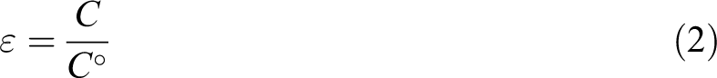
where
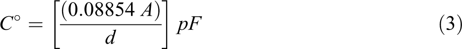
where A (cm2) is the area of the electrodes and d (cm) is the thickness of the sample.
Results and discussion
FTIR of sisal microfibers
Figure 1 illustrates the Fourier transforms infrared (FTIR) spectra of the untreated and treated sisal microfibers by different chemical methods. FTIR pointed out that the C–H in cellulose and hemicellulose stretched around 2920 cm−1 is present in all fibers. The carbonyl peak at 1730 cm−1 can be seen in the fibers not treated with alkali. A broad peak at 3432.88 cm−1 is also obvious due to bonded O–H groups in cellulose.
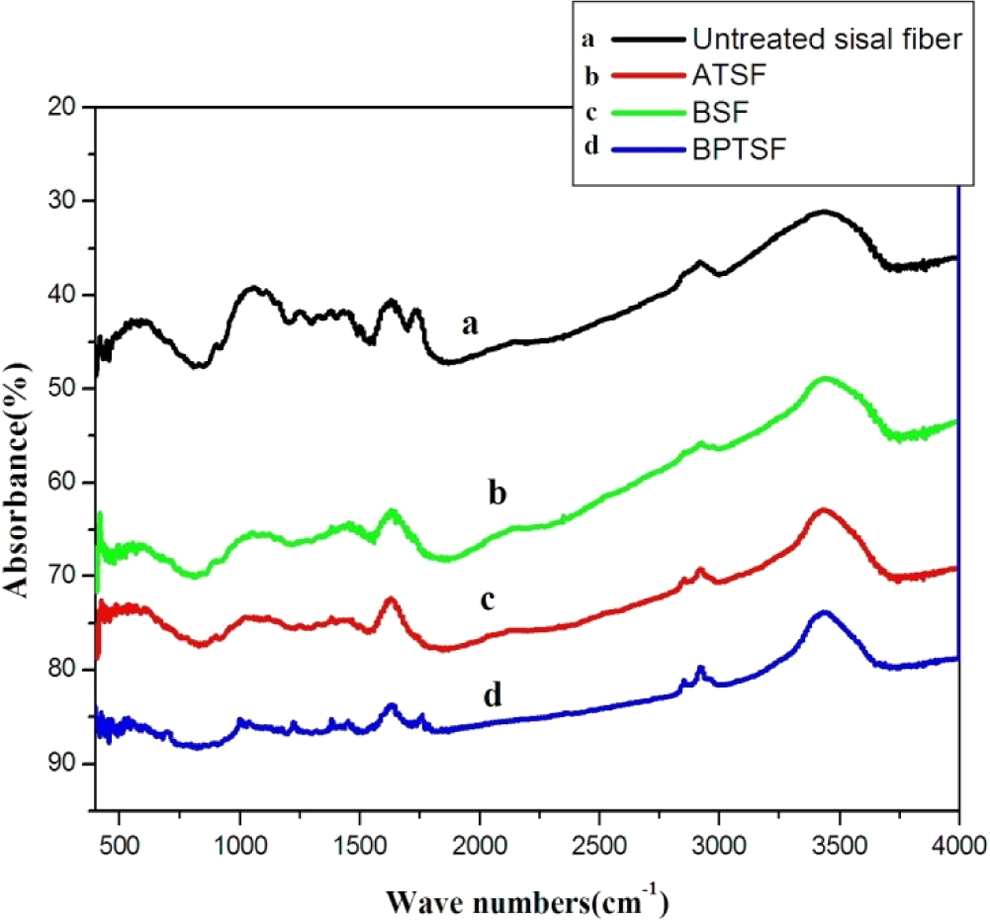
FTIR spectra of untreated and chemically treated sisal fibers. (a) untreated sisal fiber, (b) ATSF, (c) BSF, and (d). FTIR: Fourier transforms infrared; ATSF: alkali-treated sisal microfiber; BSF: benzoylated sisal microfiber; BPTSF: benzoyl peroxide–treated sisal fiber.
Alkali treatment of sisal microfiber surface can remove natural and artificial impurities and produce a rough surface topography. In addition, alkali treatment leads to fiber fibrillation, that is, breaking down the microfiber bundle into smaller microfibrils. This increases the effective surface area available for wetting by the matrix. Hence, increasing the microfiber aspect ratio caused by reduced microfiber diameter and producing a rough surface topography offer better fiber/matrix interface adhesion and increase in mechanical properties 19,20

After alkali treatment, these lignocellulosic microfibers can experience a significant weight loss due to the partial dissolution of hemicellulose, lignin, and pectin. They clearly identified that the band around 1730 cm−1, corresponding to hemicellulose, disappears when the microfibers were treated by dilute NaOH aqueous solution. 21
Benzoyl chloride–treated microfibers were initially alkaline pretreated in order to activate the hydroxyl groups of the cellulose and lignin in the microfiber. Here, we try to overcome the problem of compatibility by a new approach that is by benzoylating the microfibers, which makes the fiber more hydrophobic and compatible with polymer. The reaction between the cellulosic –OH group of natural fiber and benzoyl chloride may be shown as: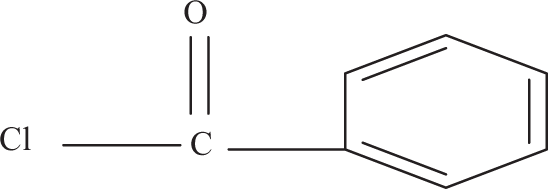
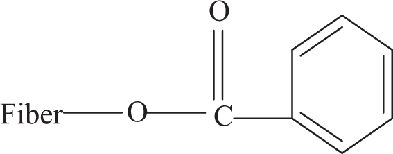

where, fiber –OH represents any hydroxyl group in the fiber cellulose components. 20
The benzoylated sisal microfiber (BSF) and benzoyl peroxide–treated sisal fiber (BPTSF) have a spectrum profile similar to that of the alkali-treated sisal fiber. After benzoyl chloride treatment, the band around 3444 cm−1 corresponding to O–H group and the C–H bond stretching at 2920 cm−1 appeared as well as the carbonyl group C=O and C–O group at 1659 and 1048 cm− 1.
For benzoyl peroxide treatment, the peak for O–H group stretching at 3432 cm− 1 and the peak at 2922 cm− 1 corresponding to aromatic C–H appear. Also, aliphatic C–H at 2853 cm− 1 and the carbonyl group C=O stretched at 1758 cm− 1 and C–O group at 1036 cm− 1 are obvious. All these results confirm the effective chemical treatment onto sisal fibers. 22
The function of peroxide treatment is that it can graft polyethylene (PE) onto the cellulose surface. The grafting reaction is a result of the peroxide-initiated free radical reaction between the PE matrix and cellulose fibers as shown below: 19


The hydrogen may be abstracted from O–H and C–H groups of the cellulose. In HDPE, the hydrogen abstraction may take place from the tertiary carbon atoms.
The following reactions may occur during the processing of composites: 1. Increase in molecular weight and cross-linking of the polymer matrix by the combination of macro-radicals of polyethylene:

2. Grafting of polyethylene onto cellulose fibers by combining cellulose and polyethylene radicals:

TGA of sisal microfibers
Thermogravimetric curves of treated and untreated sisal microfibers are given in Figure 2. The majority of natural fibers have low degradation temperatures at about approximately 200°C, which make them inadequate for processing with thermoplastics with processing temperatures above 200°C. Figure 2 shows the thermal decomposition of sisal microfibers which takes place in the temperature range of 250–750°C. The first weight loss of sisal microfibers occurs between 60°C and 100°C corresponds to the heat of vaporization of water in the sample. The second weight loss at about 230°C is due to thermal decomposition of hemicelluloses and the cleavage of glucosidic linkages of cellulose. 22,23
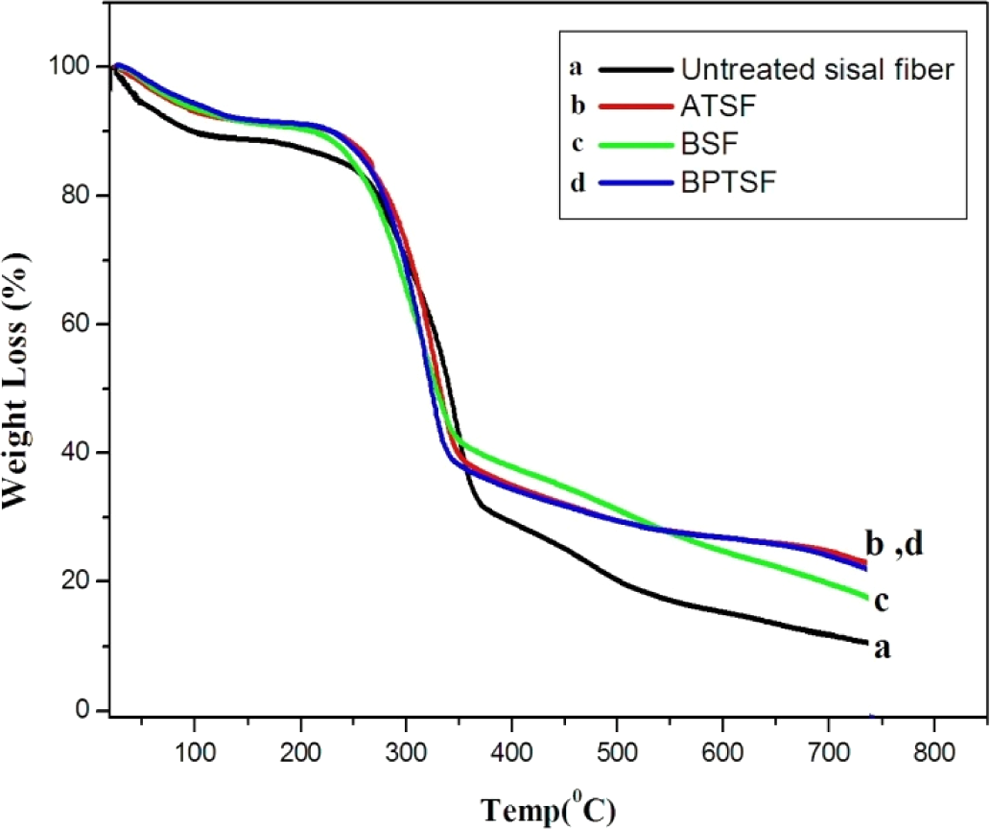
TGA patterns of untreated and treated sisal microfibers. TGA: thermogravimetric analysis.
DSC analysis of sisal microfibers
The DSC analysis of the untreated and treated sisal fibers as a function of temperature is shown in Figure 3. All curves for untreated sisal microfibers, ATSF, BSF, and BPTSF show endothermic peaks between 60°C and 100°C assigned to water loss. The large exothermic events that occur between 270°C and 350°C are assigned to the decomposition process of the major components of the sisal fibers (cellulose and hemicellulose degradation and the high temperature part correspond to lignin degradation). 22,23 Only the untreated sisal microfibers show two endothermic peaks at the higher temperature range indicating the presence of two distinct transitions corresponding to two different molecular weights of cellulose and hemicellulose. While all treated microfibers show only one peak indicating that the treatment process averages out different molecular weights existing in the natural fiber.
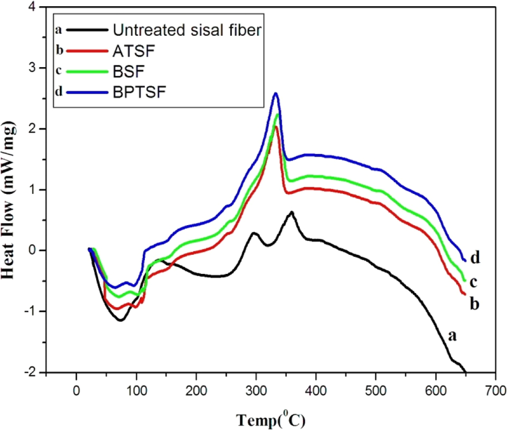
DSC patterns of untreated and treated sisal microfibers. DSC: differential scanning calorimetric.
Morphology of sisal microfibers
SEM provides an excellent technique to study the surface morphology of original and chemically modified sisal microfibers. It is observed that surface morphology of untreated sisal microfibers is different from the treated sisal microfibers. Figure 4 shows the SEM of raw and chemically treated sisal fibers. These micrographs clearly show that the original fiber surface is very smooth in comparison with treated fibers as it can be seen from Figure 4(a). This is probably due to the removal of low molar mass compounds, which occurs during treatment, leaving cavities on the surface. The high roughness of the fiber surface provides a larger number of anchorage points for the polymeric matrix, increasing the interaction between the components of the composite. 22 This will affect the reinforcement of the composite as will be shown later.
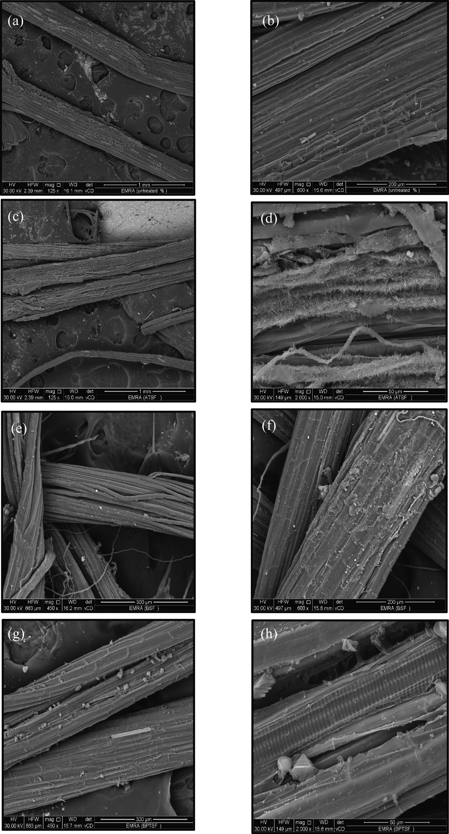
SEM micrographs of untreated sisal microfibers (a and b), ATSF (c and d), BSF (e and f), and BPTSF (g and h). SEM: scanning electron microscope; ATSF: alkali-treated sisal microfiber; BSF: benzoylated sisal microfiber; BPTSF: benzoyl peroxide–treated sisal fiber.
Characterization sisal fiber/HDPE microcomposites
Mechanical properties of HDPE reinforced with sisal microfibers
The tensile strength of the HDPE short sisal fibers composite as a function of the fiber loading is shown in Figure 5. It can be seen that the tensile strength of the HDPE matrix is approximately equal to 20.77 MPa, and the incorporation of the treated sisal microfibers results in an increase in the tensile strength. That improvement is also due to the weight percentage of microfiber content. In the case of alkali-treated sisal microfiber (ATSF) composites, the microfiber-reinforced polymer showed superior tensile properties than neat HDPE. This is due to the fact that alkali treatment improves the microfiber surface adhesion characteristics to the polymer by removing natural and artificial impurities, thereby producing a rough surface as show in SEM photomicrographs of ATSF.
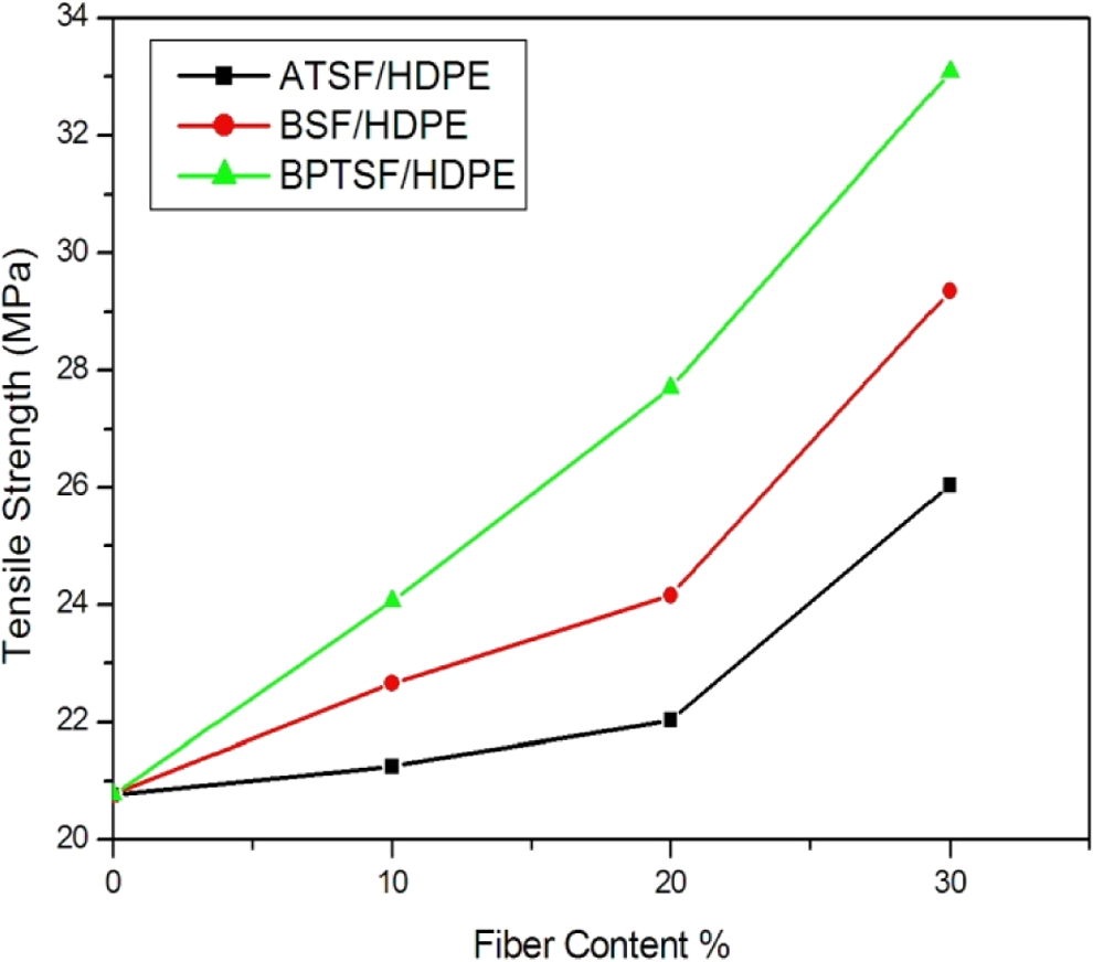
Tensile strengths of the microcomposites with different chemical treatment of microsisal fibers.
In addition, alkali treatment leads to microfiber fibrillation, that is, breaking down of the composite microfiber bundle into smaller microfibers. This increases the effective surface which is available for contact with the polymer matrix, hence promoting more HDPE/sisal microfiber interpenetration at the interface. 24
In the case of the BSF, the tensile strength of BSF/HDPE microcomposite increased by 41% (in the case of 30% fiber content), over the neat HDPE. This may be due to intrinsically increased strength of the microfibers and increased interfacial adhesion. The treatment produces a number of small voids on the surface of the microfiber that promotes mechanical interlocking between the microfiber and the polymer matrix. The reduction in hydrophilic nature makes the microfiber more compatible with hydrophobic matrix. The rough surface also improved the adhesion between microfiber and the HDPE matrix. 20
In the case of benzoyl peroxide–treated sisal microfiber (BPTSF), it showed the best improvement of tensile strength among the tested samples, and it reached to 33.08 MPa (increased by 59%) at microfiber loading of 30%. The increase in tensile properties offered by the peroxide-treated composites is due to the peroxide-initiated free radical reaction between HDPE and cellulose fiber as discussed above in equations (8) to (10). 24
The continuous increase in the tensile strength with increasing loading of sisal microfibers also shows that the microfibers are very well aligned within the polymer matrix giving progressive reinforcement of the material with increasing the loading percentage of the sisal microfibers. This is also clear in the hardness values obtained for the different samples. In general hardness of a composite depends on the distribution of the filler into the matrix. Usually, the presence of a more flexible matrix causes the resultant composites to exhibit lower hardness. Figure 6 shows the variation in shore D hardness values for treated short sisal microfiber/HPDE composite with the microfiber content. It is clear that the incorporation of treated sisal microfibers into the HDPE matrix reduced the flexibility of the polymer matrix resulting in more rigid composites. Hardness increased gradually with the increase in the microfiber content overcoming the brittle nature of lignocellulosic sisal microfiber.
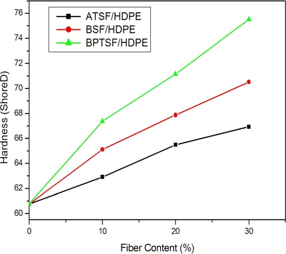
Hardness of the microcomposites with different chemical treatment of microsisal fibers.
The BPTSF/HDPE composite showed the best improvement of hardness among all the treated samples since it reached to 67.38 shore D by using 10% of BPTSF and 75.52 shore D by using 30% of BPTSF.
Thermal analysis of HDPE/sisal fiber microcomposite
Thermogravimetric analysis
The TGA curves of treated sisal fiber-HDPE microcomposites (not shown here) indicate that the thermal stability of all treated microcomposites is higher than that of the neat HDPE. The improved thermal stability of treated fiber microcomposites is associated with the superior thermal stability of treated microfibers. Another factor that contributes to the higher thermal stability of treated microcomposites is the improved microfiber/HDPE matrix interactions, which produce additional intermolecular bonding between the microfiber and the polymer matrix.
Figure 7 shows the thermogravimetric curves of HDPE, sisal micro fiber, and HDPE/sisal microcomposite containing 30% BPTSF fiber. The temperature range of the analysis was 250–700°C. For sisal microfiber, dehydration as well as degradation of lignin occurs in the temperature range of 60–200°C. HDPE decomposes at a temperature of 250°C, which is higher than that of the fiber, while the composite of 30% BPTSF/HDPE decomposed at about 450°C. Figure 7 reveals the fact that microfiber-filled system degrades later than the HDPE matrix, that is, the thermal stability of the composite is higher than that of the microfiber and HDPE matrix. This increased stability of composite compared to sisal microfiber is due to the improved microfiber matrix interaction.
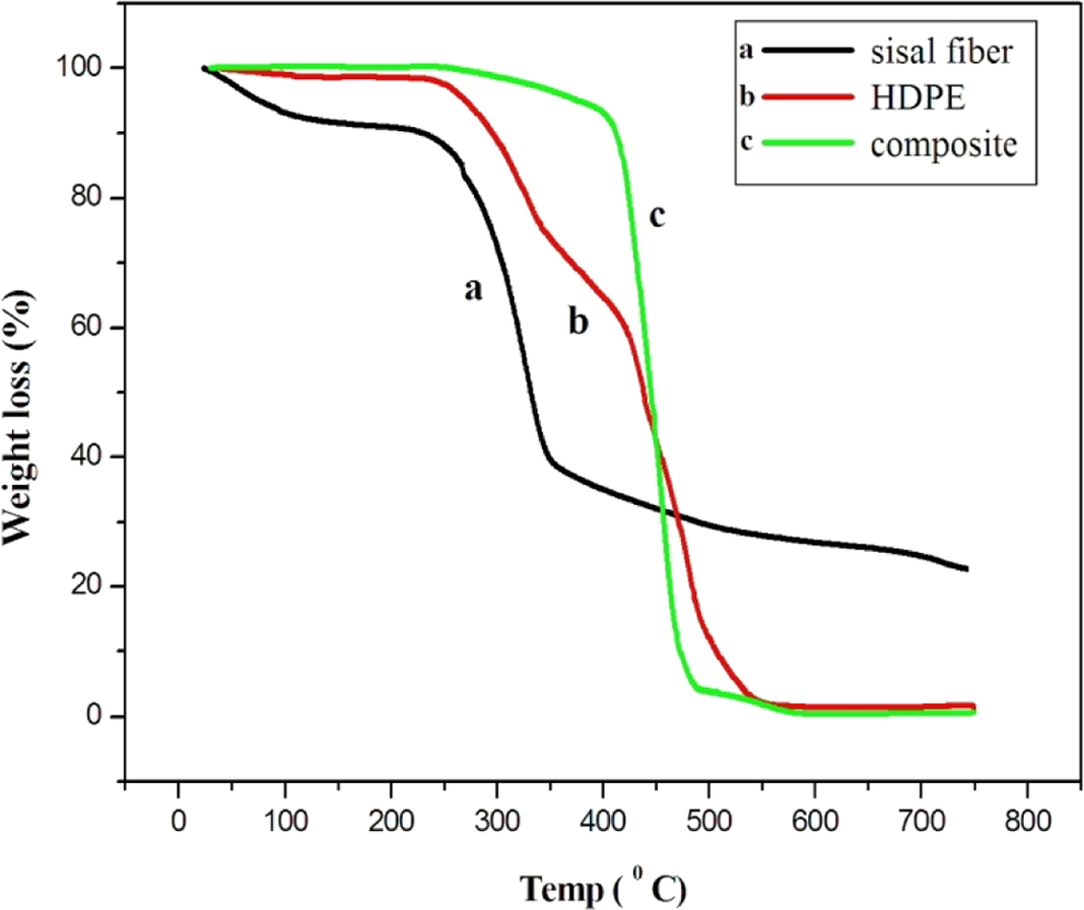
Thermogravimetric curves of (a) sisal fiber, (b) HDPE, and (c) BPTSF sisal fiber/HDPE composite containing 30% by weight of fiber. HDPF: high-density polyethylene; BPTSF: benzoyl peroxide–treated sisal fiber.
The presence of two degradation peaks for the HDPE-based composites containing treated sisal microfiber indicates that the degradation takes place at two steps. The first peak appeared at 250°C associated mostly with the microfiber degradation, and the other appeared at 450°C resulting from the decomposition of HDPE matrix. Compared to pure sisal microfiber, the increased decomposition temperature for the HDPE/sisal fiber microcomposites can also be attributed to the good adhesion between the polymer matrix and the fiber surface and improved cross-linking between the fiber and the HDPE matrix. 25
DSC analysis
The DSC curves of unfilled HDPE and HDPE/treated sisal fiber microcomposites (not presented here) show that the endothermic peak nearly around 135°C corresponds to the melting temperature of HDPE, T m. The DSC data showed that the melting behavior of HDPE was not affected by increasing the weight percentage of treated sisal microfibers. The addition of sisal microfiber to HDPE results in an increase in percentage crystallinity of HDPE as shown in Figure 8. This can be explained as being due to the nucleating ability of sisal microfiber for the crystallization of HDPE. As the amount of the added microfiber increases, the enthalpy of crystallization increases, indicating that sisal microfibers accelerate the crystallization process by introducing more nucleating sites for HDPE. The enthalpy of crystallization of HDPE is further increased by the addition of chemically treated sisal microfiber, which further favors the crystallization process of the polymer. 26
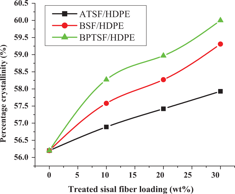
Percentage crystallinity as obtained from DSC measurements for untreated and treated microsisal fibers (a) ATSF/HDPE, (b) BSF/HDPE, and (c) BPTSF/HDPE, microcomposites containing different weight percentage of treated microfibers. DSC: differential scanning calorimetric; ATSF: alkali-treated sisal microfiber; HDPF: high-density polyethylene; BPTSF: benzoyl peroxide–treated sisal fiber; BSF: benzoylated sisal microfiber.
Electrical properties of HDPE/sisal fiber microcomposite
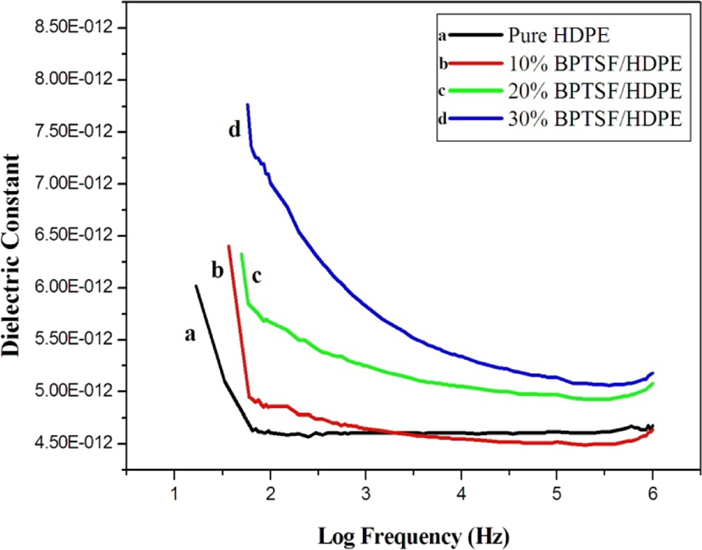
The dielectric constant of a material depends upon the polarizability of the material. If there is greater polarizability of molecules, dielectric constant will be high. The dielectric constant of polymeric materials depends on interfacial, dipole, electronic, and atomic polarization. Figures 9, 10, and 11 show the variation of dielectric constant ε′ with frequency at room temperatures. It is evident from these figures that ε′ decreases with increasing frequency at fixed temperature which is the expected behavior in most dielectric materials. This is due to the dielectric relaxation which is the cause of anomalous dispersion.
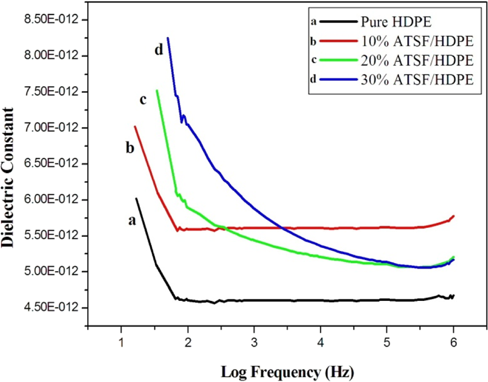
Ambient dielectric constant versus logarithm of frequency for ATSF/HDPE microcomposites with different microfiber loading. ATSF: alkali-treated sisal microfiber; HDPF: high-density polyethylene;
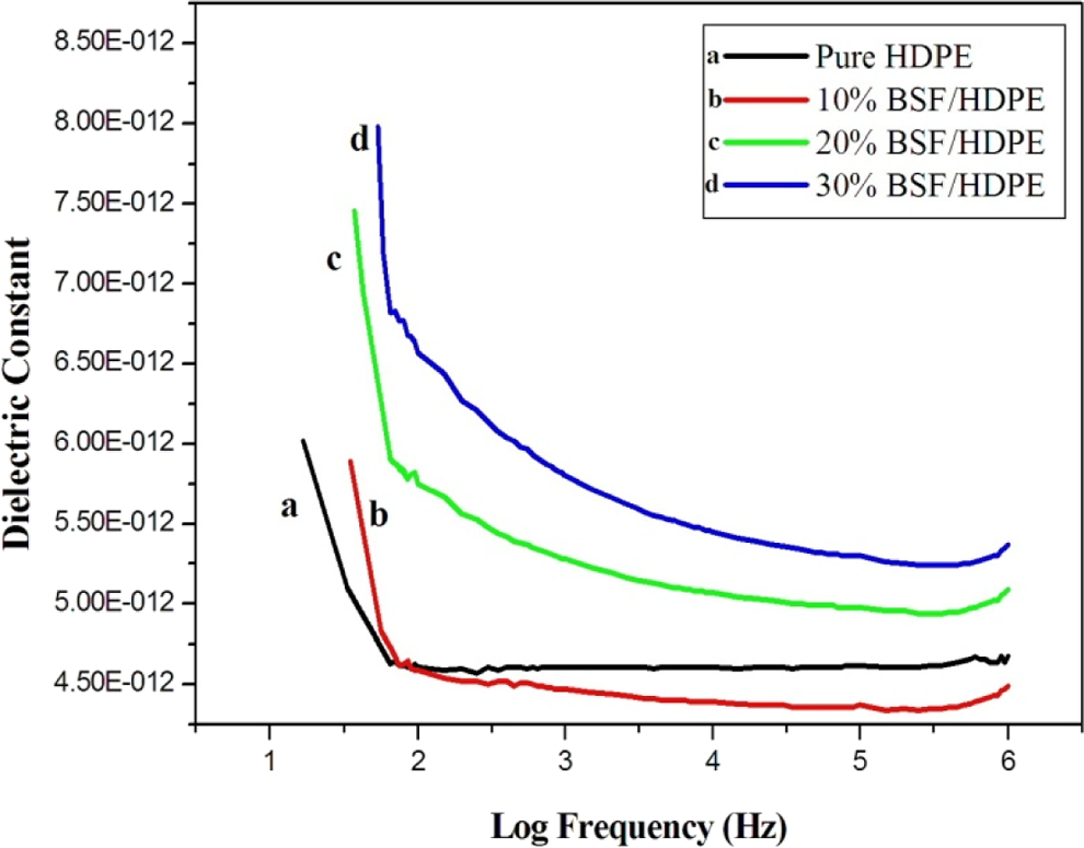
Ambient dielectric constant versus logarithm of frequency for BSF/HDPE microcomposites with different microfiber loading. HDPF: high-density polyethylene; BSF: benzoylated sisal microfiber.
Ambient dielectric constant versus logarithm of frequency for BPTSF/HDPE microcomposites with different microfiber loading. HDPF: high-density polyethylene; BPTSF: benzoyl peroxide–treated sisal fiber.
Figure 9 shows that the dielectric constant of alkali-treated sisal/HDPE microcomposites is higher than the dielectric constant for the pure HDPE at all frequencies. This may be attributed to the increase of crystallinity of the composite material as a consequence of alkali treatment which will result in a reduction in the capacity of the fibers to adsorb moisture. The moisture content will therefore decrease as a result of treatment by NaOH. Hence, the component of the orientation polarization which is due to the presence of polar water molecules decreases. Accordingly, the dielectric constants of alkali-treated sisal/HDPE microcomposites were higher than those of the pure HDPE at all frequencies. 18
In case of benzoyl chloride treatment, the presence of water and impurities in the fiber decrease, and the dielectric constant of BSF/HDPE microcomposites decreases due to the decrease of water content. As compared with neat HDPE, the BSF microcomposites show higher dielectric constants as shown in Figure 10.
As a result of peroxide treatment, the hydrophilicity of the fibers decreased, and this is consequently accompanied by a decrease of polar water molecules in the microfiber. Therefore, the orientation polarization decreases considerably, and hence, the dielectric constant also decreases. As compared with the neat HDPE, the BPTSF microcomposites show higher dielectric constants as shown in Figure 11. 18
Figures 9, 10, and 11 prove that better dielectric constant can be obtained using different types of chemical treatment of sisal fibers discussed above. The decrease in dielectric constant with increased frequency is attributed to orientation polarization of molecular species. 18
Morphology of treated HDPE/sisal fiber microcomposites
The micrographs of the fracture surface of the microcomposites containing 10, 20, and 30% of treated sisal microfibers were studied using SEM. The morphology of the fracture surface reflects the reasons why the mechanical properties of the microcomposites under different conditions are superior to those of the neat polymer. Figure 12 shows the SEM of neat HDPE and treated sisal fiber/HDPE microcomposites. It can be observed from the figure that there is excellent adhesion between the matrix and the mercerized microfiber. There are no signs of voids between the polymer and the treated sisal microfibers. The good compatibility between the treated microfiber surface and the polymer is reflected also on the good orientation of the fiber in the direction of the molding (perpendicular to the fracture surface). This also improves the mechanical properties of the resulting composite material as discussed earlier.
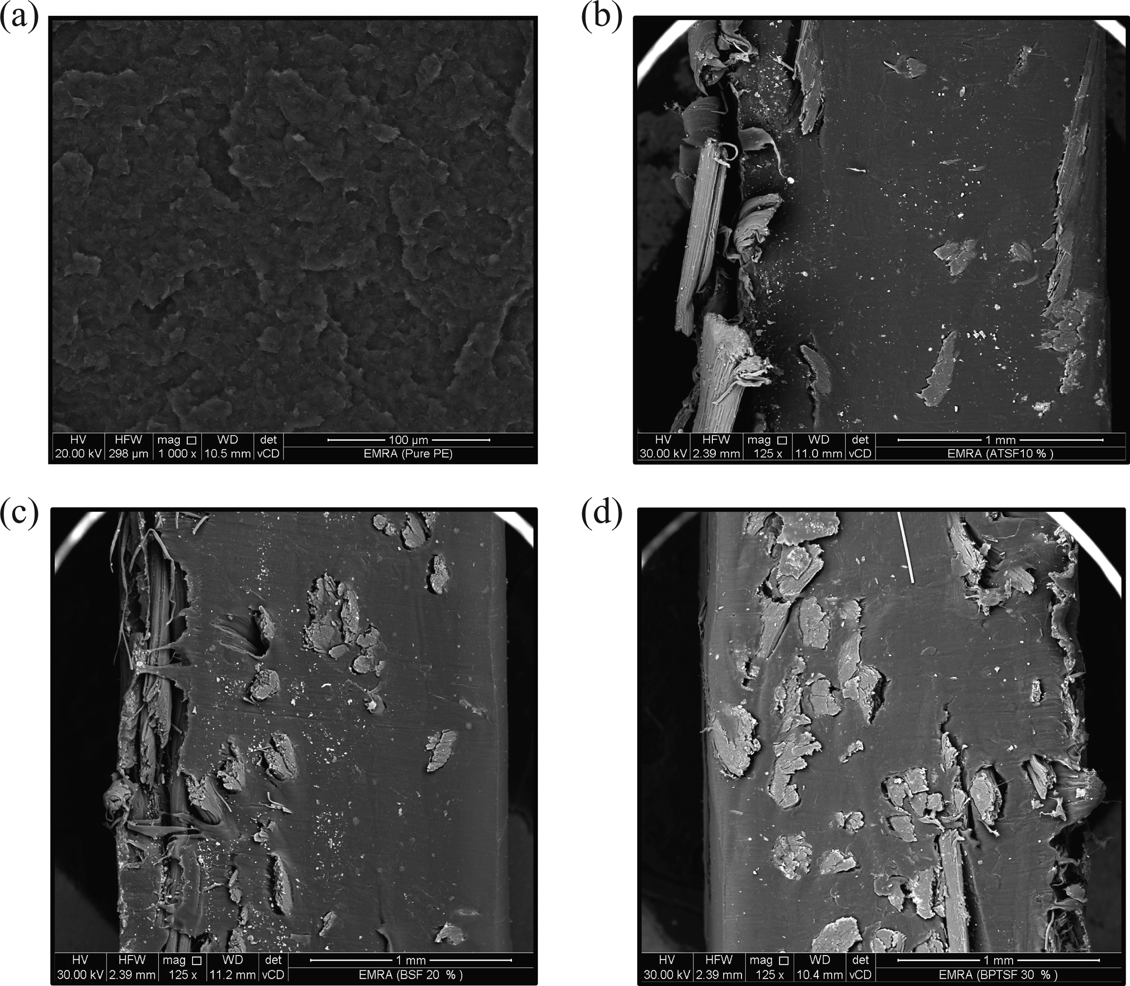
SEM micrographs of (a) pure HDPE, (b) 10% ATSF/HDPE, (c) 20% BSF/HDPE, and (d) 30% BPTSF/HDPE composites. BSF: benzoylated sisal microfiber; HDPF: high-density polyethylene; BPTSF: benzoyl peroxide–treated sisal fiber; ATSF: alkali-treated sisal microfiber; SEM: scanning electron microscope.
Conclusions
Recently, we published a couple of articles 27,28 on improving the ultraviolet absorption properties of HDPE using zinc oxide nanoparticles in order to facilitate the usage of those polymers in food packaging and sun block windows. The use of sisal fibers to reinforce HDPE has also attracted lots of interest in recent years to improve mechanical and dielectric properties. 29,30 In this article, we demonstrate that chemically modified sisal microfibers can effectively be used in the reinforcement of HDPE in order to improve the physical and mechanical properties of the resulting microcomposite. Three possible ways for the fiber surface modification have been suggested including alkali treatment, benzoyl chloride treatment, and benzoyl peroxide treatment. All chemical modifications were found to increase the compatibility between the hydrophilic fiber surface and the hydrophobic polymer matrix. The resulting microcomposite can find its way in electrical appliances and in the car industry replacing metallic parts especially those requiring high dielectric constant and superior mechanical properties.
Footnotes
Declaration of Conflicting Interests
The author(s) declared no potential conflicts of interest with respect to the research, authorship, and/or publication of this article.
Funding
The author(s) received no financial support for the research, authorship, and/or publication of this article.