
Abstract
In addition to fiber properties, the fabric structure plays an important role in determining ballistic performance of composite body armor textile. Textile structures used in ballistic protection are woven fabrics, unidirectional (UD) fabric structures, and nonwoven fabrics. In this article, an analytical model based on wave propagation and energy balance between the projectile and the target is developed to analyze hybrid fabric panels for ballistic protection. The hybrid panel consists of two types of structure: woven fabrics as the front layers and UD material as the rear layers. The model considers different cross sections of surface of the target in the woven and UD fabric of the hybrid panel. Also the model takes into account possible shear failure by using shear strength together with maximum tensile strain as the failure criteria. Reflections of deformation waves at interface between the layers and also the crimp of the yarn are modeled in the woven part of the hybrid panel. The results show greater efficiency of woven fibers in front layers (more shear resistance) and UD yarns in the rear layers (more tensile resistance), leading to better ballistic performance. Also modeling the yarn crimp results in more trauma at the backface of the panel producing data closer to the experimental results. It was found that there is an optimum ratio of woven to UD materials in the hybrid ballistic panel.
Introduction
Nowadays, hybrid panels with high-strength yarns such as ultrahigh-molecular-weight polyethylenes are widely used for the ballistic protection because of their lightweight and high performance against impact. 1 There are two basic types of materials used in soft armor construction: aramid (woven) and high-performance polyethylene unidirectional (UD) fibers. Investigation on the ballistic protection is focusing more on the development of a hybrid design and its architecture (a combination of woven and UD layup). In woven fabrics, crimp is formed due to the interlacing of warp and weft yarns. The impact affects the yarn by applying a tension to the yarn through its axes. When a projectile impacts a fabric plane, it deflects toward the backface of the panel. This causes the yarns to move toward the back of the fabric panel more and creates a deeper trauma. In fact, due to the crossover points in woven composites, a greater extension of the ballistic wave is reflected back, rendering the ballistic impact to a smaller composite area and reducing the rate at which energy can be dissipated. To improve this shortcoming, a non-crimp fabric is made using UD plies in the warp and weft direction. Thus, the stress wave propagated on the fabric plane is more than being transmitted to the back of the fabric layers. This forms a smaller depth of the backface and the damage size. Park et al. 2 found that by combining or hybridizing UD/woven fabrics, the materials lead to a better ballistic performance, especially by increasing the energy-absorption capability. In woven fabric construction, weft yarns will break before warp yarns during ballistic impact event. 3 Hence, a basic fundamental study is required for each individual architecture before employing them in hybrid model. One important step to design the hybrid panels is the combination of woven fabrics layers with UD fiber-reinforced layers.
In woven fabrics, due to the existence of intersection point among the fibers, filaments are not stretched along their axis until the yarns are fully uncrimped. This decreases the velocity of the longitudinal strain wave and affects how the yarn performance is exhibited. In fact, because of the existence of non-crimped yarn, the longitudinal strain wave travels faster in UD fabrics than in woven fabrics. This leads to the participation of more fabric material in energy absorption process. Hybrid panels formed by both UD fabrics and woven fabrics show better performance than single material panels. Experimental investigation carried out by Thomas 3 showed that single material aramid panels made more depth of backface signature than hybrid panels, and thus these panels demonstrate a higher ballistic resistance than single UD material or woven fabric panels. Karahan 4 found that about 13.9% less energy was transmitted to the backing material in a hybrid panel than in a single UD material panel.
The penetration and perforation of composite targets by projectiles involve complex processes that have been studied analytically during the last few decades. 5,6 Many parameters affect the ballistic performance of hybrid composite targets such as materials, structures of composite, dimensions, boundary conditions, and so on. 7 –9 Smith et al. 10 studied the behavior of an infinite long yarn under transverse impact. They showed that the impact creates longitudinal and transversal waves on a single yarn which propagates down the yarn. The shape of the transverse wave is like an inverted V shape.
Haque and Gillespie 11 developed a new penetration equation base on new definition of the projectile instantaneous velocity for ballistic limit analysis. With this new definition, the new penetration equation is derived, satisfying both the conservation of momentum and the energy principles simultaneously.
Roylance 12 studied the effects of yarn linear viscoelasticity using a finite-element simulation and obtained many behavioral features seen in experiments. Naik et al. 13 presented an analytical model to predict ballistic limit velocity, residual velocity, and the energy absorption of two-dimensional (2-D) woven fabric composites. This model is based on wave theory, dynamic mechanical properties, and fracture properties of the textile composite.
Mamivand and Liaghat 14 developed an analytical model of 2-D woven fabric based on momentum and wave theory. The model allowed variation of distance between layers in order to study its effect on the ballistic resistance of the composite target.
Ha-Minh et al. 15 developed an analytical model based on both energy conservation and strain wave theory for 2-D plain weave fabrics subjected to ballistic impact. Reflections of strain waves are considered in this model. The effects of the dimensions of the panel and the distance between layers on its ballistic performance are also studied.
Mohan and Velu 16 developed a modified analytical model, based on the model proposed by Naik et al. 13 , to predict the impact behavior of UD cross ply laminates. This model can predict the energy absorbed by different damage and energy-absorbing mechanisms. Chen et al. 17 studied the behavior of hybrid fabric panels subjected to transverse impact. The finite element method was used to predict the response of different layers of a hybrid fabric model upon impact. Chen et al. 18 also developed a modified analytical model based on the momentum theory, taking into account the strain gradient between the panel layers and its effects on the tensile strain at the edge of the projectile.
Most of the studies presented earlier developed an analytical model for woven fabric panels. So an attempt is made to develop an analytical model to predict the impact behavior of hybrid panel. This article presents an analytical model based on wave propagation and energy balance to analyze hybrid fabric panels for ballistic protection. The architecture of this hybrid panel consists of two types of structure: woven fabrics as the front layers and UD fabrics as the rear layers. The UD fabric used in this investigation are laminated at 0° and 90° alternately.
Analytical model
During impact, behavior of the unidirectional/woven hybrid panel is different in woven fabric and UD part. At woven fabric, after the impact of projectile to the hybrid panel, stress wave propagation and properties are the same in weft and warp directions, while in the UD part of the hybrid panel, properties along the yarn and in the direction normal to the yarns are different. In this section, an analytical model is developed to predict the evolution of projectile velocity, the deformation, and absorption energies of these two parts (woven and UD fabric) of a hybrid panel during impact. This analytical model takes into account possible shear failure by using shear strength together with maximum tensile strain as the failure criteria. The crimp of the yarn in the woven part of the hybrid panel and also reflections of deformation waves at interface between the layers are modeled. This model is based on the principle of energy conservation. As assumed by Ha-Minh et al., 15 during the impact event, the projectile is perfectly rigid, strain of secondary yarns is distributed linearly from the edge of the primary yarns to the transverse strain front, and all primary yarns in a layer have the same deformation at any time. With these assumptions, three main mechanisms of energy absorption are considered in this analytical model: kinetic energy of the formed pyramid, failure and deformation of primary yarns, and deformation of secondary yarns. Figure 1 shows the primary and secondary yarns in a hybrid panel.
Primary and secondary yarns in unidirectional (left) and woven fabric (right).
In this model, analysis is based on layer by layer system. This means that with considering a time interval (Δt), depth of penetration of projectile is calculated depending on whether the next layer will be activated or not. If the next layer has been activated, all parameters such as velocity of projectile, mass of pyramid, amount of absorbed strain energy, and kinetic energy can be calculated.
Absorbed energies
According to Smith et al., 10 when the projectile is in contact with the yarn, ahead of the elastic wave front, the strain is zero and behind it, the strain is constant and can be calculated using the following equation:

where c = E/ρ is the velocity of the longitudinal wave, E is the yarn Young’s modulus, and ρ is the yarn density. As the projectile impacts onto the woven fabric composite, a wave of deformation (ε0) starts to propagate on primary yarns. Because of interlacing of warp and weft yarn, this wave reaches the intersection point and reflected there (Figure 2). With these assumptions, the critical time (tcritical) can be introduced as follows:
Local growth of the strain at the impact point due to waves reflections. 15
where d is the distance between adjacent yarns, c = E/ρ is the velocity of longitudinal strain wave on a yarn. When the strain wave ε0 reaches the intersection point (two different materials), transmission strain wave (εt) and reflection strain wave (εr) are created, which can be determined by the following equations:

where R1 and R2 are acoustic impedances. It can be noted that the mass density of yarns is doubled at the intersection points.
16
So, if the acoustic impedance of yarn,
In other words, the reflection coefficient is not doubled at the impact point:
The local strain at the point of impact (εmax) is sharply increased at tcritical after impact and can be determined using the following equation:

where ε0 is the deformation of primary yarns immediately after impact, kε is the coefficient to take into account the interference of strain waves. This coefficient can be taken equal to 2.0 for woven fabric 12 and 1.0 for UD layers.
The energy and momentum conservation law can be used during impact. In the time interval Δt, the equation of energy conservation can be written as follows:

where Mc(t) and v(t) are the mass of the fabric cone and the velocity of the projectile respectively and DE(t) is the variation of deformation energy during a time interval. The mass of the formed pyramid of the layer j at the instant t can be calculated as follows:
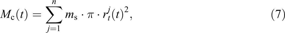
where

where

The strain energy of primary yarns of the layer j at the instant t can be determined by the following relationship:

where:

and
Deformation energy of secondary yarns in woven fabric
It can be noted that the deformation zone of secondary yarns on the layer j limits between two radii:
Modeling of deformation of secondary yarns in woven (left) and unidirectional (right) fabric.

Therefore,

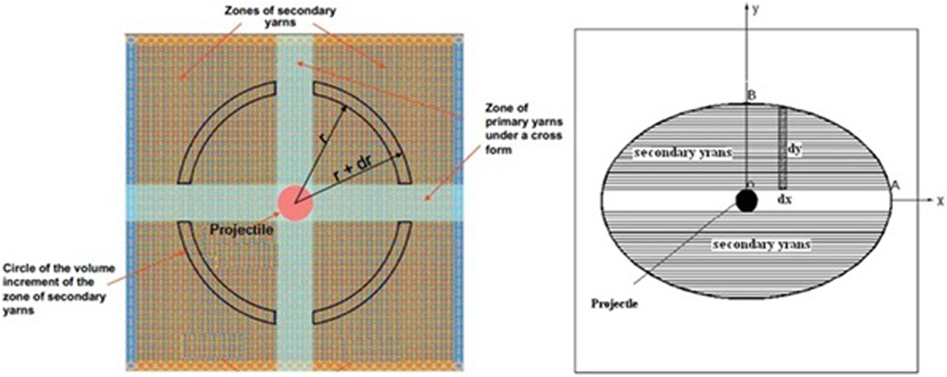
Deformation energy of secondary yarns in UD fabric
An elliptical cone is formed on the backface of the panel during impact. Due to orthotropic nature of the UD fabric, the shape of the wave front would be elliptical. The surface area of the elliptical cone can be determined based on transverse wave propagation. During impact event, the transverse wave moves from xt1 to xt2 in x direction and from yt1 to yt2 in y direction. The distance xt2 and yt2 are determined based on additional transverse wave propagation which has been taken place during that time step.
As mentioned before, because of the orthotropic nature of the panel the strain variation is different in directions x and y. As shown in Figure 3, the strain variation is assumed to be linear in both directions OA and OB. The strain at the boundary of cone is assumed to be zero to simplify the model. Based on the assumption, boundary conditions can be presented by the following equations:
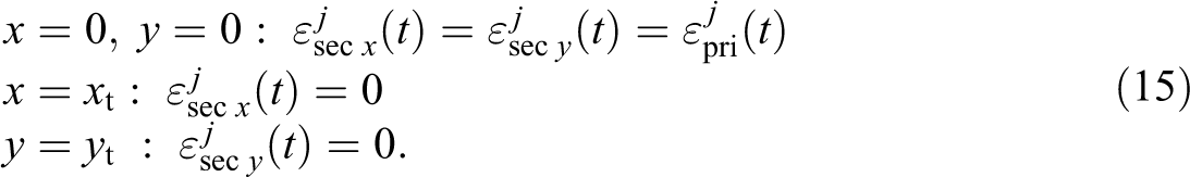
From these boundary conditions, the strain can be formulated in x and y directions as:

and

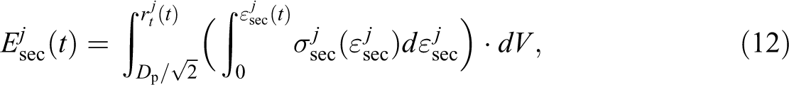
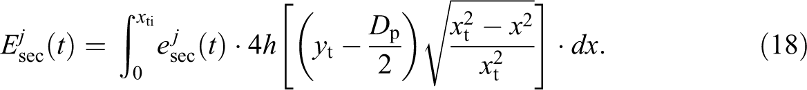
The energy absorbed by deformation of secondary yarns can be obtained by:
The variation in the strain energy of yarns in the time interval Δt can be formulated by the following equation:

where Edef(t) and Edef(t−Δt) are strain energies of yarns at the instant t and (t−Δt). Yarns strain energy Edef(t) is the sum of the strain energy of primary yarns and strain energy of secondary yarns. The total strain energy of n layers for primary and secondary yarns is calculated using the following equation:

Failure criteria
In the analytical model presented here, possible shear failure is considered using shear strength together with the maximum tensile strain as the failure criteria. Lim et al. 19 found that aramid fibers fibrillate under high strain rate compression, and this means that the main failure mechanism of the transversely impacted fiber was related to fibrillation. Chen et al. 17 showed in their experiments that the failure tensile strength is low for the front layers and it turns to be higher for the rear fabric layers, and the failure shear strength for the front layers is high and it becomes lower for the rear fabric layers. This means that the main reason for the failure of fabric layers at the front of the panel is due to shear stresses.
Cheng et al. 20 also investigated that the main reason for the failure of aramid fiber was fibrillation. It is assumed that fibrillation of fibers is regarded as fiber failure in this analytical model. Thus, two failure criteria were applied for the model in the study. On the other hand:

where εmax is tensile strain failure of fiber,
Modeling of crimp in the woven fabric part
In woven fabrics, crimps are formed because of the interlacing in warp and weft yarns. Crimp of fiber yarns decreases the in-plane properties leading in serious failures such as fiber kinking that affects the ballistic performance of panel. Because the velocity of strain wave is different in uncrimping stage, it is necessary to calculate the strain at this stage. To do this, the yarn pullout test and the affecting parameters on this phenomenon need to be studied. Yarn pullout can be an important mechanism of energy absorption during the ballistic impact. 21 In the yarn pullout test, one or two lateral edges will be fixed and one or more threads are pulled out. On this basis, variation of pullout force versus displacement can be plotted. As shown in Figure 4, “uncrimping” stage is the beginning of the force–displacement curve and “yarn translation”, corresponding to the portion past the peak load point. The uncrimping process is irreversible, meaning that the yarn will not return to the original crimped configuration. The yarn uncrimping and yarn translation process dissipate some energy defined as the area under the force–displacement curve.
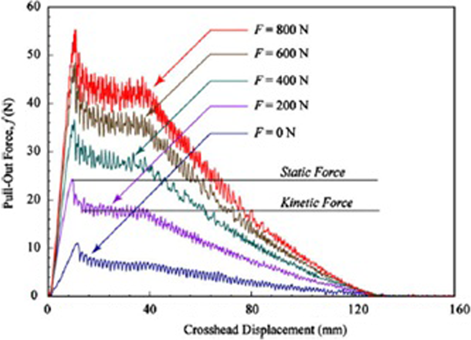
Yarn pullout force versus crosshead displacement for varying magnitudes of the applied preload. 22
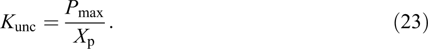
Pmax is the maximum force required to pullout the yarn and Xp is the displacement at the maximum force that depend on various parameters and that increases linearly with increasing yarn length. As the number of neighboring yarns pulled during a test increases, the peak load and displacement at peak load point increase too. Kirkwood et al. 23 presented the following equation for pulling out n yarn simultaneously:

If Kunc is the stiffness of a yarn during uncrimping phenomena 24 , then:
Now with assumption of linear relation between stress–strain, it can be concluded using the following equation:
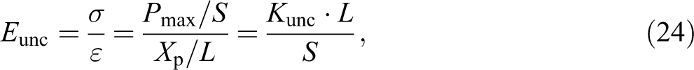
where Eunc is the yarn longitudinal Young’s modulus during uncrimping stage, S is yarn cross-section area, and L is length of the yarn.
Now the velocity of strain wave created in the yarn during uncrimping after impact can be determined using the following equation:
Therefore, Cunc can be used instead of C to calculate the velocity of the transverse wave. In the analytical model developed by Ha-Minh et al., 15 the following equation is used to calculate the velocity of transverse wave during impact:
It is noted that the coefficient ku, which takes into account the effect of the weaving (such as crimping) on the velocity of the transverse wave can vary as a function of time. Therefore, combination of equations (25) and (26) result in the following relation:

Thus:
Investigations show that the lateral force (preload) in the pullout test affects pullout force. Kirkwood et al. 23 reported by increasing the transverse fabric tension, the yarn pullout energy increases. In fact, increasing the tension on the transverse yarns increases normal forces between yarns, resulting in more frictional resistance to yarn pullout and also a more tortuous path during yarn translation in the pullout phenomena.
In force–displacement curve (Figure 4), the displacement at peak load is approximately independent of transverse tension since the length scale of the pullout curve is primarily determined by the length of the fabric specimen. Rao et al. 22 also investigated that linear relationship could be employed to predict the pullout force in terms of the applied preload. The linear relationship equation can be written as:

where Pmax is the average yarn pullout force, Fpreload indicates the applied preload, and m1 and m2 are the constant coefficient of the linear relationship. According to equations (14) to (17), it can be concluded that coefficient ku is a function of Fpreload and Kunc. In other words:

Results and discussion
As discussed previously, three mechanisms of energy absorption are considered in our model, that is, kinetic energy of pyramid forming, deformation of primary yarn, and deformation and strain energy of secondary yarn. These energy absorption mechanisms are applied on woven fabric and UD plies of hybrid panel.
According to the equations provided in this article, all parameters of penetration process such as absorbed energies, velocity of projectile, and height and width of the pyramid on the backface of the panel at each time interval can be calculated. It is vital to emphasize that all parameters at any time (t) can be determined from the projectile velocity at the time (t−Δt). Thus, the time interval must be chosen small enough to obtain accurate results, but too small time step will increase the computational time. Therefore, there is an optimum time step for any impact velocity. The MATLAB software is used to calculate the parameters and to obtain the results.
The material used in woven section is a Style 745S plain-weave fabric of 30.5 × 30.5 cm2. Material properties were taken from the work by Liaghat et al. 8 The area density of a single layer is 448 g/m2. The thickness of a single layer is 0.05 cm. The whole target is 10 layers, and a space of 0.05 mm is left between the layers. For the fabric, longitudinal elastic modulus is 96 GPa, and a failure strain of approximately 3% is considered. The material used in UD part is fabric made of Dyneema SB21 with areal density of 145 g/m2. The projectile used in this model is fragment-simulating projectile (FSP) type with mass of 2.82 g and diameter of 7.62 mm. Initially, the panel with 100% woven fabric structure is analyzed, and the results are compared with hybrid panel that consist of woven and UD fabric.
Woven fabric
Absorbed energy by these three mechanisms is compared in Figure 5. As shown in this figure, the penetration of the projectile can be divided into three main phases. For an impact velocity of 375 m/s in the first phase (t < 150 µs), the kinetic energy of the pyramid and the deformation energy of the primary yarns contribute primarily to deceleration of the projectile. In phase 2 (150 < t < 600 µs), the development of the pyramid deformation is the main mechanism for the energy absorption. In the last section (t > 600 µs), the deformation energy of yarns is the main mechanism of energy dissipation. At the time t = 500 µs, dimensions of the pyramid has reached the edge of the panel. Therefore, the kinetic energy of this pyramid decreases with the projectile velocity. On the other hand, the deformation energies of primary and secondary yarns are rising sharply. It can be noted that because of more secondary yarns than the primary ones, the secondary yarns contribute largely to the deformation energy of the fabric. As mentioned before, the crimp of the yarn in the woven fabric is modeled in this study. Figure 6 shows energy absorption by pyramid forming of the panel in two cases: no crimp in fabric and crimp yarns with Kunc = 5000 N/m. 25 As shown in Figure 6, the energy absorbed by pyramid forming of the panel with no crimp is more than the case with Kunc = 5000 N/m.
Comparison of absorbed energy in primary and secondary yarns and pyramid formed during impact.
Comparison of absorbed energy in pyramid forming in the new model and Minh. 15
Figure 7 shows depth of backface signature in two cases: no crimp in fabric and crimp yarns with Kunc = 5000 N/m. As shown in Figure 7, the backface of the panel in case of Kunc = 5000 N/m is more than the case with no crimp, which is closer to the experimental result. In fact, in the case of woven fabric, as the yarns are interlaced together, the fabric structure permits relative movement of the yarns in the fabric. When struck by a projectile, primary yarns are stretched and pulled out. It is evident that the limitation of fiber movement in the UD fabrics leads to smaller depth of backface than the woven fabric. Therefore, majority of the impact stress is propagated on the fabric plane and less is transmitted to the back of the fabric layers. This forms a smaller height of pyramid.
Effect of crimp on the depth of backface of the panel in two cases, no crimp and crimp with stiffness Kunc = 5000 N/m.
On the other hand, it is evident that the in-plane fiber continuity and linearity of UD make the stress waves produced by high-velocity projectiles propagating rapidly and effectively. As compared to UD, the existence of interlacing points between yarns in woven fabric restricts the projectile energy to be dissipated over a shorter time.
Hybrid panel
Experimental tests 17 showed that placing the woven fabric at the front face of the impact gave better ballistic protection for the panel than the reverse sequence. Therefore, the hybrid panel considered to analyze in this study consists of woven fabrics as the front layers and UD material as the rear layers. The UD fabrics used in this investigation are laminated at 0° and 90° alternately. On this basis, five combination of panel were designed. In order to better compare the panel performance, areal densities of different panels were considered as similar as possible. The sequence of panel is given in Table 1.
Architecture of panels.
Results of this analytical model including depth and width of backface of pyramid of the panel and ballistic limit are presented in Table 2 at impact velocity of 375 m/s.
Comparison of height and width of the backface pyramid for layup shown in Table 1.
z: height of pyramid; r: width of pyramid.
For example, two combinations of hybrid panel, A (100% woven fabric) and E (100% UD) given in Table 2, can be compared. It is found that in case A, the depth of backface (height of pyramid) is 30% more than in the case E. Also width of the formed pyramid at the backface in case A is about 19% less than in the case E. In fact, the width of the formed pyramid resulted in distribution of strain energy basis on moving ahead of transverse strain wave. As shown in Table 2, the ballistic limits of the panel in case A is lower than in case E.
Figures 8 and 9 show the variation of the height and the width of the formed pyramid during the penetration process in the pure woven fabric panel (combination A) and pure UD panel (combination E). The width of transverse deflection is found to be higher in the UD panel than in the woven fabric panel as shown in Figure 9. This demonstrates a larger surface area of UD plies contributed to the energy dissipation and thus leads to higher ballistic performance in the pure UD panel than in the pure woven panel.
Variation of width of the formed pyramid during the penetration process in pure woven and pure unidirectional panels (combinations A and E).
Variation of height of the formed pyramid during the penetration process in pure woven and pure unidirectional panels (combination A and E).
It can be seen from Table 2 that combination D, which consists of 2 layers of woven fabric and 15 layers of UD layers, exhibits the lowest value of the height of the pyramid that indicates its higher performance over other panels. It is found that, beyond this proportion, an increase in the proportion of woven fabrics in the panel leads to an increase in backface signature value. The combination A, which consists of 10 layers of woven fabric, gives the worst performance.
For validation of the analytical model, experimental results by Chen et al. 17 have been used. Hybrid fabric samples used in this section contain a plain woven fabric made of Dyneema®_SK75 and a UD fabric made of Dyneema_SB21with areal density of a single layer 240 and 145 g/m2, respectively. Properties of the two fabrics are given in Chen et al. 17 . In this arrangement, the projectile is a 1 g, cylindrical projectile whose length and diameter both measure 5.5 mm. The average of the velocity of the projectile is about 450 m/s. Five configurations were designed as shown in Table 3. In order to better compare the panel performance, the areal densities of different panels were kept as similar as possible.
Type of panels.
In Figure 10, the depth of backface signature of the panel predicted by the analytical model is compared with the experimental results by Chen et al. 17 . As shown in Figure 10, the combination of 6 layers of woven fabric and 30 layers of UD fabric shows the lowest value, which indicates its superior performance over other panels. Also this figure shows that results of the analytical model have acceptance consistency with experimental data. In this case, the crimp of the woven part of the hybrid panel has not been considered.
Comparison of depth of the backface signature for five configurations of the panel.
In Figure 11, the depth of the backface of the panel compared with the experimental results by Chen et al. 17 . In this configuration, the crimp of the woven part of the panel have been considered with Kunc = 5000 N/m. 25 As shown in Figure 11, results of the analytical model are closer to the experimental data than before configuration as shown in Figure 10. In fact the depth of the backface increases because of the existence of crimp in the woven part of the panel as mentioned before.
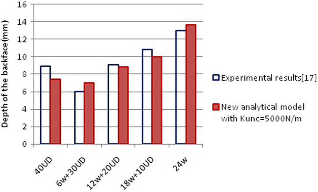
Comparison of depth of the backface signature for five configurations of the panel with considering Kunc = 5000 N/m.
Conclusion
A modified analytical model has been developed for hybrid woven/UD panel subjected to ballistic impact. In this model, a hybrid panel consisting of woven fabric as front layer and UD plies as back layers were analyzed. Crimp phenomena and reflection of transverse wave of intersection point in the fabric are considered in the model. Results show that the ballistic resistance of the hybrid woven/UD panel is higher than panel with single material (woven fabric or UD material). Also height of the pyramid of the backface signature in hybrid panel is less than pure woven fabrics panel with the same areal density. There is an optimum ratio of woven to UD materials in the hybrid ballistic panel depending on the material properties.
Footnotes
Declaration of Conflicting Interests
The author(s) declared no potential conflicts of interest with respect to the research, authorship, and/or publication of this article.
Funding
The author(s) received no financial support for the research, authorship, and/or publication of this article.