
Abstract
The end of life of carbon fibre-reinforced polymer (CFRP) structures represents a major challenge to the aerospace industry, as new European regulations are demanding recycling solutions that can be complicated and expensive to apply. This study aims to address new practical ways to recycle CFRP materials. CFRP materials with a polyether ether ketone (PEEK) matrix were fragmented via electrodynamical fragmentation, which exhibits several benefits compared to mechanical shredding processes, especially for composites commonly found in the aerospace industry. The fragments are characterized and reused to produce new CFRP aerospace parts. Structural testing of recycled composite parts revealed a 17% decrease of the mechanical properties compared to the novel material. The combination of these manufacturing and recycling techniques closes the cradle to cradle loop of thermoplastic CFRP.
Keywords
Introduction
In the 70s, the demand from national airlines for transatlantic and other intercontinental civil flights pushed the aircraft manufacturers to start the development and the production of long-range wide-body airliners (Boeing 747 and Airbus A300). In the 80s, technological improvements in the aerospace industry and low kerosene prices amplified the demand for intra-continental flights and led to new generations of single aisle short-range commuters such as the Boeing 737 and Airbus A320 family that met a great success with a respective number of 7700 and 5900 airplanes produced over the last 30 years. 1,2 Whilst the usual lifetime of civil aircraft is between 20 and 30 years, this lifetime is limited not only by the technical factors such as the aircraft structural mechanical fatigue but also by the economic factors. The economic value of an aircraft is reduced during its use until a certain point when the operating costs such as fuel consumption, maintenance, repair or upgrading become more expensive than buying a new aircraft. 3 Fuel consumption has become the most critical factor in an aircraft’s lifetime, where kerosene prices have seen an increase of 645% over the last 20 years. 4 As a result, more airliners are pushed to earlier end of life (EoL). 5
During the past decades, the ultimate solution for the EoL of aircraft consisted mainly in collecting the most valuable items to be re-certified and sold in the spare parts market, such as landing gears, jet engines or avionic systems. The rest, mainly the fuselage, wings and interiors, were grinded out and landfilled or stored in large graveyards, which are getting full with currently over 2000 commercial airliners stored worldwide. More than twice this number of stored airplanes are expected to be withdrawn or retired from service over the next 20 years. 5 This problem of increased waste disposal has pushed regulatory organizations to provide a framework to EoL regulations such as the ‘waste framework’ European directives. 6 Even more specific directives such as the end of life of vehicles (ELVs) directive 7 states that new vehicles should be recyclable with recovery rates up to 85% and 95% by 2006 and 2015, respectively. This ELVs directive may also apply to commercial aircraft in the future 3 and pushes manufacturers to develop more ecologically friendly solutions to dismantle and recycle their aircraft. Aircraft manufacturers are developing these technologies in large demonstration projects such as the Process for Advanced Management of End of-Life Aircraft project initiated by Airbus aiming at dismantling an entire Airbus A300-B4. Every part in this aircraft can be listed for recovering, recycling or reuse. The main challenge of this project was to avoid creating waste by reaching a maximum rate of recovery and recycling. The global recyclability of this airplane was increased from 50–60 wt% to 85 wt% (Figure 1). Material recycling represented over 55 wt% of the total weight of the aircraft. As a result of the project, the amount of landfilled waste was reduced from 50 wt% to 15 wt%. 9 Composite materials represented only 4 wt% compared to 77 wt% of aluminium material in this 30-year-old airplane.
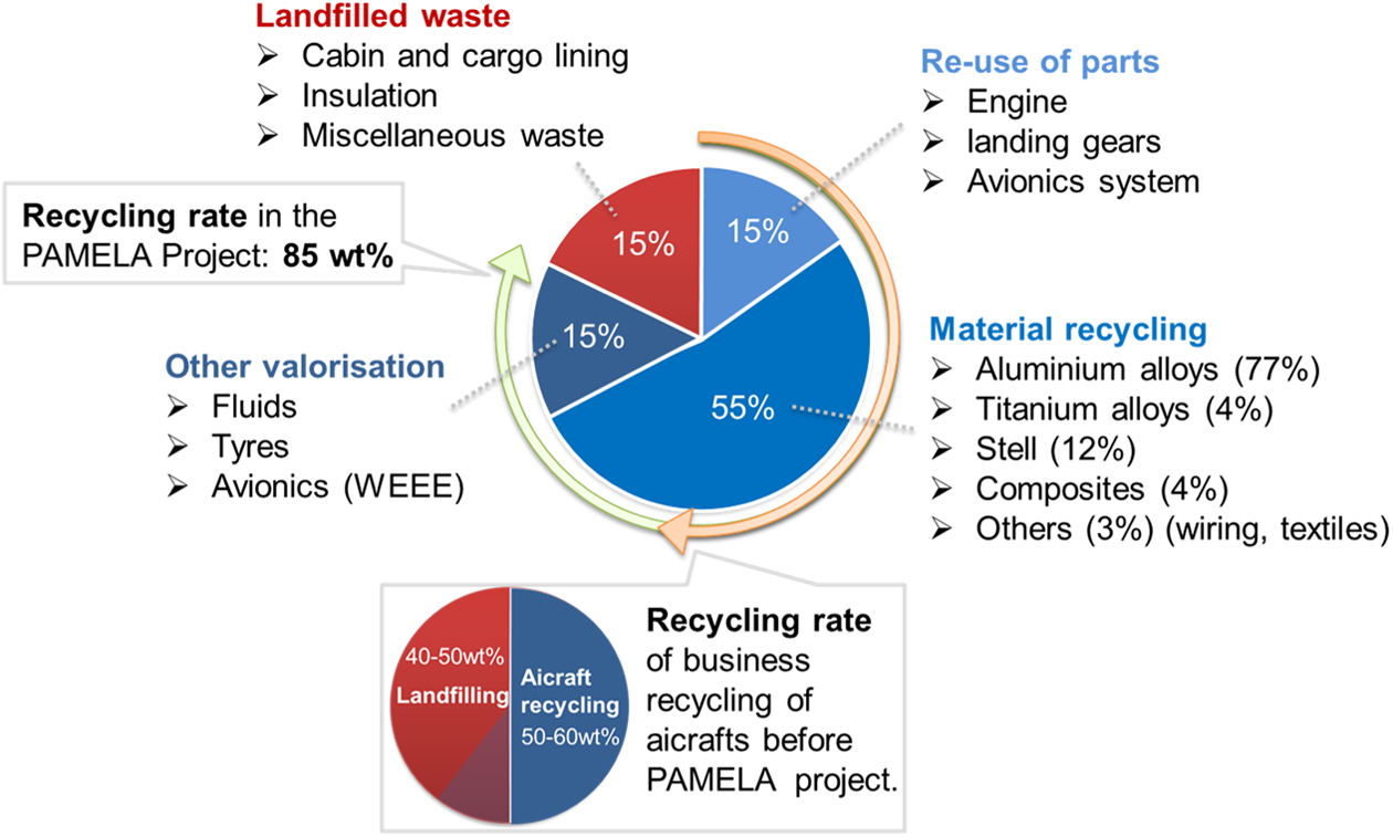
Chart summarizing the main results achieved in the PAMELA-LIFE project, recycling of an Airbus A300-B4 in wt% (data from Airbus 8 ).
Carbon fibre-reinforced plastic (CFRP) materials are good candidates for replacing metallic components due to their very attractive mechanical properties such as high strength and high rigidity, and their low density and absence of corrosion compared to metal-based materials are major assets. 10
For these reasons, a greater amount of CFRP has been implemented by aircraft manufacturers reaching 53 wt% in the last aircraft generations 11 in order to further reduce weight and fuel consumption. 4 CFRP materials with a thermoset matrix such as epoxy resin have been well integrated in the aerospace industry since 1983 with vertical fins of Airbus A300-600/A310 12 ; however, the recycling of these parts remains challenging. In the past, ultimate solutions for CFRP materials were the landfilling or incineration. 13 As an alternative to ultimate landfilling, two main industrial recycling routes exist: the matrix and the fibres can be roughly ground through a mechanical shredding process to be reused as filler in cement, 14 inducing an extreme uneconomic down cycling limiting the interest of the recycling industry. The other route is the recovery of the costly carbon fibres 15 by removing the thermoset matrix using thermal pyrolysis, which consequently induces a poor CFRP recovery rate about 50 vol%. Furthermore, the resulting recycled carbon fibres are usually short in length with reduced quality and mechanical properties that critically limit their applications and reduce once again their economic value 16 and the interest of the recycling industry. Upcoming methods such as the fluidized bed process, critical water oxidation 17 and microwave pyrolysis 18 are currently being developed with the aims of respectively recycling the thermoset polymeric matrix and reducing the energy consumption needed for CFRP recycling. Despite the new possible advantages, none of the techniques allow a direct reuse of the recycled material to produce new parts.
In contrast to CFRP with a thermoset matrix, those with a thermoplastic matrix have not only cost-effective manufacturing and assembling but also a better perspective of recyclability. Whilst the curing process of thermoset polymers is non-reversible due to its cross-linked structure, thermoplastic polymers can be melted again to a viscous state due to the absence of cross-linking and cooled down to a solid state through reversible thermal processes. In theory, the polymeric matrix is reusable and recovery rates up to 100% of the CFRP material are achievable. Thermoplastic CFRPs based on high-performance polymers such as polyether ether ketone (PEEK), polyethersulfone and polyphenylene sulfide can exhibit mechanical properties as good as the best thermoset CFRP. 19 Due to properties such as higher impact properties, reduced flammability and increased chemical resistance, thermoplastic CFRP are becoming widespread in aerospace applications at the moment mainly for secondary structural applications such as leading edges of the aircraft A340 and A380, 20 the floor panels in the Airbus A400M, the rudder in Gulfstream jets G450, G550 21 and G650, 22 the vertical and horizontal tail plane in the AgustaWestland AW169 rotorcraft 23 and the 10,000 airframe clips in the A350XWB. 24 The possibility of producing other secondary structures with thermoplastic CFRP for rotorcraft door hinges exhibiting a weight reduction of 83% compared to the original metallic door hinges was demonstrated 25 and will serve us as baseline for our cradle-to-cradle demonstration. Thermoplastic composite (TPC) are also widely investigated for its implementation into more demanding primary structures through research projects such as in the Dutch project TAPAS with Torsion Box and Fuselage panels 26 or in the European Project Eco-Design Clean Sky project with a stiffened airframe panel demonstrator. 27,28 The recycling of thermoplastic CFRP has already been experimented, 29 where parts could be ground using a mechanical shredder, re-extruded by adding neat polymer to decrease its fibre volume content and used as raw material for injection moulding, but it has been shown that thermoplastic CFRP with high contents of long carbon fibres such as aircraft components quickly damages the blades of the shredder 29 and produces a significant amount of carbon powder harmful for the operators and the machines. The powder is of limited interest for reuse applications. No effective industrial solution has been found to grind down high-performance thermoplastic CFRP.
This work proposed an efficient alternative approach to dissociate these thermoplastic composites with high contents of long carbon fibres using electrodynamical fragmentation, a process where a solid placed in an isolating liquid is separated through its natural material internal boundaries by high voltage discharges. Electrodynamical fragmentation was first investigated in the early 60s by The Tomsk Polytechnic University in Russia. 30 The main application of this method was to disintegrate rocks in the mining industry in order to extract crystals and precious stones without aggressive and polluting chemical procedures. During the 90s, the Forschungszentrum Karlsruhe (FZK) started a broad development and research programme for electrodynamical fragmentation 31 with the FRANCA technology (Fragmentations Anlage Karlsruhe). 32 This technology led to an expansion of the number of applications to this process such as production of nanopowders and starch, the disintegration of compound materials (ceramics and optical glass) and cleaning of heat exchanger pipes. 32 The electrodynamical fragmentation of glass fibre-reinforced polymer (GFRP) materials has been only partially investigated in the past, and Bluhm et al. 30 performed trials on circuit boards and other dielectric components mainly to separate the metal inserts from the GFRP plates with the aim of recovering the metal parts completely. So far, as the authors have been able to investigate, no work was published or performed regarding the fragmentation and recycling of thermoplastic CFRP using electrodynamical fragmentation.
Electrodynamical fragmentation: Working principles
As described in Figure 2, the high-voltage pulses are generated within a Marx generator, which is composed of capacitors charged in parallel and discharged in series leading to the creation of short rising time and high-energy electrical discharges. 33 The pulsed electrical discharges are released between an anode and a cathode positioned in a vessel filled with water or another dielectric liquid. Water is currently the only medium used for the recycling process due to its availability, low price and non-polluting aspect compared to oil or liquid nitrogen, which have been already investigated for other applications. 32 When a high-voltage pulse is applied in the water between the electrodes, water is ionized along a plasma channel via the high energy involved that leads to the electrical breakdown of the water. After the pulse voltage goes down, the ionization is stopped and the breakdown path disappears. 34 In a classical solid insulator, an electrical breakdown is critical for the dielectric properties of the material and the damaged area cannot regenerate. 35 The condition to strike the solid with an electrical discharge is very specific, and the breakdown voltage of the insulating medium should be higher than the one of the solids, which is made possible for liquid water only if the voltage rise time of the pulse is reduced below a 5 µs period (Figure 3), which has been empirically proven by Bluhm et al. 30 The electrical discharge has a high energy (10 to 100 J cm−1) that produces a plasma channel in the solid inducing high pressures and temperatures in the very close area. 31 Besides those very strong conditions, the plasma channel in the material creates pressure waves also called shock waves that lead to the disintegration and the cracking of all the surrounding materials, especially the weakest material constituents with the lowest mechanical properties. After several pulses, the created cracks propagate and reach the edges of the part causing the fragmentation.
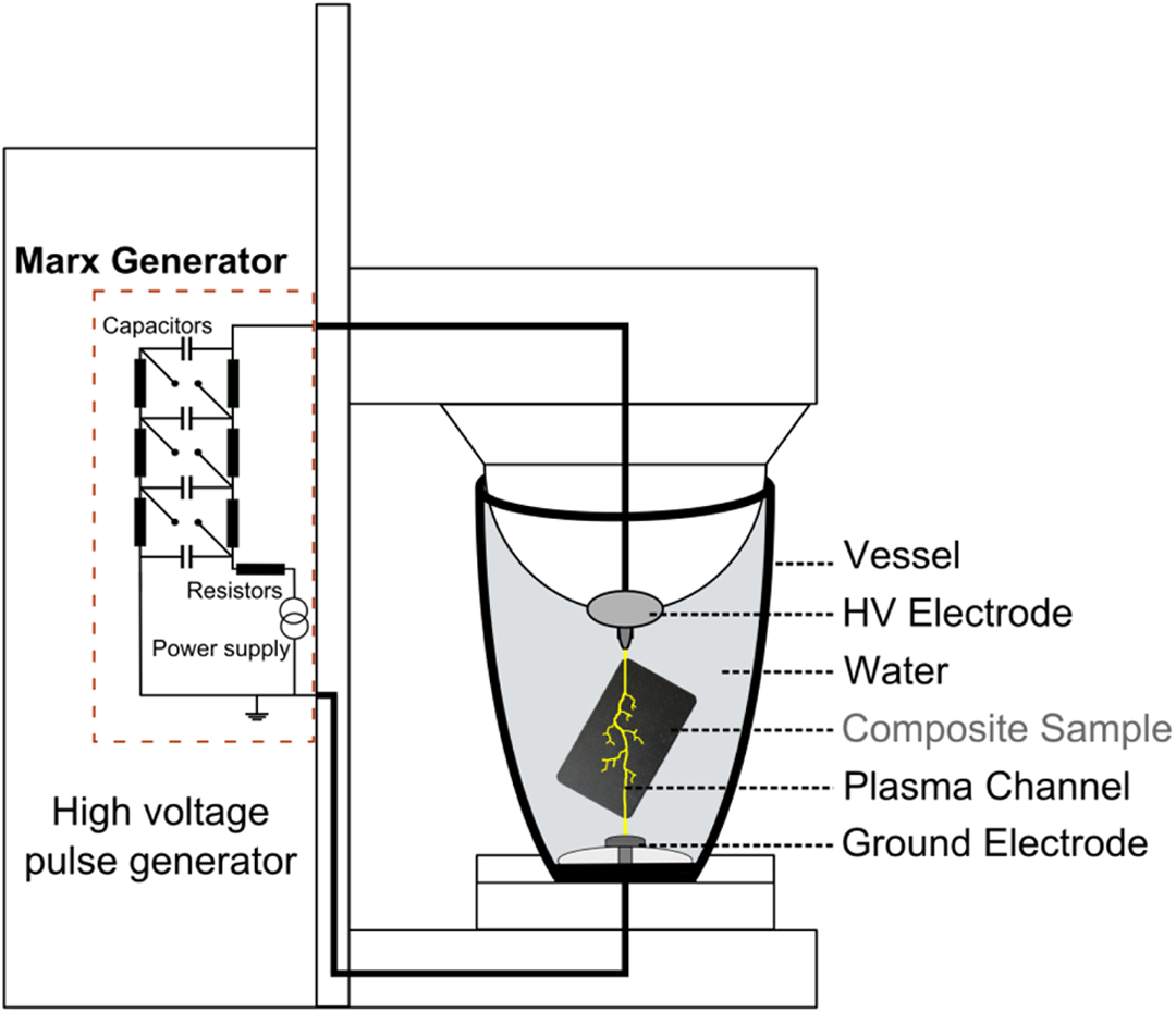
Diagram of the electrodynamical fragmentation set-up processing a composite door hinge using a Marx generator – Batch unit.
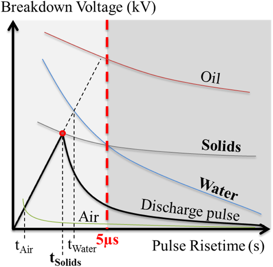
Breakdown voltage as a function of the pulse rise time. Solids have breakdown voltages lower than water below rising time of 5 µs (modified from Ref 30). The discharge goes as a priority through the solid.
The aim of this work is to use this high-voltage fragmentation process in order to fragment an aerospace grade thermoplastic composite with high contents of carbon fibre and evaluate its recyclability through a cradle-to-cradle procedure.
Materials and methods
Thermoplastic CFRP materials
The thermoplastic matrix used in this study is a PEEK from VICTREX Company (England, UK). The CFRP is supplied in unidirectional 55 vol% AS4 unsized high modulus carbon fibres (Hexcel) pre-impregnated and chopped into 20 mm long ‘chips’ by SUPREM AG (Switzerland). Lastly, to serve as a benchmark, door hinges are produced with injection granulates having 24 vol% of short AS4 carbon fibres, less than 1 mm long (Figure 4).
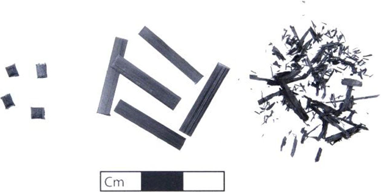
Composite PEEK/CF used to produce door hinges; left: injection granules; middle: 20 mm chopped tapes and right: fragments after high-voltage fragmentation (80 mg each). PEEK: poly(ether ether ketone); CF: carbon fibre.
Composite processing – Door hinges
Lightweight rotorcraft door hinges made of thermoplastic CFRP with PEEK matrix have been selected for the cradle-to-cradle recycling demonstration using electrodynamical fragmentation. The dimensions of the composite door hinge are given in Figure 5. The original CFRP door hinges made with the 20 mm chopped tapes are compression moulded using a non-isothermal process (Figure 6). 25 The hinges are produced by first dosing a measured quantity of thermoplastic CFRP raw material into the tool cavity (Figure 6). The tool is then closed and pressed using a vertical hydraulic press (Schwabenthan 200T, Germany) with an available 20 ton clamping force and heated over the melt temperature of PEEK at 360°C for 3 min. The part is finally cooled at a rate of 20°C min−1 and ejected from the cavity. Eguémann et al. 25 performed a complete study of the influence on the mechanical performance and standard deviation of chopped tape dimensions and process parameters. After processing, thermogravimetric analysis (TGA) measurements show that the content of carbon fibres in the door hinge is 55 vol%, and no polymer bleeding out was measured during the process with the 20 mm chopped tapes.
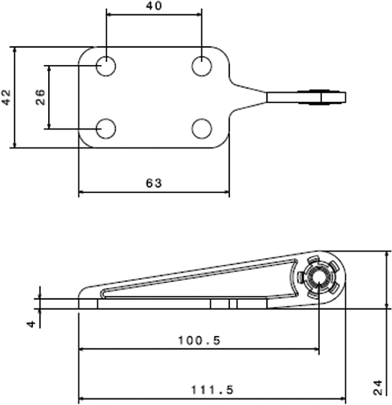
Dimensions (in mm) of the thermoplastic CFRP door hinge. CFRP: carbon fibre-reinforced polymer.
Tooling for the processing of a rotorcraft door hinge.
Electrodynamical fragmentation: Equipment
The equipment used for the electrodynamical fragmentation is a laboratory unit Selfrag Lab from Selfrag AG (Switzerland). The fragmentation is operated in a 3–4 L closed vessel. For a single door hinge, 6 cycles of 100 pulses each with an applied discharge voltage of 180 kV at a frequency of 5 Hz leads to a full fragmentation. Between each cycle, the content of the vessel is selected and separated using a metallic sieving grid with a mesh interspace of 4 mm. Fragments passing through are separated, whereas the rest is put back into the vessel. After the 6 cycles, the hinge is correctly fragmented as shown in Figure 7. Finally, the carbon powder generated is separated with a 1 mm sieving grid and captured in a paper filter (15 μm mesh).
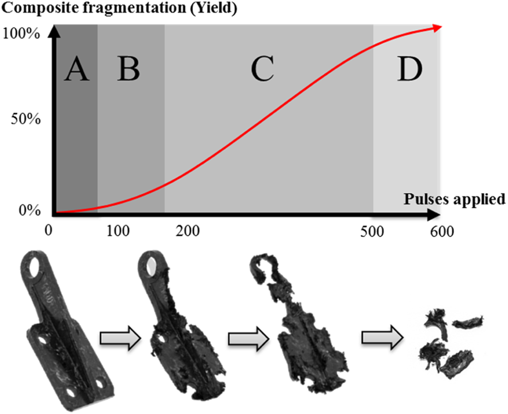
Door hinge fragmentation: Qualitative graphic of the % of composite fragmented as a function of applied pulses. A: weakening phase, B: crack propagation phase, C: fragmentation phase and D: ending phase.
Characterization methods
Microscopy
A scanning electron microscope (SEM; Vega 3 LMU, TESCAN) is used in this study in order to visualize the door hinge fractures, the composite tapes as well as the recycled fragments.
Thermogravimetric analyses
TGAs were performed with a TA Q500 (Dallas, Texas, USA) instrument in order to measure the thermoplastic polymer loss after the recycling process.
Mechanical properties
The mechanical properties of the door hinges are measured using a jig created, especially for this application. 25 The load is applied as shown in Figure 8. The door hinge is attached to a fixed support using the four holes, and the bearing ring is attached and vertically pulled down at a displacement rate of 1 mm min−1. The force is recorded with a 10 kN load cell.
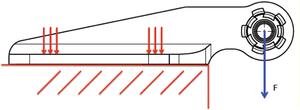
Loading conditions of the CFRP door hinge. CFRP: carbon fibre-reinforced polymer.
Results
Production of fragments
The different steps of a fragmentation process on batch mode are described in Figure 7. The value of ‘composite fragmentation’ represents the yield of fragments separated from the initial composite part in the vessel that passes through the 4 mm sieving grid. During the first cycles, only few fragments of the sample are separated mainly from the edges, and many internal cracks are locally created but not yet propagated (A: weakening phase, Figure 7). The created cracks further propagate within the hinge (B: crack propagation phase, Figure 7), as soon as the cracks reach the edges of the part, the fragment production slightly increases until a maximum fragmentation speed is reached (C: fragmentation phase, Figure 7). As the amount of composite material in the vessel is reduced after every sieving, the end process (D: ending phase, Figure 7) yields only few fragments that are quickly fragmented. The fragmentation process is usually stopped just before this phase D because the efficiency of the process decreases dramatically with a very small amount of fragments remaining in the process zone (between the electrodes). The major part of energy is then lost in the water when the discharges connect the two electrodes. The remaining non-fragmented pieces are often added in the next fragmentation batch with the next door hinge to recycle.
The chopped tapes used to produce the original door hinges and the recycled fragments after electrodynamical fragmentation of the original door hinge are presented in Figure 4. The original chip dimensions are 20 × 3 × 0.16 mm3. The best fragmentation product to ensure no down cycling would be to recover the chopped tapes with their original geometry and original configuration by only breaking the chip-to-chip adhesion created during the compression moulding process. It appears during the electrodynamical fragmentation process that the dimensions of the recycled fragments change to a smaller length and width and become thicker than the original chips.
Fragments reaching the targeted size, passing through the 4 mm sieving grid but captured in the 1 mm sieving grid, have lengths between 2 mm and 10 mm with thickness between 0.16 mm and 2 mm (Figure 9). Smaller fragments passing through the 1 mm sieving grid and captured using a paper filter (15 μm mesh) are considered as a mixed of short carbon fibres (75 vol%) and PEEK polymer such as tested with TGA. Only the fragments having the targeted dimensions are selected to be reprocessed into new door hinges using compression moulding. Thick fragments are more difficult to process. The amount of PEEK is also slightly reduced in the recycled fragments with 57 vol% carbon fibre measured using TGA. Figure 10 shows that 60 wt% of the initial CFRP door hinge can be recovered into fragments with processable dimensions. The remaining fraction represents the powder, the large fragments and finally the material loss, which integrates losses during fragmentation and sieving processes.
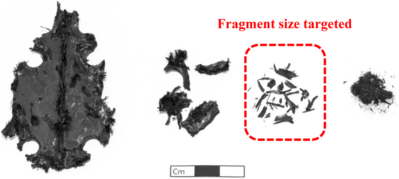
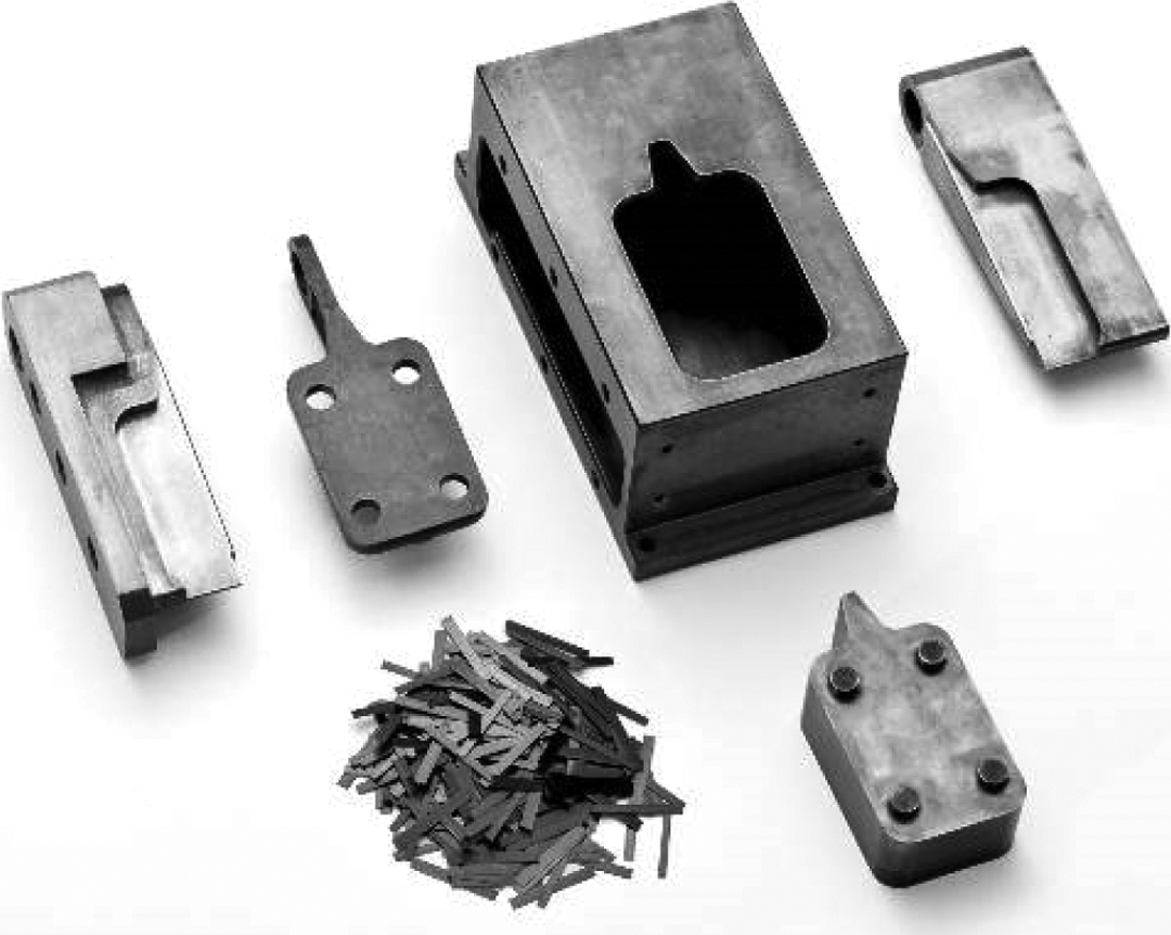
Fragments produced during electrodynamical fragmentation of the door hinge; from left to right: main part: fragmented door hinge, fragments still too large for being reused (sieve 4 mm), fragments matching the targeted dimensions (sieve 1 mm) and finally carbon powder (filter 15 µm).
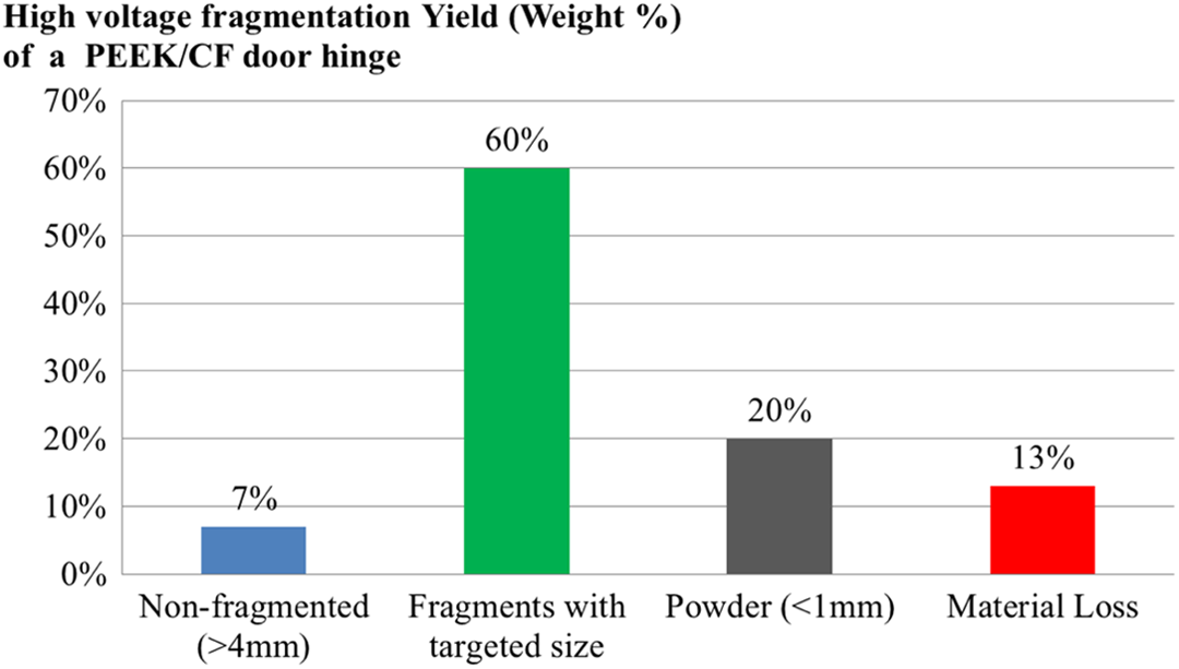
Material distribution after recycling using high voltage fragmentation of a single PEEK/CF door hinge. PEEK: poly(ether ether ketone); CF: carbon fibre.
Presentation of the fragments through SEM
The surface of chips before processing is visualized in Figure 11(a). The carbon fibres on this chopped tape are all unidirectional and well embedded in PEEK polymer (Figure 11(b)). As observed at the macroscopic level, the chips are wider than the recycled fragments (Figure 12(a)). On the recycled fragments, most of the fibres are broken and pictures at higher magnification show three different regions at the surface of the fragment (Figure 12(b) to (d)). Figure 12(b) shows fibre bundles still fully covered with polymer. The picture in Figure 12(c) displays fibres only partially covered with PEEK. Lastly, Figure 12(d) shows carbon fibres with very clean surfaces apparently free of polymer. In this case, the entire PEEK matrix was probably removed during the fragmentation process without observable damage on the surface of the fibres. This microscopy analysis indicates that the surface of the fragments is alternatively composed of naked fibres and fibres covered with polymer (Figure 12(b) and (c)). Within the recycled fragments, the fibres are still well embedded in PEEK polymer.
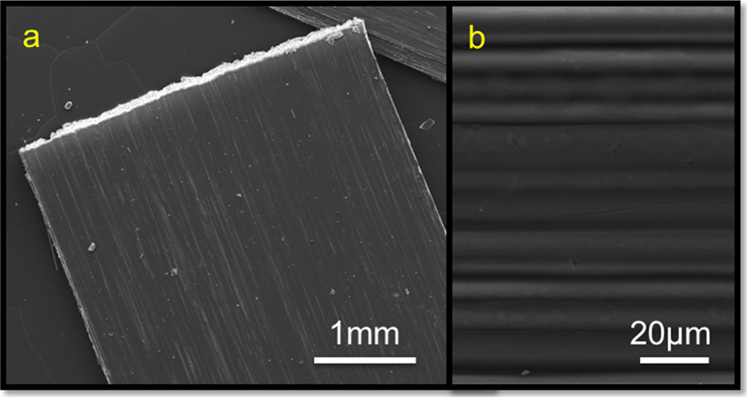
SEM pictures from the surface of a chopped tape (a) and surface with fibres well impregnated in polymer (b). SEM: scanning electron microscopic.
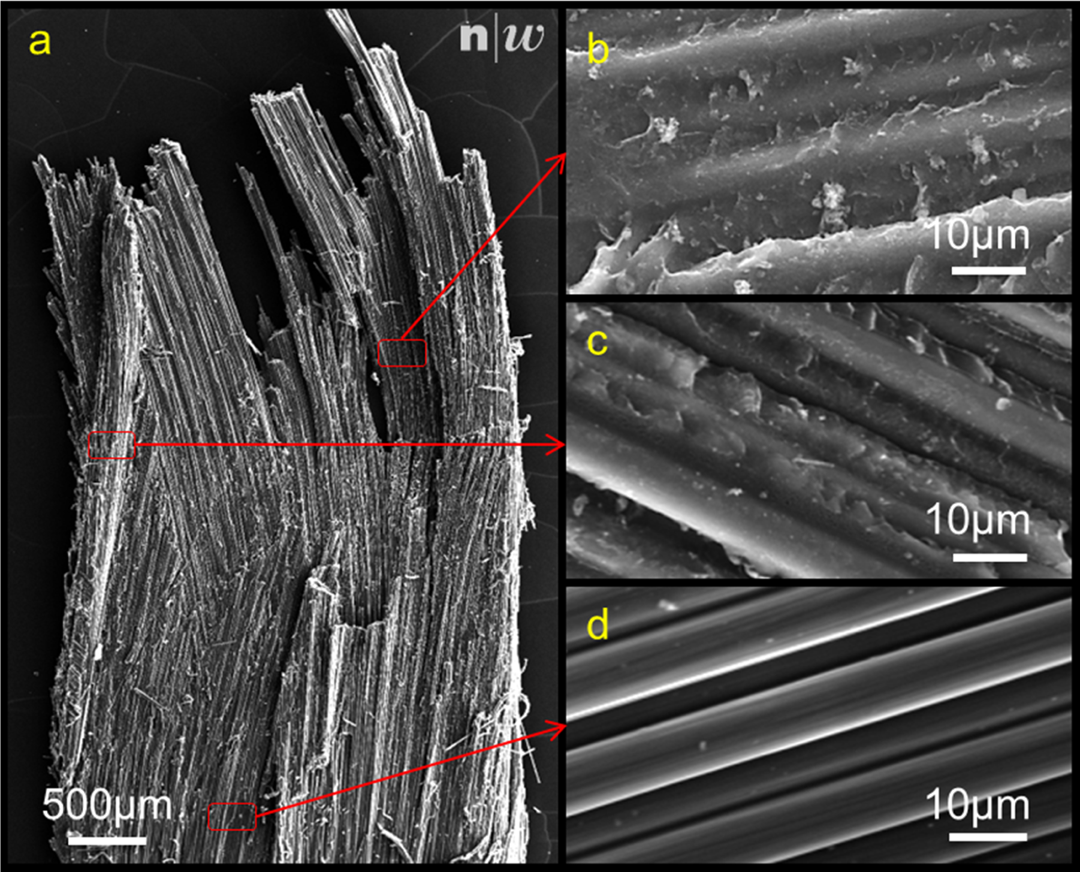
SEM pictures of a fragment after electrodynamical fragmentation (a), fragment surfaces with fibres still fully covered with thermoplastic polymer (b), partially covered by polymer (c) and free of polymer (d). SEM: scanning electron microscopic.
Manufacturing of the door hinges
The manufacturing of the recycled door hinge follows the same procedure than the original door hinges as explained previously in the materials and methods part. The aesthetics aspect of the recycled door hinge is of comparable quality to the original door hinges with smooth surfaces (Figure 13). PEEK polymer content is slightly reduced in the recycled door hinge, where TGA results measured a fibre volume content of 60%.
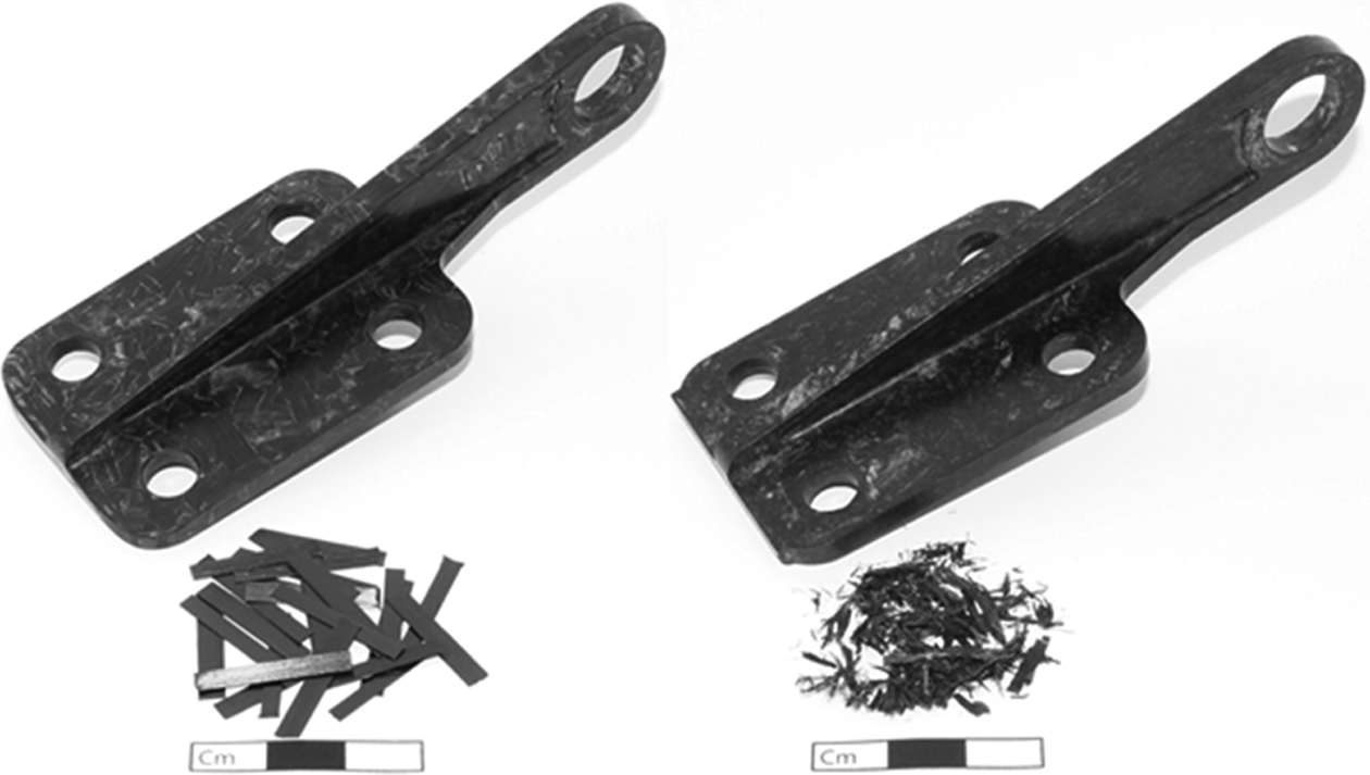
Door hinge processed with chopped tapes (left) and recycled fragments (right).
Mechanical performance of the door hinges
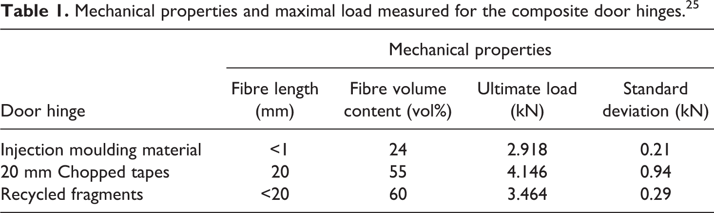
The mechanical properties of the door hinges made with recycled TPC were compared to hinges made from injection moulding or chopped tapes. The door hinges made of chopped tapes exhibit an elastoplastic deformation with a tough failure behaviour compared to the hinges made of recycled fragments showing an elastic behaviour, followed by a brittle failure (Figure 14). The hinge made of granules shows a rather elastic behaviour leading to a brittle failure with a lower slope compared to two other door hinges. The reduction in the ultimate load of the recycled door hinge was of 17% compared to the 20 mm chopped tapes but was showing 18% improvement in mechanical performance compared to the door hinges produced with injection moulding granules (Table 1).
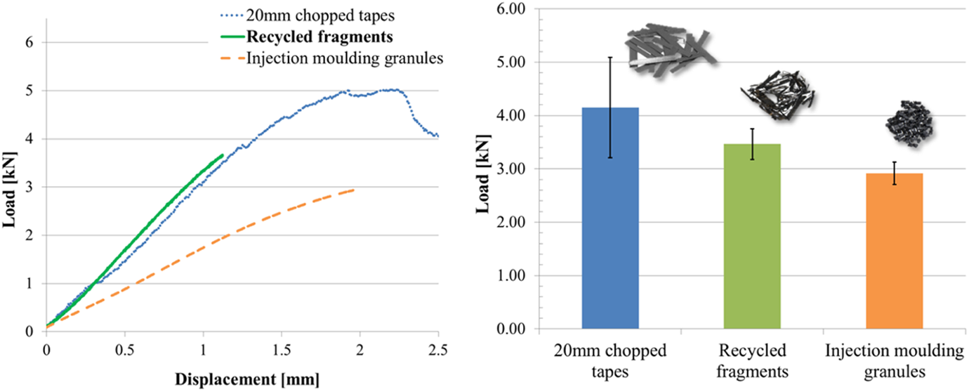
Left: typical load/deformation for the tested rotorcraft door hinges, right: graphic of the maximal load of door hinge made with granules, recycled chips and chopped tapes. 25
Mechanical properties and maximal load measured for the composite door hinges. 25
Fractography of the door hinges
Fracture profiles of the door hinges after mechanical testing were visualized using SEM in order to understand the mechanisms of rupture and the origin of mechanical performance reduction after recycling process.
In the case of the original door hinge made with chopped tapes (Figure 15(a)), the fracture is mainly propagating around the chips and is matrix driven (Figure 15(b)). The fracture mechanisms are similar to the ones in a laminate with mode I and II delaminations. The geometry of the initial chopped tapes with a very regular surface of well-aligned fibres and short thickness like in Figure 11 is still visible (Figure 15(b)). At a few positions, the fracture is also passing inside the chips, especially along the fibres showing shear failures. The overall fracture of the original door hinge shows a very good fibre/matrix adhesion and a good load transfer between both material constituents. At higher magnification (Figure 15(c)), the chopped tapes along the fracture reveal that fibres still fully embed in PEEK, suggesting rather cohesive failures in the polymer
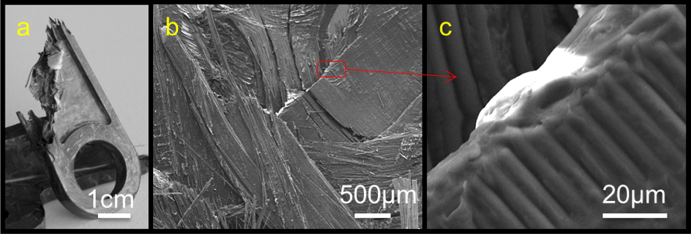
Fracture of the original CFRP door hinge (a), SEM picture of the fracture (b) and of aligned fibres with a chopped tape arrangement well embedded in polymer (c). SEM: scanning electron microscopic; CFRP: carbon fibre-reinforced polymer.
The profile of fracture from the door hinge composed of recycled fragments is visualized in Figure 16. The fracture is going along the surface of the recycled fragments as shown in Figure 16(a). The fracture is less regular and shows larger elements compared to the original CFRP door hinge (Figure 15(b)) as a consequence of the recycled fragments being thicker than chopped tapes and the fracture propagating around them. At higher magnification, three characteristic states are detected in the fracture of the recycled door hinge. The first state (Figure 16(b)) is made of randomly oriented and short fibres with polymer matrix in between. During mechanical testing, lots of fibres were pulled out from the polymer at this position, which led to marks with a very specific tunnel shape that is characteristic of adhesive failures and fibres having poor adhesion to the polymeric matrix. The second and third states (Figure 16(c) and (d)) are composed of fragments with bundles of aligned and long fibres, similar to initial chopped tapes. In those states, fibres on the surface are either free of polymer (Figure 16(c)) or well covered of polymer (Figure 16(d)). In the recycled door hinge, polymer matrix is still present between the fibres within the fragments and clusters the fibres together however there is clearly a lack of polymer at the surface of the fragments highlighting an adhesive failure between polymer and fibres.
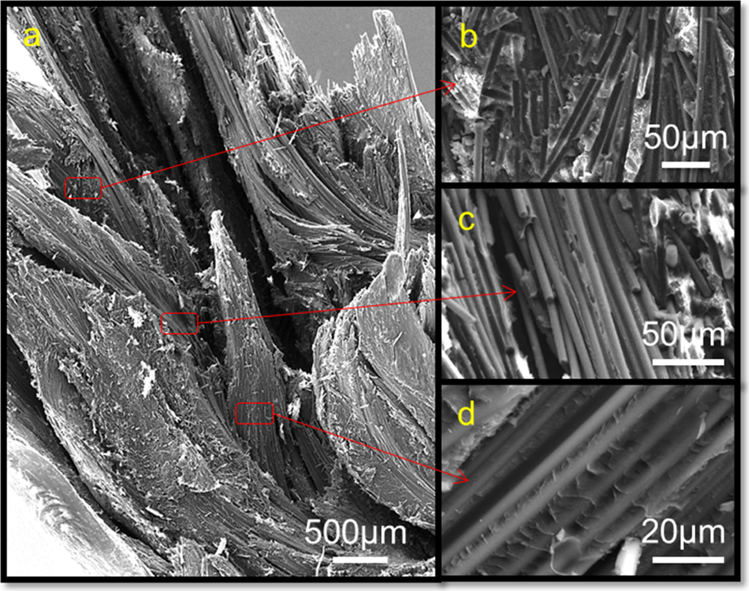
Fracture of the recycled door hinge: SEM pictures of the fracture (a); area with randomly oriented fibres with poor polymer/fibre adhesion (b), fibres aligned with polymer free surface (c) and fibres covered with polymer (d). SEM: scanning electron microscopic.
Discussion
Explanation of the fragmentation process in TPC
The main steps of an electrodynamic fragmentation of a door hinge are represented in Figure 17. Before impacting the solid, the electric discharge has to travel through the water which is ionized under very high temperatures and pressures along the generated plasma channel. Those strong conditions create pressure waves propagating in the water and in the solid. 36 At high frequencies and if the distance between the electrodes is too high, the electrical discharge travels through a large volume of water and in the gas pockets generated by the plasma, potentially bypassing the solid and thus reducing the efficiency of the fragmentation process. For this reason, a pause of several seconds in the fragmentation is required to let gases reach the surface and evaporate.
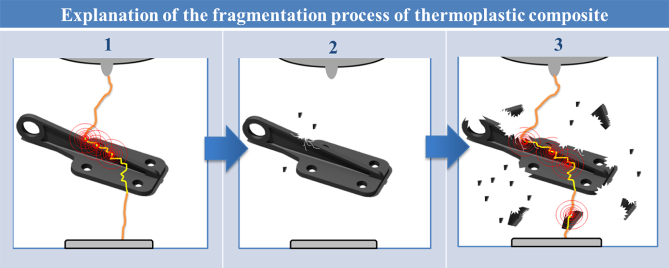
Schematic representation of electrical discharge to a door hinge in water; 1: first high-voltage discharge applied to the door hinge, 2: damages on the door hinge after discharge and 3: discharge applied to the fragmented door hinge.
In this work, interest is pushed to the comprehension of the mechanism when the electric discharge reaches the surface of the solid and penetrates it with a very high energy creating the plasma channel inside the part. The physics of the electrodynamical fragmentation process in a solid was previously explained in detail by Bluhm et al. 31 A discharge creates a plasma channel in the solid with temperatures and pressures up to 10,000°C and 1010 Pa, respectively. Inhomogeneities in the material such as the difference in mechanical, electrical or chemical properties influence the propagation of the sparks in the part. In the case of inclusions with high permittivity, the electrical discharge will be attracted and follow their material boundary which will separate the inclusion from the solid. In the composite door hinge, the carbon fibres play this key role without carbon fibres, and Lisithyn et al. 36 have already observed that uniform dielectric materials such as polymers could not be broken down in water. In a TPC, the effects of high-voltage discharges are slightly different from what could be found in the literature for other materials. By analysing a composite plate made with the same 20 mm chopped tapes after a single discharge (Figure 18(a)), the discharge goes through the part without creating fragments and only the top and bottom surfaces of the impact zone are affected.
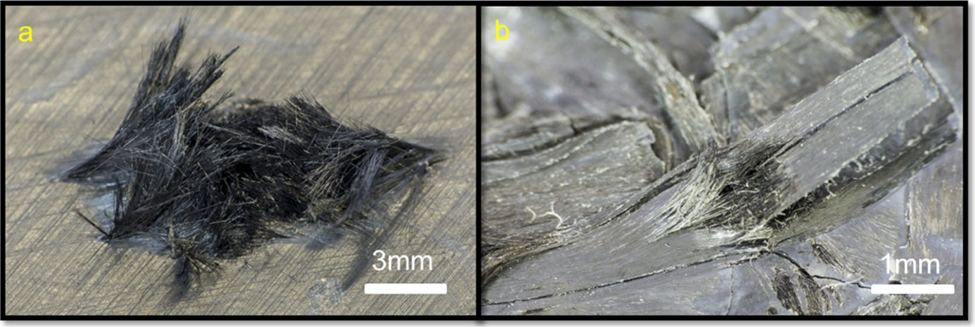
Impacts of high-voltage discharges (180 kV) on chopped tapes PEEK/CF composite surfaces. a: First discharge on a plate leading to a large damaged area (bottom surface) and b: random impact during the door hinge fragmentation (after 300 discharges) leading to the partial delamination of a composite tape. PEEK: poly(ether ether ketone); CF: carbon fibre.
The impact on the surface at 180 kV is very similar to the damage areas of an epoxy-based CFRP affected by 50 kV discharges simulating lightning strikes on airplanes in recent published works. 37,38 Some observations can be made from the pictures of a single impact (Figure 18): for the first discharge applied to the composite, the fibres are free of polymer and broken at the position of the impact (Figure 18(a)) leading to a large damaged area. When a single impact is taken randomly at the surface of the composite part after 300 discharges (Figure 18(b)), the composite layers are lifted up around the impact zone and partially delaminated from the main part.
According to Ogasawara et al., 37 the first observation is the direct consequence of the induced temperatures along the discharge channel that are far higher than the degradation temperature of the polymer matrix and sublimation temperature of carbon fibres. The temperature induced in the CFRP varies as a function of its distance from the plasma channel: according to Bluhm et al., 31 the discharge creates a plasma channel in the solid with a temperature up to 10,000°C. Ogasawara et al. 37 reported that during a lightning strike of a composite as soon as the temperature exceeds 3000°C, carbon fibres will break through sublimation and will cause a recession of the surface similar to what we can observe in Figure 18, and we call it the first fragmentation failure mode (zone I in Figure 19). Patel et al. 39 described the mechanisms of carbon fibre-reinforced PEEK polymer degradation depending on temperature and atmosphere. PEEK polymer melts at 343°C and thermal degradation starts from 580°C; PEEK pyrolysis can be established in the near region of the plasma channel path and is defined as the second fragmentation mode (zone II, Figure 19). Ogasawara et al. 37 also observed that the production of pyrolysis gases leads to a fast increase of the gas pressure close to the discharge channel that produces a rapid expansion of the interlayer gaps and thus delaminates the surrounding plies in mode I. We indicate this as the third fragmentation failure mode (zone III, Figure 19). Finally, the fourth fragmentation failure mode (zone IV, Figure 19) comes from pressure waves transmitted in the material from high internal pressures built up in the plasma channel. This fourth fragmentation failure mode has been widely reported in literature and is considered as the main cause of material fragmentation for rather fragile materials such as minerals or ceramics with low tensile properties. The pressure induced in the plasma channel was previously estimated between 1 and 10 GPa31 and consequently launches a pressure wave that propagates around the plasma channel with a decreasing intensity as a function of the distance travelled in the material. This pressure wave in the material is transformed into a compressive wave that also turns to a tensile wave by reflection that leads to the destruction of the material when the stress overcomes the tensile/compression strength of the material. 30 Carbon fibres and PEEK polymers have a tensile strength of 4.5 GPa and 0.1 Gpa, respectively. As a result, in the very close area around the plasma channel, the carbon fibres and the PEEK polymer can be mechanically broken. The intensity of the pressure waves decreases rapidly with the distance from the plasma channel and, from a short distance, only the PEEK polymer is cracked. The carbon fibres propagate and reflect the pressure waves without being further affected.
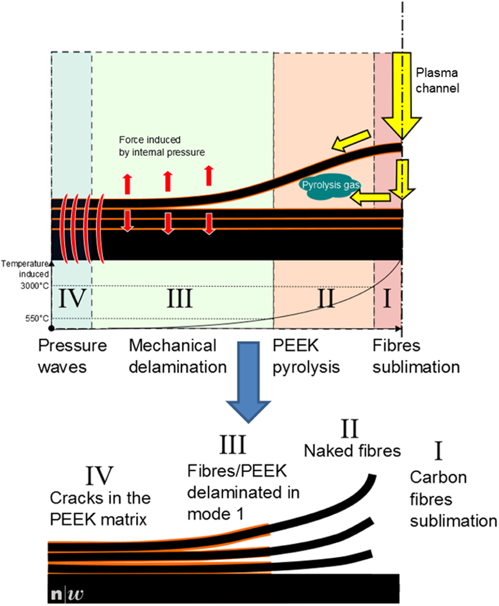
Schematic illustrations of the mechanism of fragmentation induced by HV pulses (modified from 37 ). HV: high voltage.
Gao and Kim 40 studied fracture surfaces of CFRP with the same semi-crystalline PEEK matrix and unsized carbon fibre as in the present study. He demonstrates that cooling rates below 120°C min−1 during the compression moulding process are sufficient to induce a preferential nucleation and epitaxial growth of PEEK spherulites from the fibre surface favourably influencing the interphase interaction and fibre/matrix load transfer. As a result, fracture surfaces from these slow cooled materials show fibre surfaces covered with rough layers of crystalline PEEK resulting from matrix cohesive failure in the more amorphous surrounding phase. With a compression moulding cooling rate of 20°C min−1 in the present case, we observe similar fracture surfaces profiles as reported by Gao and Kim 40 all along the fracture surfaces of the original tested door hinge with chopped tapes (Figure 15) and also on some areas of the fracture surfaces of recycled fragments (Figure 16(b)). This confirms that pure mechanical fragmentation failure modes without temperature elevation are at the origin of fragmented surfaces showing fibres still embedded in the nucleated PEEK spherulites as observed in third and fourth fragmentation failure modes. Fracture surfaces showing naked fibres may then have been generated by the second fragmentation failure mode inducing PEEK pyrolysis.
Decrease of mechanical performance after electrodynamical fragmentation
As shown in Figure 14, the recycled door hinges exhibit a slight decrease of the mechanical properties and brittle failures that have various origins. In samples manufactured with chopped tapes, the mechanical properties depend on the relation between the chips dimensions and the part dimensions as reported by Eguémann et al. 41 This relation is also referred as the size effect, where samples with longer chopped tapes exhibit not only higher strength but also larger scatter in results. As observed, the recycled door hinge is composed of fragments with shorter fibre lengths compared to the original CFRP door hinge, which leads to lower values in strength and scatter. After mechanical testing, the recycled door hinge exhibits a thicker non-repeated fracture (Figure 16(a)) in comparison with the original door hinge (Figure 15(b)). This is mainly due to recycled fragments being thicker than the chopped tapes. An early breakage in the recycled door hinge is suggested because the fracture passes through fewer material boundaries and rapidly propagates compared to the CFRP door hinge. This change in mechanical properties may come not only from shorter carbon fibres and thicker fragments but also from a possible lack of fibre/matrix adhesion, where the surfaces of recycled fragments were produced by the second fragmentation failure mode.
The surfaces of the recycled fragments are not as homogenous as the chopped tapes and will perhaps require adapted compression moulding parameters such as longer processing times in order to allow to the PEEK contained within the fragments to flow and fill gaps between the fragments. Finally, the nucleation effect can also be enhanced at the surface of the fibres via thermal treatments, consequently improving the fibre/matrix adhesion as it was observed in the CFRP door hinge before recycling process.
Conclusions
In this report, the recycling feasibility of high-content carbon fibres-reinforced thermoplastic is demonstrated without machinery wear as experienced by the use of shredders whilst keeping relatively long fibres within the fragments. Door hinges were successfully produced with 100% recycled materials using the same compression moulding set-up as for the original hinges and without any post-processing applied on the fragments between the recycling and the reprocessing. Door hinges with recycled material exhibit a decrease of only 17% of the mechanical performance compared to novel chopped tapes door hinges and 18% increase in mechanical performance for door hinges produced with injection moulding granules. These results place recycled fragments at an attractive economic value between chopped tapes and injection moulding granules. After fracture analysis, it has been clearly demonstrated that this reduction of mechanical performance has two main sources. Firstly, the geometry and dimensions of the recycled fragments are less optimal than chopped tapes. Secondly, the recycled fragments exhibit a localized loss of polymer at their surface due to thermal pyrolysis reducing the adhesion and fibre/matrix load transfer.
The quality of those fragments must be improved by adapting process equipment and parameters for thermoplastic CFRP, fragmentation parameters encouraging the third and fourth fragmentation failure modes.
The processing parameters of the compression moulding process needs to be adapted to recycled fragments as well. In order to compensate the lack of polymer at outer surfaces of fragments, the time spent over the melting temperature of PEEK could be increased. Additionally, the applied pressure could also be increased to let the PEEK matrix contained within the fragments flow within the dry portions present between the fragments.
An industrial adaptation of the batch electrodynamical fragmentation process avoiding the time intensive sieving with a continuous flow working machine dedicated to CFRP recycling is under development in collaboration of the European research project CLEAN SKY Joint Technology Initiative (JTI) and Selfrag AG. Thermoplastic CFRP are good candidates for replacing thermoset CFRP and metallic parts in aerospace applications, not only due to their low density, excellent mechanical properties and processability but also regarding the new perspective of recycling that is offered through the electrodynamical fragmentation.
Footnotes
Acknowledgements
The authors would like also to acknowledge the Selfrag Company for the use of the high-voltage fragmentation equipment and Eurocopter Germany for supplying the study case.
Declaration of Conflicting Interests
The author(s) declared no potential conflicts of interest with respect to the research, authorship and/or publication of this article.
Funding
The author(s) disclosed receipt of the following financial support for the research, authorship and/or publication of this article: The research leading to these results has received funding from the European Union’s Seventh Framework Programme (FP7/2007-2013) for the Clean Sky Joint technology initiative under grant agreement n°CSJU-GAM-ED-2008-001.