
Abstract
To reveal the deformation, strength, and failure modes of woven textile sandwich composites (WTSCs), test methods suggested by national standards were referenced and discussed to carry out flatwise and edgewise compression experiments, uniaxial stretching experiments, and three-point bending experiments according to the structural characteristics of WTSC. Strength and failure modes of WTSCs in flatwise compression and uniaxial tension were acquired. Anisotropy and size dependency of strength and failure modes of WTSC panels in edgewise compression were revealed. Strength of weft-compressed panels has few variations when the length is smaller than 60 mm and then decreases obviously when the length is over 60 mm, accompanying with the failure modes turning from crushing, fracture to buckling. Progressive crushing and bending fracture are two observed post-failure modes. Two competing shear failure modes and facesheet failure were observed in three-point bending experiments. Shear strength of the woven core of WTSC was deduced by beam flexure. To acquire facesheet failure mode by long beam flexure, the span should be above 36 times the thickness of the panel.
Keywords
Introduction
Fiber-reinforced polymer (FRP) sandwich panels have been widely used in aerospace, marine, wind turbine blade, and construction and building applications. 1 –3 Their lightweight, high strength, and durable characteristics make them a strong candidate for the construction industry. To overcome delamination problems typically encountered in traditional sandwich panels, Reis and Rizkalla 4 presented an innovative three-dimensional (3-D) FRP. With integrated woven struts in the core, as shown in Figure 1, woven textile sandwich composites (WTSCs) prove to be efficient materials with high skin–core debonding resistance. 5 –10 Multipurpose WTSC panels produced by Nanjing Fiberglass Research & Design Institute are shown in Figure 1. Applied in decorative stone, WTSC-based panels lead to over 50% weight cut down. Quasi-static flatwise compression experiments have been performed to reveal the ductile deformation mechanism as well as the energy absorbing mechanism. 11 Low-velocity flatwise compression tests were performed to reveal the dynamic behavior and strain rate effect of WTSCs. 12,13 According to the research, the woven skins of WTSCs are usually not strong enough when bearing load. Li et al. 14 revealed compression responses of pyramidal truss core sandwich panels, with Euler macrobuckling, shear macrobuckling of the core, skin microbuckling, skin wrinkling, skin crushing, and other failure modes discussed. Some similar analyses on the failure modes 15,16 have been also reported before. Karahan et al. 17 discussed static behavior of 3-D integrated core sandwich composites subjected to three-point bending load. Fan et al. 18 revealed six typical load–displacement curves for WTSC panels under bending load, where skin fracture induced brittle failure. However, edgewise compression and shear properties of WTSC panels have been seldom reported, so it is meaningful to fill this blank.
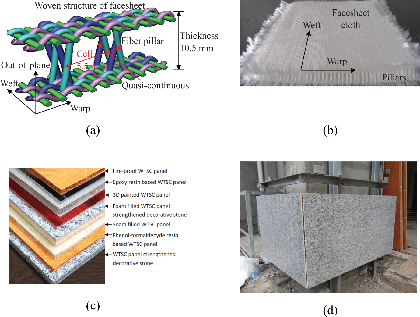
(a) Woven structure, (b) woven sandwich cloth before resin infusion, (c) typical WTSC panels, and (d) decorative composite stone applied in column construction.
WTSC panels have been applied in floors, building decorative panels, wind deflectors, 12,19 blades, carbodies, and boats. However, due to their anisotropy and asymmetry, traditional test methods are required to be explored and discussed in order to study the mechanical properties and reveal the structural characteristics of WTSC panels. In this study, a novel lightweight fireproof material made of phenol–formaldehyde (PF) resin-based WTSC was introduced, and its edgewise and flatwise compression behaviors, stretching behaviors and bending behaviors were studied to give reasonable suggestions to the test.
Structures
In this research, WTSC panels are made of glass fibers and compounded with PF resin, as shown in Figure 2 from the warp view and the weft view, respectively. Facesheets and fiber pillars in the woven core were both solidified by fireproof PF resin. Fireproof is the basic requirement for WTSC when applied in constructions. As an integrated woven structure, fibers in the core are woven together with fibers in the skin so as to improve the interface property and reduce debonding failure. Density of the woven panel is 4.38 kg m−2. Thickness of the sandwich panel is 10.5 mm in average, with two skins 1.52 mm and 0.92 mm thick, respectively. Neighboring fiber pillars with a thickness of 1.5 mm in the warp direction have a distance of 5.5 mm.

(a) Dimension of PF resin-based panel from warp view and weft view, respectively, and (b) flatwise compression curves.
An important characteristic of the PF resin-based WTSC is the anisotropic structure of the core. In the warp direction, fiber pillars in the core resemble the eight-shape, and in the weft direction fibers look dense and quasi-continuous. The two skins also have different thicknesses. Due to this geometrical asymmetry, WTSC is anisotropic and has quite different mechanical behaviors in weft and warp directions.
Experimental studies
Flatwise compression behaviors
According to GB/T 1453-2005 standard, 20 dimension of the sample must be no less than 60 × 60 mm2 or larger than four times the dimension of a unit cell in the core. For WTSC panel, dimension of the unit cell is quite small. To satisfy the requirement of GB/T 1453-2005 standard, the length and the width of the sample must be greater than 60 mm. In experiments, they were set to be 100 mm. This area is also satisfied with the requirement of ASTM C365/C365M-11 standard, 21 which requires the area to be between 2500 mm2 and 10000 mm2 for minimum cell size larger than 3.0 mm. Compression experiments were carried out on CSS44100 test machine at a loading rate of 0.2 mm min−1. Compression strength of the panel (σcs) is calculated from the experimental data as:
where Pcr is the peak load applied to the panel and Ac is the compressed area of the panel. WTSC panel is ductile under flatwise compression. As shown in Figure 2, the load–displacement curve exhibits four characteristic stages, namely, elastic deformation, softening, stable deformation, and densification. 22 Compression strength of the panel varies from 2.5 MPa to 3.2 MPa but exhibits identical failure style. The mean crushing force (Pmc) is defined by the energy absorption per unit crushing distance as:
where P and δ are applied load and corresponding displacement, respectively, and Δ is the crushing distance before densification where the load is equal to the peak, as shown in Figure 2. The corresponding strain is defined as densification strain. Tested mean crushing force varies from 14.9 kN to 19.2 kN. Ratio of the mean crushing force to the peak load (ξ) is defined as:
which reflects the ductility of the panel and is applied to evaluate the energy absorption ability. The ratio is about 0.60, indicating that WTSC is much more ductile than most carbon fiber-reinforced lattice truss materials. 22 Its energy absorption in crushing varies from 0.82 J cm−3 to 1.02 J cm−3.
Uniaxial stretching behaviors
Uniaxial stretching property of WTSC panel was tested along warp and weft directions, respectively, as shown in Figure 3. According to GB/T 1447-2005 standard, 23 the panel is 250 mm long and the clamping is 50 mm long, as required by ASTM C363/C363M-09 standard. 24 As the compression strength of the core structure is small, the core was filled with epoxy resin at the clamping ends to guarantee tight clamping, as shown in Figure 3. The experiments were carried out on CSS44100 test machine at a loading rate of 2 mm min−1.
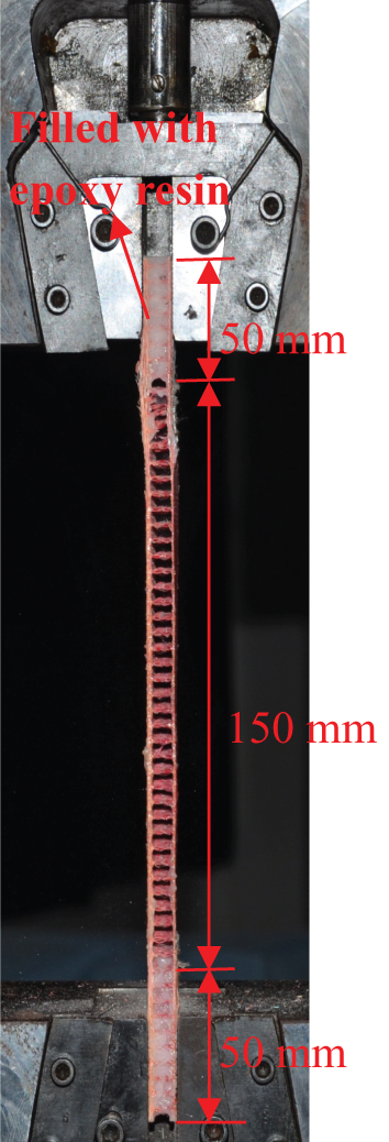
Adjusted stretching test method for WSTC panel according to GBT 1447-2005 standard.
Stretching curves are plotted in Figure 4. Skin fracture was firstly observed near the mid-span. The failure is brittle. Tensile strength of the panel (σpt) is calculated from the experimental data as:
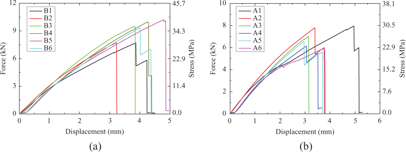
Stretching curves along (a) weft and (b) warp direction.
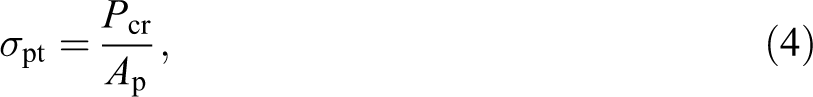
where Ap is the cross-sectional area of the panel. Tensile strength of the panel skin (σst) is calculated from the experimental data as:
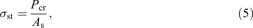
where As is the cross-sectional area of the skin. Weft-stretched panels have strengths varying from 29.3 MPa to 38.9 MPa. Neglecting the core, tensile strength of the skin varies from 126.1 MPa to 167.4 MPa. Warp-stretched panels have strengths varying from 22.5 MPa to 30.5 Mpa, and the tensile strength of the skin varies from 96.8 MPa to 131.1 MPa. So, weft-stretched panels are a little stronger, which comes from the woven structure of the skin, as shown in Figure 2, where the waviness of warp fibers is more obvious. Elastic modulus (E) of the panel is directly calculated from the slope (σ/ε) of the stress–strain (σ-ε) curve. In experiments, it is 1.9 GPa and 1.63 GPa for weft-stretched and warp-stretched panels, respectively. Modulus of the corresponding skin is about 8.2 GPa and 7 GPa, respectively. For WTSC panels, woven structure of the skin lessens their tensile strength and stiffness, so the skin should be strengthened in some cases.
Edgewise compression behaviors
Test procedure
According to GB/T 1454-2005 standard, 25 in edgewise compression the sandwich panel should at least include four periodic cells in width, and the unsupported height of the panel should be smaller than six times of the thickness of the panel, about 63 mm in this case. In ASTM C364/C364M-07 standard, 26 the length must be smaller eight times the panel thickness. The width should be greater than 50 mm, or twice of the thickness, or four times of the width and smaller than the length. Acceptable failure modes include facesheet bucking failure, facesheet dimpling failure, facesheet compression failure, core compression failure, and core shear failure. End failure is unacceptable.
The unsupported height and width were set to be 60 mm and 100 mm, respectively, as shown in Figure 5. To reveal the height influence, panels with unsupported heights of 10, 20, 40, and 80 mm were compressed along the weft direction and the warp direction, respectively. Edgewise compression was performed on CSS44100 test machine at a loading rate of 2 mm min−1.
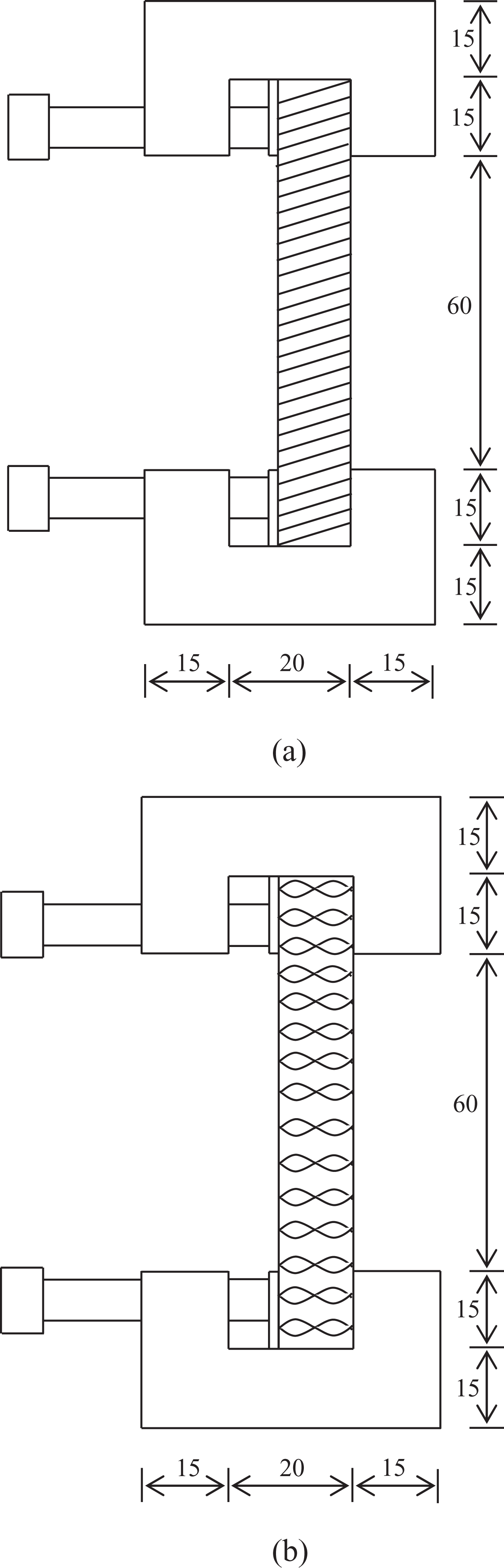
Standard compression set up suggested by GB/T 1454-2005 standard for (b) weft and (c) warp panels (in millimeter).
Test results—Height influence
Panels of 60 mm height
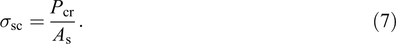
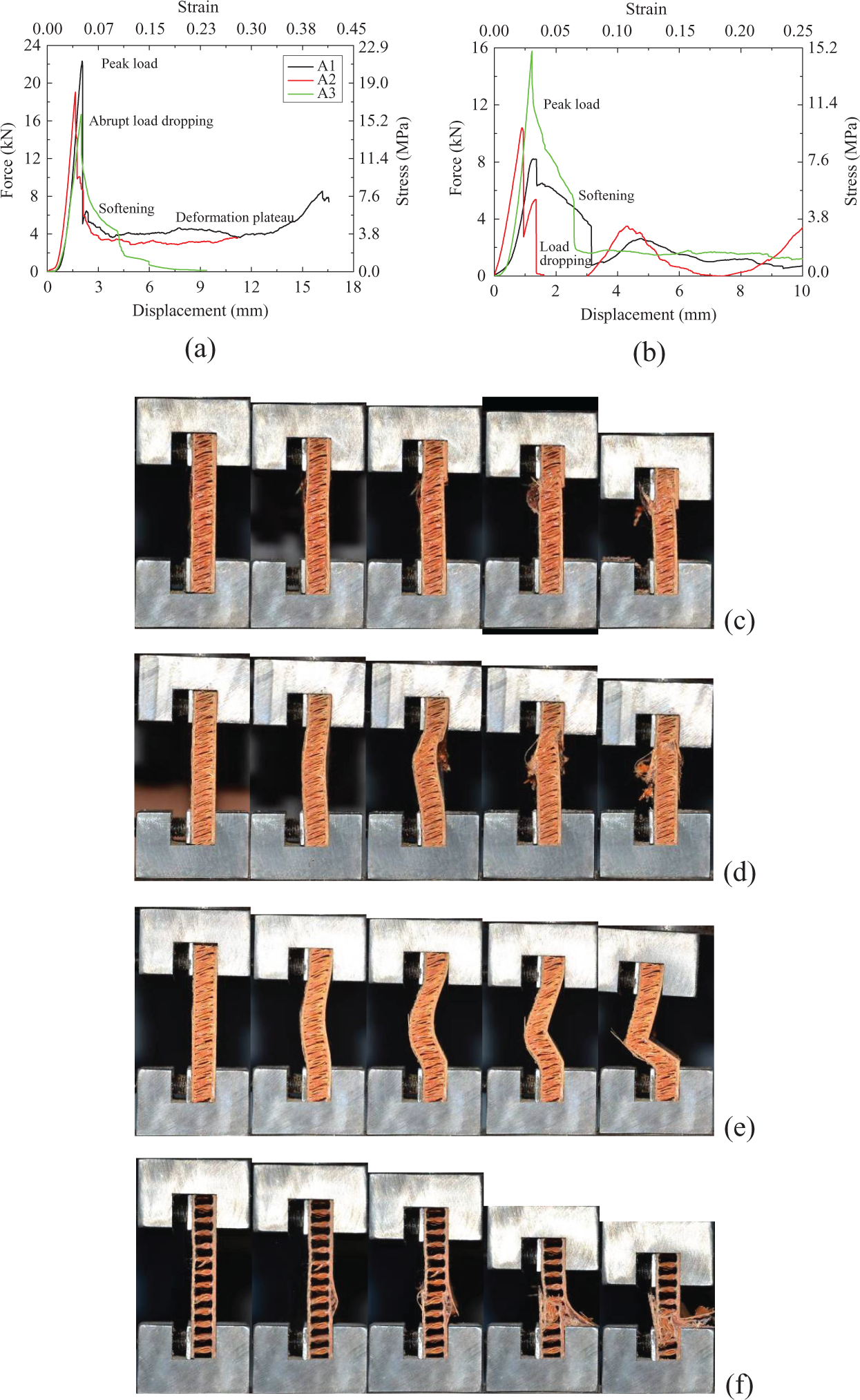
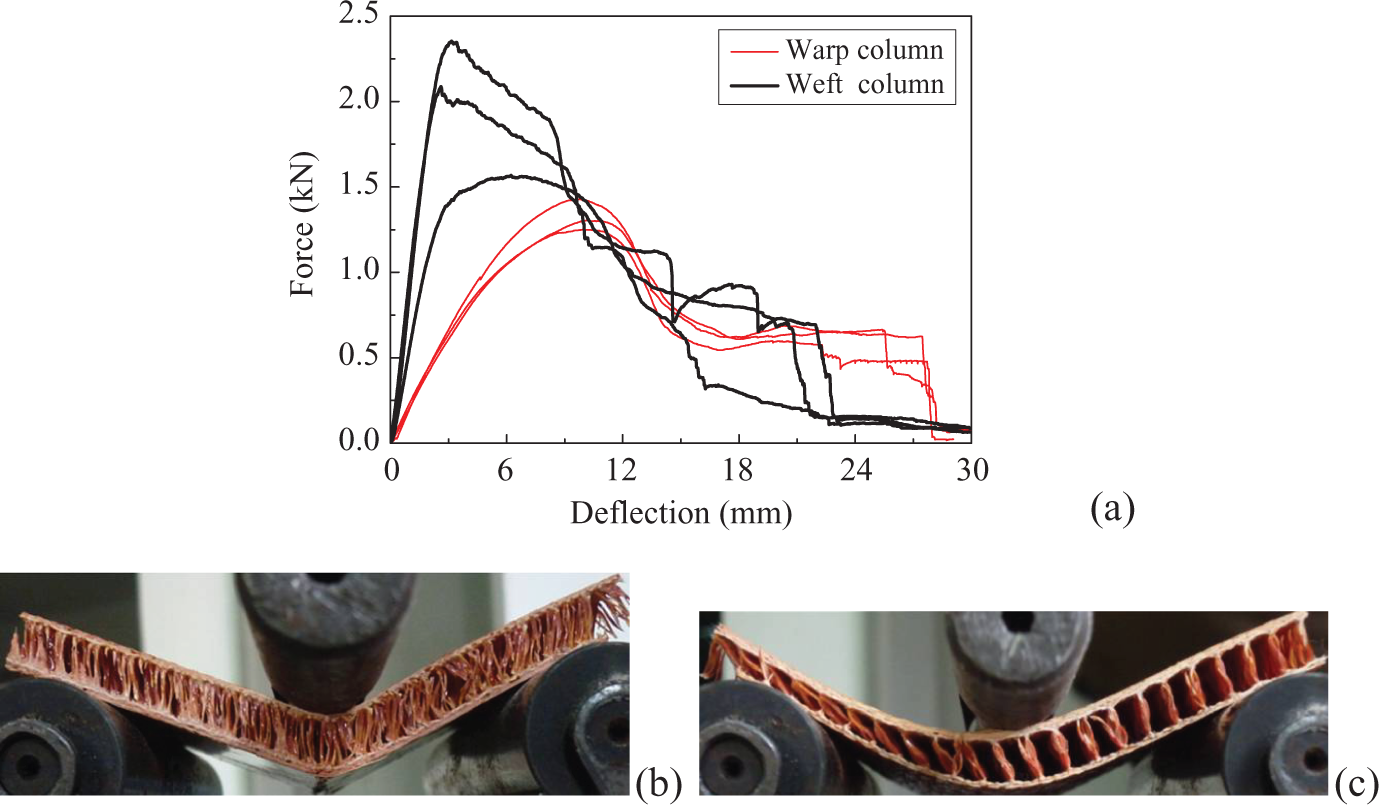
Panel of 60 mm height is the standard sample according to GB/T 1454-2005 standard. The panel exhibits brittle failure mode, as shown in Figure 6(a) and (b). Compression strength of the panel (σpc)is calculated from the tested data as:
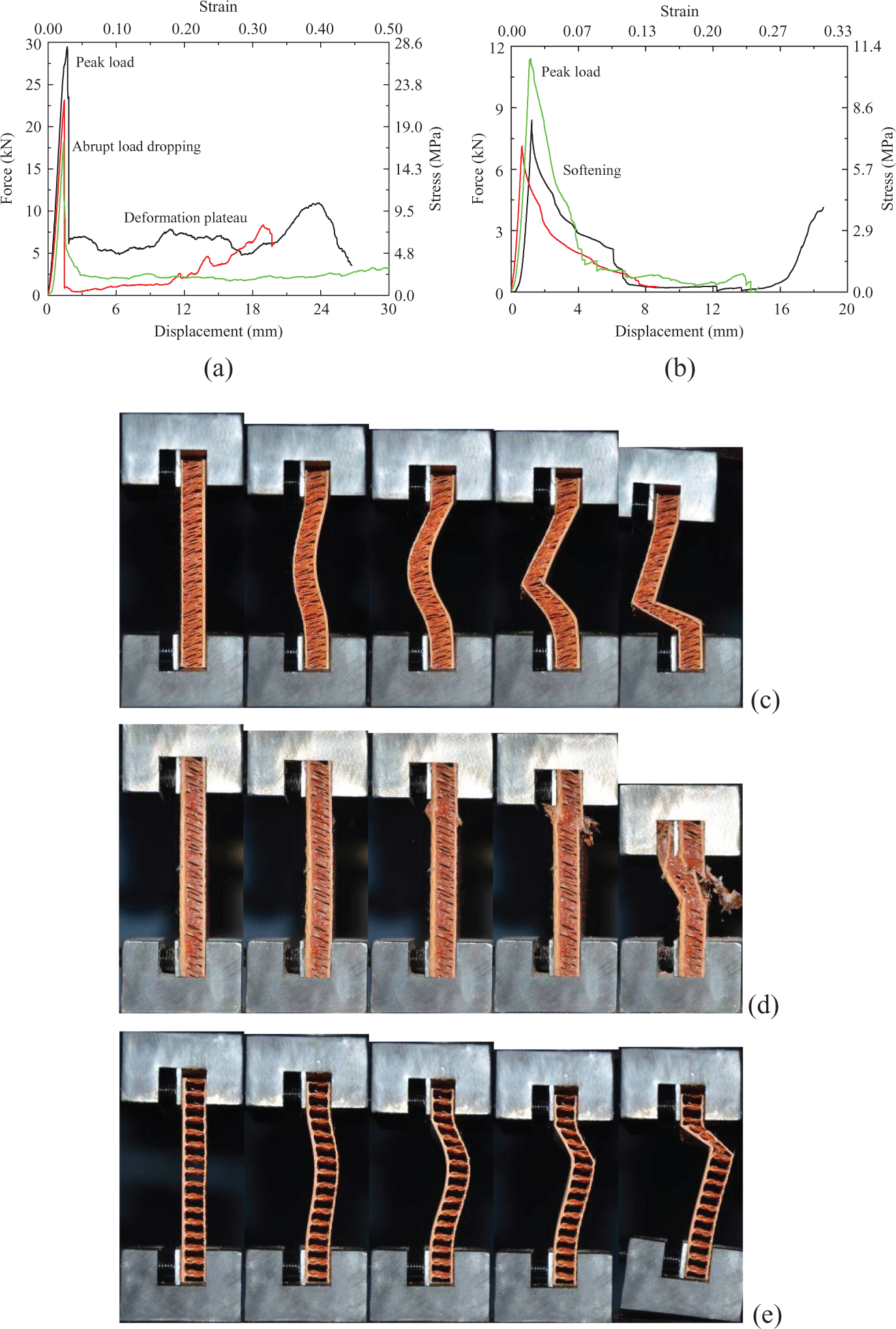
Compression of panels of 60 mm height: (a) deformation curves of weft panels, (b) deformation curves of warp panels; (c) buckling failure, (d) compression fracture failure of weft panels, and (e) buckling failure of warp panels.
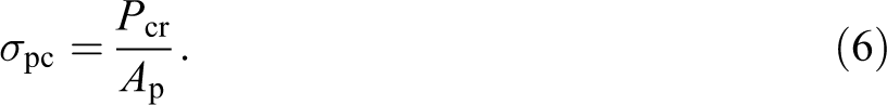
Compression strength of the skin (σsc) is calculated from the experimental data as:
For weft panels, strength failure occurs firstly at the thick skins, as shown in Figures 6(c) and (d), leading to an abrupt load drop. The strength of the panel varies from 28.1 MPa, 22.1 MPa to 17.3 MPa. The compression strength of the skin varies from 120.9 MPa, 95.1 MPa to 74.5 MPa, a little smaller than its tensile strength. Two post-failure modes were observed in experiments. One is post-buckling, as shown in Figure 6(c). Near the end, cracked skins behave as a pin-joint, and the panel is bended. The thinner skin is stretched, while the thicker skin is compressed. The other post-failure mode is the progressive crushing of the core, as shown in Figure 6(d). The skins have continuous fracture. In post-failure, the deformation curve has a plateau, although the stress level is not high. Both of these two post-failure modes are brittle.
Warp-loaded panel has a bending fracture induced by global buckling, occurring at the skin between two neighboring piles, as shown in Figure 6(e). Due to global buckling and bending failure, the strength, varying from 10.9 MPa, 8.09 MPa to 6.84 MPa, is much smaller compared with that of weft-compressed panels. Its post-failure mode is also brittle.
Panels of 40 mm height
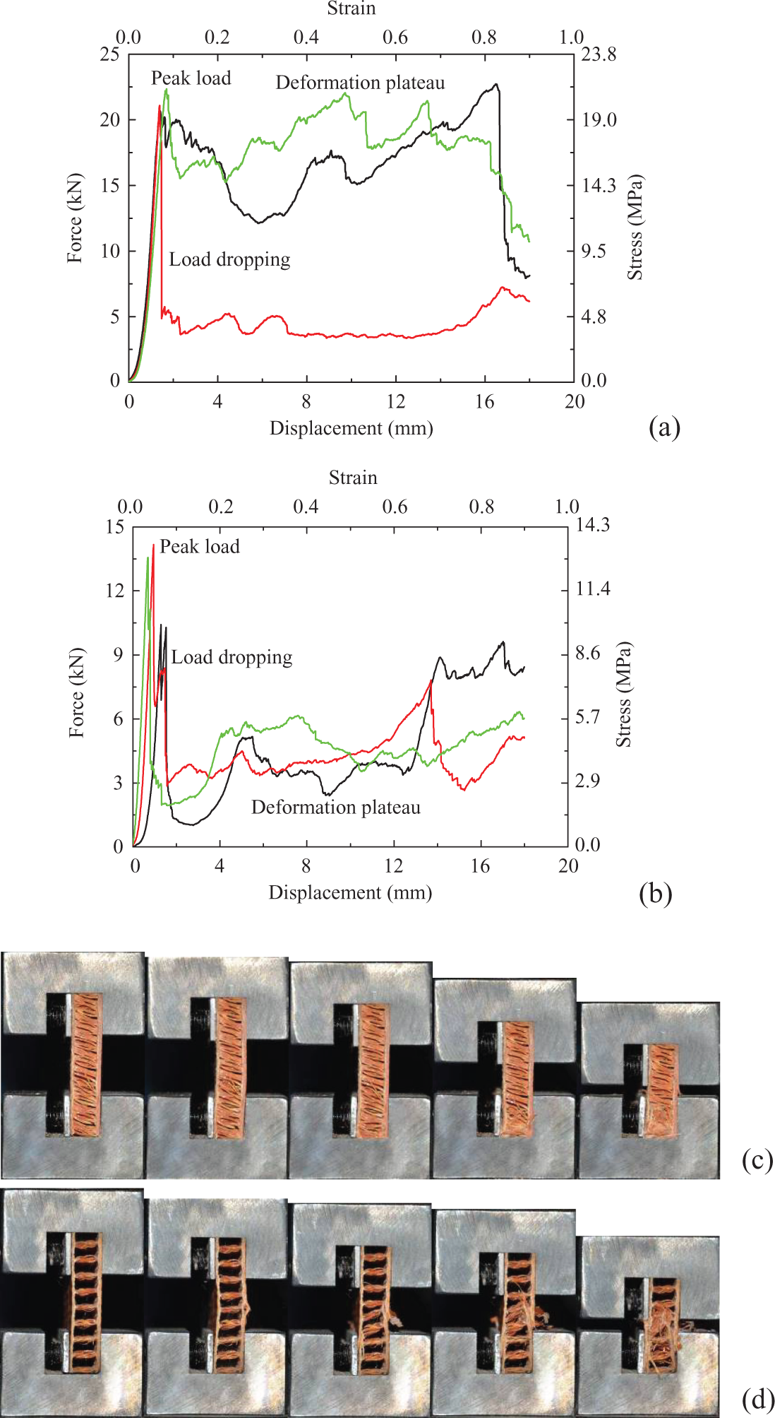
Panels of 40 mm height and 100 mm width exhibit brittle failure modes, as shown in Figure 7. Deformation curves are characterized by softening and abrupt drop of the peak load. Weft-compressed panels are controlled by strength failure, with strength varying from 21.3 MPa, 18.2 MPa to 16.0 MPa, comparable to weft panels of 60 mm height. But they have complex post-failure modes. The first is the progressive crushing failure of the core, where the skins pierced into the core. Due to the low strength of the core, the stress of the deformation plateau corresponding to this mode is rather low. The second failure mode is hybrid, with progressive core crushing following bending failure. The deformation curve has low-level stress plateau. The last post-failure mode is bending fracture without deformation plateau.
Compression of panels of 40 mm height: (a) deformation curves of weft panels; (b) deformation curves of warp panels; and failure maps of weft panel (c) A1, (d) A2, (e) A3, and (f) warp panel.
Warp-compressed panel fails at mono-cell skin fracture after the thicker skin is firstly compressed to local buckling. After the fracture of the buckled skin, the thinner skin was then cracked, and the warp core was pierced by cracked skins. Due to local buckling, warp-loaded panels have much smaller strength, varying from 15.0 MPa, 9.90 MPa to 7.84 MPa, a little greater than warp panels of 60 mm height. The warp panel of 40 mm height is brittle, with little anti-crushing capacity.
Panels of 20 mm height
Panel of 20 mm height and 100 mm width exhibits ductile deformation, as shown in Figure 8. Weft-compressed panel has progressive crushing failure initiating from end crushing and inducing a stable deformation plateau. Stress of the plateau is rather close to the peak load. The strength varies from 21.3 MPa, 20.1 MPa to 19.7 MPa. Warp-compressed panel fails at local skin fracture and overlapping, with strength varying from 13.6 MPa, 13.0 MPa to 10.0 MPa. Progressive crushing induces a deformation plateau whose stress is just one-third of the peak load.
Compression of panels of 20 mm height: (a) deformation curves of weft panels, (b) deformation curves of warp panels, and failure maps of (c) weft and (d) warp panels.
Panels of 10 mm height
Panel of 10 mm height presents progressive crushing and ductile deformation, as shown in Figure 9. Strength of weft-compressed panel varies from 28.3 MPa, 22.3 MPa to 18.1 MPa while that of warp-compressed panel varies from 24.0 MPa, 16.6 MPa to 15.3 MPa. Weft-compressed panels are much stronger, induced by the difference of the woven structure.
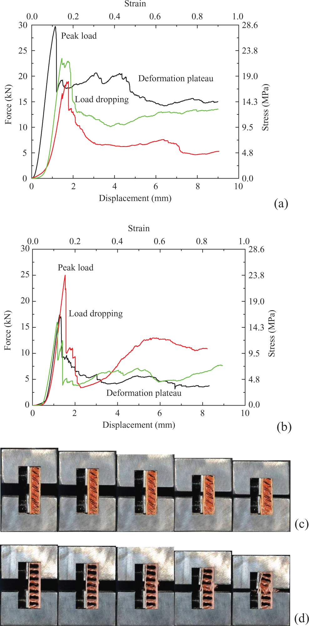
Compression of panels of 10 mm height: (a) deformation curves of weft panels, (b) deformation curves of warp panels, and failure maps of (c) weft and (d) warp panels.
Panels of 80 mm height
Panels of 80 mm height and 100 mm width were weft-compressed, as shown in Figure 10. Controlled by global buckling, the strength varies from 15.0 MPa, 13.5 MPa to 10.8 MPa, much smaller than other shorter weft-compressed panels. The deformation is brittle with an abrupt load drop. Panel of 80 mm height has brittle post-failure mode induced by bending fracture.
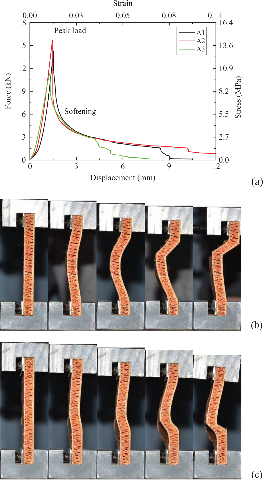
Compression of panels of 80 mm height: (a) deformation curves of weft panels and failure maps of weft panel (b) A1 and (c) A3.
Three-point bending experiments
According to GB/T 1456-2005 standard, 27 to carry out three-point bending experiment on panels with thickness smaller than 10 mm, the span should be greater than 300 mm in order to measure the strength of the skin. ASTM D7249/D7249M-12standard 28 suggests a span-to-thickness ratio of 32 to get facing properties of sandwich constructions by long beam flexure. In this case, the span must be 336 mm. To measure the shear strength of the core, the span is suggested to be 100 mm. According to ASTM C393/C393M-11 standard, 29 to get core shear properties of sandwich constructions by beam flexure, the span is 150 mm, longer than the requirement of GB/T 1456-2005 standard. 27 The width of the panel is suggested to be 60 mm or wider than four times the dimension of the unit cell.
Three-point bending experiments were carried out on CSS44100 test machine at a loading rate lower than 4 mm min−1, as shown in Figures 11 to 13, with span varying from 80 mm, 140 mm to 200 mm. The overhang length is 10 mm, close to the beam thickness. In the tests, all the samples failed due to shear failure of the core. Skin failure was not observed. The longest beam presents a core shear failure mode B, different with collapse mode A of the other two beams, as depicted in Figure 14. Weft beams have much greater load capacities.
Flexural (a) curves and failure modes along (b) weft and (c) warp directions for beams with span of 80 mm.
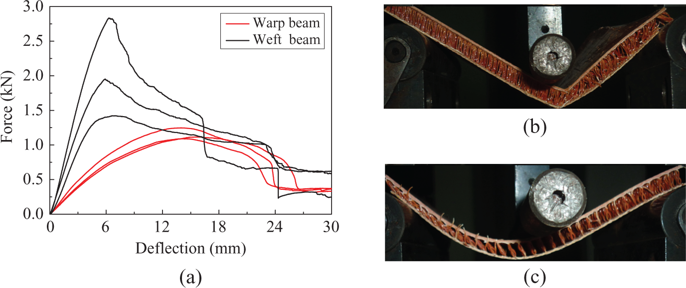
Flexural (a) curves and failure modes along (b) weft and (c) warp directions for beams with span of 140 mm.
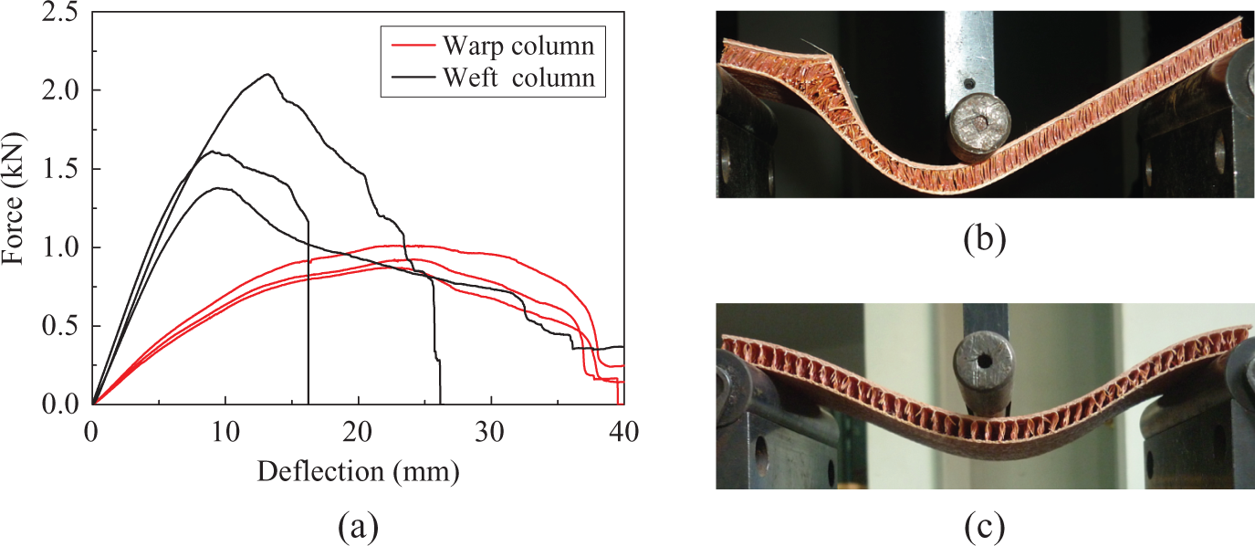
Flexural (a) curves and failure modes along (b) weft and (c) warp directions for beams with span of 200 mm.
Competing collapse modes (a) A and (b) B for core shear of a sandwich beam in three-point bending.
Failure analyses
Failures in edgewise compressions
Initial failure mechanisms
For sandwich panels, skin crushing, skin microbuckling, skin wrinkling, global buckling, and delamination are typical initial failure modes, and global buckling, unstable sandwich disintegration, and stable end crushing are three typical post-failure collapse modes. WTSC panels have integrated woven structure. The skins and the core are linked by fibers, which restrict delamination and unstable sandwich disintegration.
Skin fracture
When the panel is short enough, such as no longer than 10 mm for warp panels and 60 mm for weft panels, the skin will be compressed to fail at material fracture. The value of Pcr is determined by the value of σsc as:

where t and b denote the total skin thickness and the panel width, respectively. Accordingly, compressive strength of the skin is about 110.0 MPa along the weft direction and 90.0 MPa along the warp direction, while its tensile strength is greater, about 130.4 MPa along the weft direction and 112.7 MPa along the warp direction.
Shear fracture
For warp panels, shear resistance of the cores is weak and can be neglected in integral shear failure of 20 mm high warp panels without end steel clamps. So the value of Pcr is determined by the skin shear strength (τsc) as 30 :

According to the tests, the shear strength of the skin along the warp direction is about 45 MPa, about half of the compressive strength.
Global buckling
The Euler buckling load PE is given by the following equation:

where Ef is the modulus of the skin and calculated from the stress–strain curve of compressed panel and listed in Figure 15, c is the thickness of the core, and l is the height of the column. For clamped-end panels, k = 4, while for pin-jointed panels, k = 1. Constant 4.25 is determined by the skin thickness. The core shear buckling load (Ps) is determined by the shear stiffness of the core, namely, 30
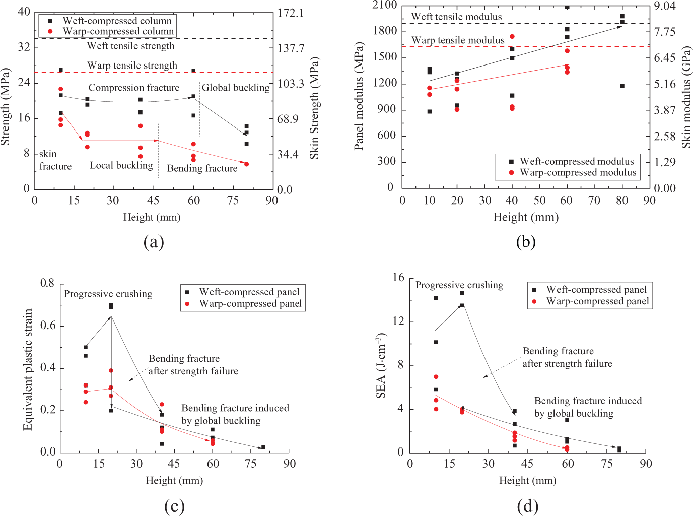
Size dependency and anisotropy of (a) strength, (b) ductility, and (c) SEA of compressed panels.

where Gc is the shear modulus of the core. A combined mode was suggested using the following equation 30 :
Shear modulus of weft panel A3 of 80 mm height is about 14.2 MPa deduced by equation (11), about one-third of the compressive modulus of the woven core. Global compression buckling load should be 45.7 kN deduced by equation (10), much greater than the tested load. So hybrid buckling controls the failure of weft panels of 80 mm length.
Clamped-end warp panels of 60 mm height have hybrid global buckling mode, as shown in Figure 6(e). According to the test and equation (12), shear modulus of the core along the warp direction is about 11.9 MPa in average. For pin-jointed warp panels of 60 mm height, theoretical global buckling load is about 5.4 kN predicted by Euler buckling mode while 4.6 kN predicted by hybrid global buckling. All these two predictions are close to the test data, varying from 5.89 kN, 5.13 kN to 5.09 kN.
For pin-jointed warp panels of 40 mm height, theoretical global buckling load is about 13.2 kN predicted by Euler buckling mode, while hybrid mode would suggest a buckling load of 6.6 kN, which is much closer to the test data, varying from 9.57 kN, 7.79 kN to 6.32 kN.
Local buckling
Local buckling refers to the short wave buckling of the skin. The buckling stress (σfw) in the facesheet is given conservatively by the following equation 30 :

where Ec is the modulus of the core. The critical buckling load is given by the following equation:

According to equations (13) and (14), the critical local buckling load of 80 mm weft panel with pin-jointed ends is 13.7 kN, comparable with the test data, 12.7 kN and 12.4 kN. Global Euler buckling suggests a much smaller buckling load of 7.7 kN. For pin-jointed panels, end buckling is an important failure mode. Theoretical prediction from local buckling also suggests consistent buckling loads with the test data, 15.7 kN and 14.3 kN, of 80 mm high weft panels A1 and A2 in Figure 10.
According to equations (13) and (14), the critical buckling load of 40 mm warp panel with clamped ends should be about 10.0 kN, comparable with the test data, 15.8 MPa, 10.4kN and 8.25 kN, as shown in Figure 7(b) and (f). The critical local buckling load of 20 mm high warp panels, about 10.0 kN, is also comparable with the test data, 13.6 MPa, 13.0 MPa and 10.0 MPa, as shown in Figure 8(b) and (d). It reveals that clamped-end warp panels of 20 mm and 40 mm height initially collapse at local buckling.
Discussion
For weft-compressed panels, skin fracture is the initial failure mode when the height is not more than 60 mm. For panels higher than 60 mm, failure mode will be controlled by global buckling when the ends are clamped and local buckling when the ends are unclamped. For warp-compressed panels of 10 mm height, skin fracture is the initial failure mode. For clamped-end panels of 20 mm and 40 mm height, local buckling dominates the initial failure, while higher warp panels are controlled by global buckling. Warp panels of 20 mm height without end clamps present a shear fracture mode, while longer ones collapse at global buckling.
Post-failure mechanism
Post-failure modes include progressive crushing and bending fracture. The former induces a deformation plateau, while the latter features a sudden drop of load.
Progressive crushing
In progressive crushing mode, the skins have continuous fractures. The post-failure deformation curve has stable stress plateau. Sometimes the stress level of the plateau is even close to the peak load. Progressive crushing endows WTSC panels plastic ductility and efficient energy absorption. Panels no higher than 40 mm collapsed in this mode in the tests, and the initial collapse usually occurred due to compression and shear fracture of the skin. The value of Pcr is determined by compressive strength of the damaged skin σsd using the following equation:

The average failure strength is about 45 MPa for weft panels and 34 MPa for warp panels, both of which are a little smaller than half the strength of the skin.
Bending fracture
Not all the panels whose failure initially controlled by skin strength could be crushed progressively with a stable deformation plateau in the load curves, such as weft panels of 60 mm length. When the skin was cracked, a pin-joint could be formed at the skin of those panels, decreasing the global buckling resistance of the panel. Bending fracture would occur in the panels initially collapsing at global buckling, inducing the stage of softening in post-failure deformation.
Anisotropy and size effect
Anisotropy
Strength and stiffness of WTSC panels have two characteristics, anisotropy and size effect, as shown in Figure 15. In the tests, weft and warp panels have different strength and stiffness, except for panels of 10 mm height, and weft panels are much stronger. The difference in their performance lies in the different core structures. Separated piles in the warp core supply smaller shear resistance than the quasi-continuous piles in the weft core, and it is much easier for warp skins to be bent without the support of continuous core. It can be also noted from Figure 15 that the compressive strength is about two-thirds of the tensile strength. In tension, strength in the weft direction is a little stronger. Skin-woven structures have influences to the performance.
Size effect
According to the tests mentioned above, both strength and stiffness of the panel are related with its size. For weft panels no higher than 60 mm, height has few influences on their strength, which is dependent on the compressive strength of the skins. For weft panels higher than 60 mm, the strength is determined by global buckling and will decrease rapidly. Strength of warp panels gets smaller as the height increases. Compression failure of the skin determines the failure of panels no higher than 40 mm, while global buckling is determinant for panels higher than 40 mm. Modulus gets larger with the increase of the height of the panel till it reaches 40 mm, after then the stiffness would have little change whether in the weft direction or in the warp direction. In extension, the modulus is a little greater.
Ductility
Ductility is related with the post-failure mode and expressed by an equivalent plastic strain (εp), which is defined by the following equation:
where σpeak is the peak stress of the panel and εd is the densification strain, as shown in Figure 2. Symbol εp reflects the level of specific energy absorption (SEA) of the structure. For perfect ductile structures, εp = εd, close to 1, and SEA of the structure is excellent. When εp is close to 0, SEA of the structure is also close to and the structure is brittle.
Only panels of 10 mm and 20 mm height exhibit ductile properties induced by progressive crushing, with εp at the level of 0.5, as shown in Figure 15.
When the height of weft panels is shorter than 40 mm or 60 mm, the panel is ductile in compression. Beyond this height, the panel is brittle. In experiments, strength of these panels was controlled by strength failure, but in post-failure phase, progressive crushing and bending fracture were both observed. The former leads to ductility, as shown in Figures 6(d) and 7(c) and (d). The latter is brittle, as shown in Figures 6(c) and 7(e). Weft panels longer than 60 mm become completely brittle due to failure caused by global buckling and bending fracture, as shown in Figure 10. Columns with great equivalent plastic strain always have large SEA, which was testified by the experiments. SEA of weft panels no higher than 20 mm is greater than 8 J cm−3, while for panels of 40 mm and 60 mm height, it varies from 8 J cm−3 to 2 J cm−3. According to the experiments, panels of 60 mm height have comparable strength to those shorter panels, so the reduction of SEA is caused by brittle deformation induced by post-buckling. Panels of 80 mm height have even smaller SEA due to the same reason.
The failure of warp panels higher than 20 mm is brittle, controlled by global buckling and bending fracture, as shown in Figures 6(e) and 7(f). The equivalent plastic strain is very small, close to the strain corresponding to the peak load. SEA of 10 mm high warp panels is greater than 6 J cm−3. SEA of 20 mm high panels varies from 6.46 J cm−3 to 3.04 J cm−3. When the length of the panel is over 20 mm, its SEA drops abruptly, even smaller than 0.5 J cm−3, which is induced by global buckling and bending fracture.
Failures in three-point bending
Failure modes
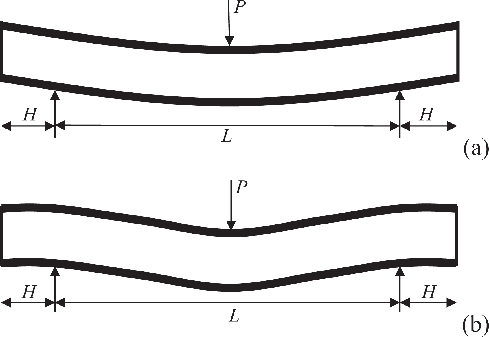
There are two competing shear failure modes in three-point bending experiment. 30 Under bending load, the core is sheared and inclined gradually. With no obvious occurrence of plastic hinges on the skins, the deformation of the skin can be neglected, and the load capacity of panels in three-point bending Pcr is suggested by the following equation 30 :
For collapse mode A,
and for collapse mode B,

where H is the length of overhang beyond the outer supports, L is the span of the beam, and τcs is the shear strength of the core. If the beam fails at bending mode, the load can be predicted by the bending moment (Mcr) as:

where tc and tt denote the thickness of the upper compressed skin and the lower stretched skin, respectively, and σfc is the compressive strength of the WTSC skin. As shown in Figure 16, the peak load has little variation with different spans, so the theoretical load predicted from shear failure mode is consistent with the peak values from the test result, while bending mode is not suit in this case.
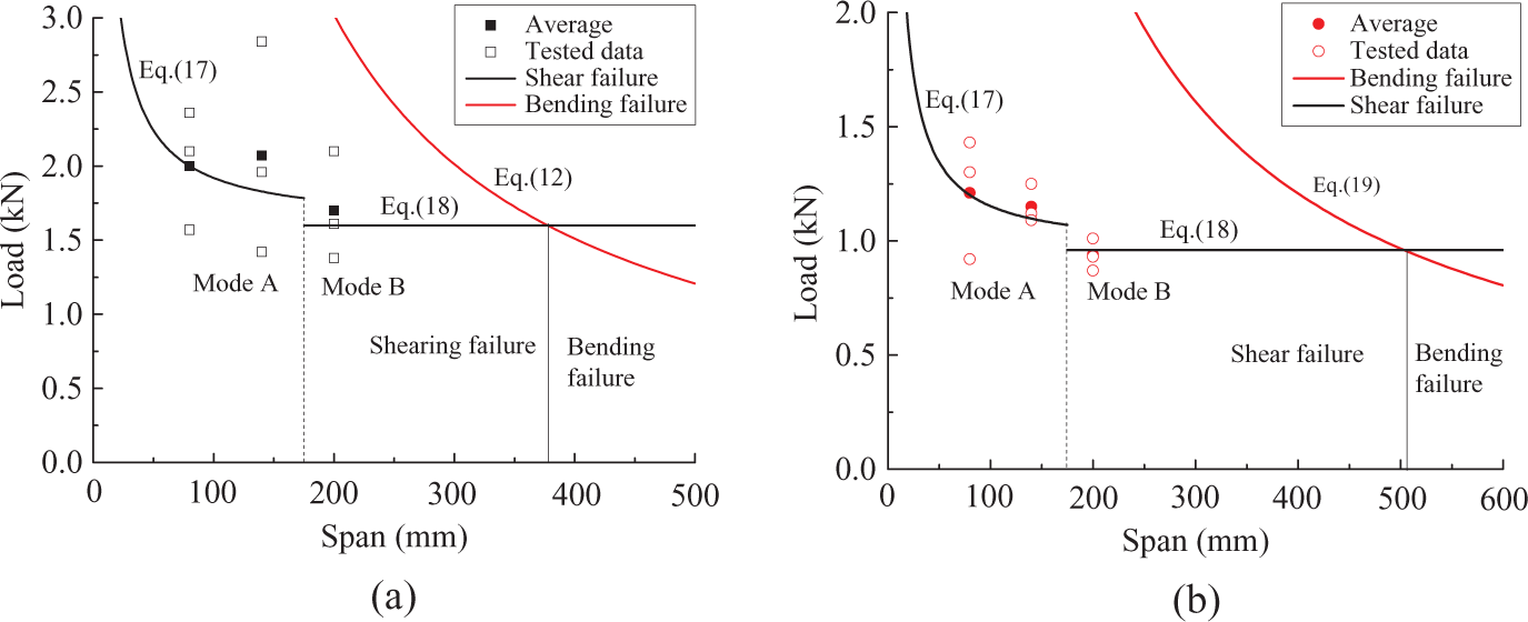
Load capacity and failure modes along (a) warp and (b) weft directions.
Both shear failure modes mentioned above were observed in the experiments. According to equations (17) and (18), the shear strength of WTSC beam is 0.99 MPa and 0.56 MPa along weft and warp directions, respectively, as shown in Figure 17.
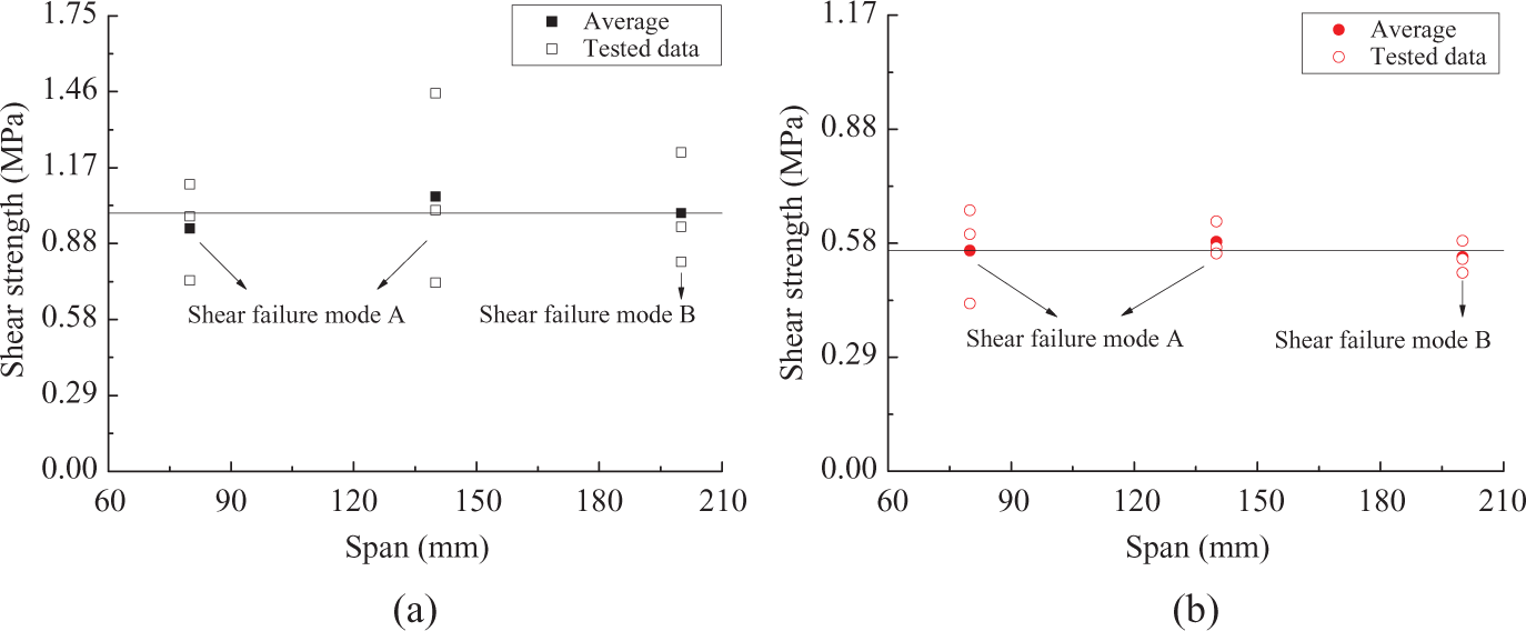
Shear strength along (a) warp and (b) weft directions.
Strength and critical span
According to GB/T 1456-2005 standard, three-point bending experiments were also performed on thinner WTSC panels, with a width of 60 mm, the overhang length of 20 mm, and the span varying from 100 mm, 200 mm to 280 mm. The thickness of WTSC panel is 8.7 mm, with upper skin of 1.2 mm and lower skin of 1.4 mm. Aerial density of the WTSC panel is 4.4 kg m−2. As shown in Figure 18, these WTSC panels have close shear strength along warp and weft directions.
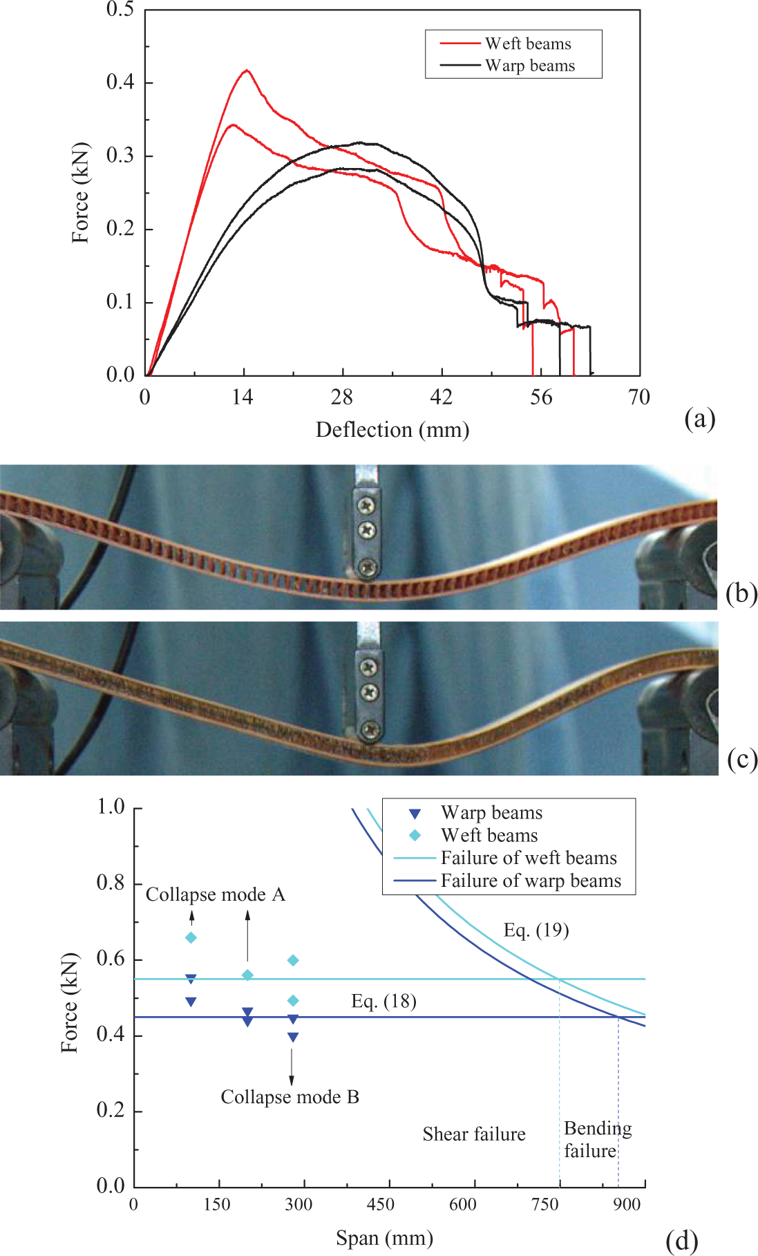
Flexural (a) curves and failure modes along (b) warp and (c) weft direction of thinner WTSC beams with span of 280 mm and (d) corresponding shear strength.
Influence of the span on failure mode is illustrated in Figure 18. Beams longer than 200 mm collapse in mode B, while those shorter than 200 mm collapse in mode A. According to equations (17) and (18), the shear strength of WTSC beam is 0.55 MPa and 0.45 MPa along weft and warp directions, respectively, as shown in Figure 18.
Here, three-point bending experiments only suggest shearing strength of the WTSC beam, which is calculated byequations (17) and (18).
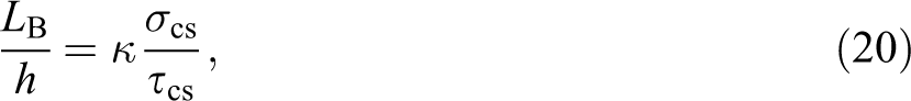
According to the equations (18) and (19), the critical span (LB), which is the turning point between shear failure mode and bending failure mode, is about:
with
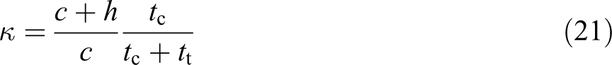
for compressive fracture of the upper skin and
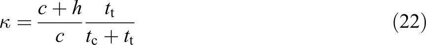
for tensile fracture of the lower skin. Symbol h is the total thickness of the sandwich beam and σcs is the compressive strength of the WTSC panel. When the beam collapses at mode A, the critical value of LA should be given by:

According to the experiments, κ = 1.43 for the thicker WTSC beam. Accordingly, the critical value of LB/h for the tested WTSC beam is larger than 36 and 50. So, to get the bending strength of the skin, the span should be longer than 378 mm and 525 mm along weft and warp directions, respectively. For weaker cores, it is even greater. Here, the critical span exceeds the value suggested by GB/T 1456-2005 standard.
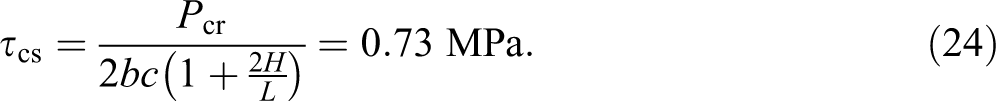
In some cases, the critical span will be smaller than the standard. Fan et al. 18 have reported failure modes of WTSC panels with much smaller thickness in three-point bending. As listed in Table 1 The unstrengthened panel collapsed in bending failure mode, while the strengthened one in shear failure (mode B) at the same span of 100 mm or 120 mm. According to the test results and equation (18), the shear strength of the core is given by the following equation:
Tested data of WTSC panels reported by Fan et al. 18
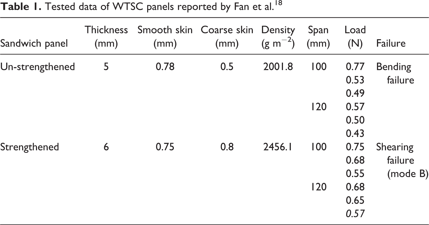
According to testing of unstrengthened panels and equation (19), compressive strength of the skin is given by

As shown in Figure 19, tested data of strengthened panels are well consistent with the values predicted by shear failure mode, while tested data of unstrengthened panels are well consistent with values predicted by bending failure.
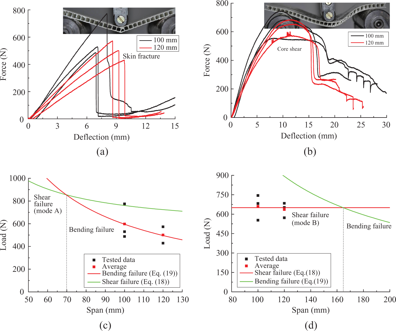
Tested curves of (a) unstrengthened and (b) strengthened WTSC panels reported by Fan et al. 18 and failure predictions of (c) unstrengthened and (d) strengthened WTSC panels. WTSC: woven textile sandwich composite.
The critical span can also be predicted by equations (20) and (23). For unstrengthened panels, κ = 0.92 and LA = 22h−2H = 70 mm. For strengthened panels, κ = 1.14 and LB = 27.6h = 165.6 mm. As shown in Figure 19, the prediction is reasonable. But this critical value of span is much smaller than the one suggested by GB/T 1456-2005 standard.
So, it is concluded that standard span suggested by GB/T 1456-2005 standard cannot be directly applied in the three-point bending experiments of WTSC panels.
Rigidity
Equivalent bending rigidity ((EI)eq) and shearing rigidity ((AG)eq) are determined by the deflection of the sandwich beam (δ) the load (P), and the span as given in the following equation 30 :
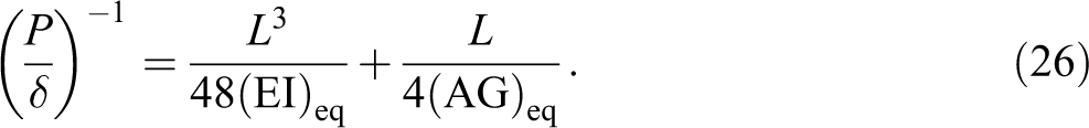
Stiffness (P/δ) varied with span, as shown in Figure 20. Equation (26) suggests consistent predictions with tested data of P/δ. For the thicker WTSC panel, (EI)eq = 3.48 × 10⁷ N mm2 and (AG)eq = 35.7 kN.
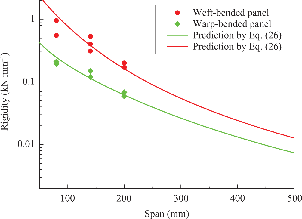
Rigidity of WTSC panels.
Conclusions
The present study focused on the deformation mechanisms and complex failure modes of WTSC panels. Applications of present national test standards in WTSC panels were discussed. Tensile and compressive strength of the skin and compressive and shear strength of the core were calculated. It is concluded that:
In edgewise compression, it is noted that no debonding failure was found. Skin fracture, shear fracture, local buckling, and global buckling controlled the initial failure of panels with different height. Progressive crushing and bending fracture are two post-failure styles. In edgewise compression, strength of weft-loaded WTSC panels keeps unchanged when the height is below 60 mm. Shorter panels have ductile deformation, while the deformation of longer ones are brittle. Heights have great influence on warp-loaded strength. Shorter panels fail at facesheet compression failure, while longer ones fail at local buckling. Present national test standard for ordinary sandwich structures should be adjusted. For weft-loaded panels, the height should below 40 mm or 60 mm to get facesheet compression failure. For warp-loaded panels, the height is hard to select. Perhaps full-scale size-dependent strength and stiffness should be suggested, just as shown in Figure 15. In three-point bending tests, there exist two different failure modes, core shear failure (mode A and mode B) and skin failure. Suggested model can correctly predict the collapse mode and confirm the span for core shear failure and skin failure, respectively. Method to calculate bending strength, core shearing strength, and rigidity were suggested. The test results can serve as reference when adjusting the present method for three-point bending test. The woven textile sandwich composite is anisotropic, with better performance in the weft direction than in the warp direction under either edgewise compression or three-point bending, also better performance in stretching than in compression. So, test standards should suggest specifications to this anisotropy.
These improved methods have been applied to acquire material properties of WTSCs in China Railway High-Speed (CRH) to design wind deflectors, sidewalls, and floor of CRH carbody as well as WTSC-based decorative stone panels.
Footnotes
Declaration of Conflicting Interests
The author(s) declared no potential conflicts of interest with respect to the research, authorship, and/or publication of this article.
Funding
The author(s) disclosed receipt of the following financial support for the research, authorship, and/or publication of this article: Supports from National Natural Science Foundation of China (11172089, 11372095), Program for New Century Excellent Talents in University (NCET-11-0629) and State Key Laboratory of Mechanics and Control of Mechanical Structures (MCMS-0212G01, MCMS-0215G01) are gratefully acknowledged.