
Abstract
The effect of perforated interlayers on the stress wave transmission of multilayered materials was investigated both experimentally and numerically using the Split Hopkinson pressure bar (SHPB) testing. The multilayer combinations consisted of a ceramic face plate and a glass/epoxy backing plate with a laterally constrained low modulus solid or perforated rubber and Teflon interlayer. The perforations on rubber interlayer delayed the stress rise time and reduced the magnitude of the transmitted stress wave at low strains, while the perforations allowed the passage of relatively high transmitted stresses at large strains similar to the solid rubber interlayer. It was concluded that the effect of perforations were somewhat less pronounced in Teflon interlayer configuration, arising from its relatively low Poisson’s ratio. It was finally shown that SHPB testing accompanied with the numerical simulations can be used to analyze the effect of compliant interlayer insertion in the multilayered structures.
Keywords
Introduction
The so-called composite integral armor is a well-known example of the multilayer material systems that are applied for both the structural and functional properties. The composite integral armor is constituted by the sequential layers of two major components: a hard front face ceramic layer of tiles and an energy absorbing continuous composite backing plate. The designing with the layered structures for the integral composite armor of armored vehicles have been reported in several studies to prerequisite the minimum weight of the layers of different acoustic impedances. 1 –4 The dynamic loading response of the layered armor structure can be altered/tailored with the insertion of a low-impedance interlayer material between the ceramic and composite layer. A previous investigation reported that the stress levels decreased, while the degree of stress inhomogeneity increased dramatically in both ceramic and composite layer with the insertion of low-impedance thin continuous rubber interlayer between the ceramic and composite layer. 5 A compliant interlayer provides strong and highly elastic bonding between the ceramic and composite layer, and claimed to enhance the multi-hit capability of the composite armor. 6 The effect of tungsten carbide and silica gel interlayer on the stress wave propagation characteristics of a ceramic matrix composite (CMC)/steel multilayer material system was investigated through the Split Hopkinson pressure bar (SHPB) testing. 7 The protection efficiency of tungsten carbide interlayer armor was reported to be about 36% higher than that the armor without interlayer. Similar experimentations using the SHPB were also performed on a layered structure that consisted of an A3 steel front face layer, an aluminum foam interlayer, and an aluminum backing plate. 8 The results showed that most of the stress wave propagated in the front steel layer was reflected back from the low-modulus aluminum foam interlayer. The use of three interlayers, one in between two ceramic layers, one in between ceramic and composite layer, and one in between two composite plates, provided better protection for the ceramic and composite plates than the baseline configuration composing of one interlayer material between ceramic and composite layers. 9 The use of rubber interlayer between ceramic and composite layers was shown to be very effective in inducing multi-hit capability to the composite armor, 2 while the rubber stiffens very rapidly, leading to high-stress wave transmission to the continuous backing plate. 10 The rubber interlayer stiffening results from the constraint effect of neighboring material to the radial spreading of the rubber. 11 The perforations can reduce the constraint imposed to the interlayer; hence, alter the stress wave propagation.
During the penetration of a multilayered armor system, when the penetrator hits the front surface of the armor, mainly for the first few microseconds, stress wave propagation characteristics of constituent layers dominate the ballistic performance. As the multilayered armor systems are becoming gradually more complex, the stress wave propagation analysis between the constituent layers necessitates both experimental and numerical studies. Several previous studies have investigated the stress wave propagation in multilayer material systems similar to the configurations studied in the current work, notably by Fink and Gama et al. 1 –4 Following these former studies Abrate 12 and Mines 13 reported analytical results for the elastic stress wave propagation in a lightweight structural armor and used Lagrange diagrams to monitor the stress wave propagation. Abrate 12 presented the occurrence of tensile spikes in the ceramic layer and an effective uncoupling of the ceramic layer from the rubber interlayer.
The aim of the current study is to analyze and investigate the effect of the perforated compliant radially constrained interlayers (rubber and Teflon foam) on the stress wave transmission of a multilayered ceramic and composite material system subjected to rapid localized loading. The purpose of confining the interlayer was to more realistically approach the real situation that must be attained in larger size plates of this type of multilayer material system wherein the neighboring material opposes an otherwise free radial deformation of the interlayer. The practical condition possibly lies between the two limits of being completely constrained or unconstrained and consists of partial constraint. Thus, the current study is limited with the wave propagation effects dominated phase.
SHPB can be used as a probe in order to better understand the stress wave propagation characteristics since a known stress wave can easily be applied to the multilayered material system. These known, measured, entry, and exit waves were then reproduced in a finite element model of the multilayer material. It was confirmed that when the numerical data matched the output data from the bars, the numerical model was successfully capturing the stress state within the multilayer material even though the impact velocities and stress levels were somewhat lower than the values observed during the penetration of armor. In testing layered structures using SHPB, one-dimensional stress state is generally assumed. This assumption was proved to be not valid for the multilayer material testing. 14 Therefore, a coupled numerical and experimental study is often needed to be implemented for a comprehensive understanding of the intricate wave propagations in the multilayer structures tested in the SHPB. The finite element analyses of the SHPB tests were performed using the commercial explicit finite element code of LS-DYNA971. The stress/time/location maps were shown and the effects of perforations and impedance mismatch on the stress inhomogeneity were investigated in the current study.
Experimental and numerical
The investigated multilayer system consisted of a 14-mm-thick alumina (‘CoorsTek’ AD-995, Golden, Colorado, USA) ceramic front layer, an 11-mm-thick glass/epoxy composite backing plate, and an interlayer sheet either ethylene propylene diene monomer (EPDM-Shore A 60) rubber (1.5 mm thick) or 2-mm-thick expanded Teflon foam (*PolarchipTM, a trademark of W. L. Gore Inc., Newark, Delaware, USA) with both solid or square/circular perforations. The composite layer, a plain weave S-2 glass fiber woven fabric (5 × 5 and 0.814 kg/m2) SC15 (Applied Poleramic Inc., Benicia, California, USA) epoxy (toughened resin) composite plate, was prepared using a vacuum-assisted resin transfer molding process. 6 The circular perforations and square perforations were performed by punching the interlayer materials. Circular and square hole geometries were selected due to the ease of manufacture. The ratios of the hole diameter to the outer diameter of the interlayer and the edge length of the square to the outer diameter of the interlayer were both tried to be kept close to 0.5. The individual layers (16 mm in diameter) were core drilled and then bonded with epoxy. A steel ring of 6 mm in thickness was used to confine the interlayer laterally during testing. The ceramic layer was always at the impacted side. The SHPB apparatus used in the experiments consisted of 19 mm Inconel 718 bars with the striker bar 356 mm long, incident bar 3450 mm long and transmitter bar 1850 mm long. The details of the used SHPB test setup and the data reduction are given elsewhere. 15 The tests were performed at a striker velocity of 20.5 m/s.
A full SHPB test model (no symmetry definitions) is shown in Figure 1(a). The model consists of the incident and transmitter bar and the specimen and confinement ring, and it uses a shorter bar length of 1524 mm in order to reduce the computational time. 16 The use of shorter bar length does not affect the stress wave shapes and amplitudes. The elastic wave velocity of Inconel bars was 5003 m/s. In the numerical simulations, the experimentally determined incident bar wave at 20.5 m/s striker bar velocity was used as an input to the face of the incident bar and the numerical stress waves on the bars were determined at the locations of the strain gages on the incident and transmitter bars of the SHPB setup. The cross-sectional views of solid and perforated interlayers are shown in Figure 1(b) to (d). The circular perforation is 7 mm in diameter (Figure 1(c)) and the square perforation is 7 mm in edge length (Figure 1(d)).
Finite element model used in the study: (a) Hopkinson bars and multilayer specimen between them (red cylinder is incident bar, blue cylinder is transmitted bar, transparent hollow cylinder is confinement), cross-sectional views of numerical models of (b) solid, (c) circular hole, and (d) square hole interlayers.
The bars and specimen were modeled using eight-node solid elements: 300 elements in the cross section of the specimen (10 elements across the radius) and 400 solid elements through the length of the bars. The mesh sensitivity of the SHPB model under a known stress pulse was checked by varying the number of elements along the length of both specimen and bars, while varying the number of elements in the cross section as well. Calculations were done for several mesh densities. Shapes, magnitudes, and the oscillations in the experimentally determined signals were cross-checked with those of numerically obtained. Based on these trials, the acceptable minimum number of elements was determined and the meshes consisting of these elements were used throughout the current study. Mesh biasing along the bar axis was applied in order to refine the meshes at the contact interfaces. Surface to surface contact was defined between the incident/transmitter bar ends and ceramic/composite ends. Since the interfaces between interlayer and ceramic and composite were not perfectly bonded, that is, confined frictionally, no interface delamination occurred in the simulations. Eroding nodes to surface contact definition was used for the contact between the interlayer and ceramic/composite ends. Lateral confinement of the interlayer was modeled by defining a rigid circular disk having a thickness of 6 mm, the same dimensions used in experiments. In many anticipated applications the interlayer material may be imposed to the lateral constraints by the surrounding material itself, which may affect the through thickness stresses. The simulations performed here merely considered the fully constrained case, which was also tested experimentally. Static and dynamic friction coefficients of 0.3 and 0.2 were used for the contact definitions, respectively. In the model, the surfaces of bar ends were assumed to be perfectly flat and the bars were assumed to be deforming elastically during the simulations. The deformation of the ceramic and composite layer and EPDM rubber, Teflon interlayers were sequentially modeled using the elastic, 17 orthotropic elastic, 17 Ogden, 18 and the crushable foam material models. 17 The Inconel bars were modeled with an isotropic elastic material model. Material properties used in the finite element analyses are given in Table 1.
Material model properties used in numerical models.
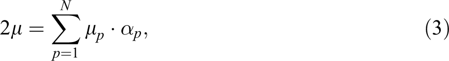
Rubber was modeled with the Ogden material model 18 and is considered to be fully incompressible, since the bulk modulus greatly exceeds the shear modulus in magnitude. In order to model the rubber a hydrostatic work term is included in the strain energy functional as a function of the relative volume. In the Ogden material model, the strain energy density can be expressed in terms of the principal stretches λ α, where α = 1, 2, 3, as
where N, μp , and αp are material constants. Under the assumption of incompressibility, it can be rewritten as
In general, the shear modulus results from
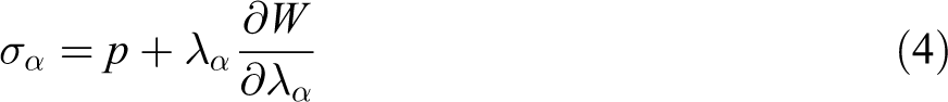
with N = 3 and by fitting the material properties, the material behavior of EPDM can be described accurately. For particular values of material constants, the Ogden model will reduce to either the Neo–Hookean solid (N = 1, α = 2) or the Mooney–Rivlin material (N = 2, α 1 = 2, α 2 = −2). Using the Ogden material model, the three principal values of the Cauchy stresses can now be computed as
Expanded Teflon is modeled with the crushable foam material model 17 and this material model is dedicated to modeling crushable foam with optional damping and tension cutoff. Unloading is fully elastic. Tension is treated as elastic-perfectly-plastic at the tension cutoff value. For determining the constants of the Ogden and crushable foam models, the stress versus strain curve is used as input and the least squares fit to the experimental data is performed during the initialization phase. In the Ogden model, rate effects were taken into account through linear viscoelasticity by a convolution integral.
Results and discussion
The large deformation of the rubber necessitates the use of finer mesh size; therefore, the initial modeling of the SHPB testing of the configuration with EPDM rubber interlayer was performed using different element sizes of 0.9, 0.6, and 0.45 mm. Based on the accuracy and the duration of the solution, an element size of 0.6 mm was selected. The experimental and numerical incident, reflected and transmitted stress–time graphs of the SHPB tests at 20.5 m/s striker bar velocity in the configurations with solid, circular, and square-hole rubber interlayers are shown in Figure 2(a) to (c), respectively. Although the numerical and experimental transmitted peak stresses of the solid rubber interlayer are similar, the numerical reflected peak stress is higher than experimental reflected peak stress as seen in Figure 2(a). The experimental and numerical reflected peak stresses of both circular and square-hole interlayer configurations are very much similar, while the numerical transmitted peak stresses of both configurations are slightly higher than the experimental transmitted peak stress, depicted in Figure 2(b) and (c). Figure 3(a) to (c) shows sequentially the experimental and numerical SHPB test stress–time histories of solid, circular, and square perforated Teflon interlayer configurations. The numerical and experimental reflected peak stresses and the profiles of the reflected and transmitted stresses are very much similar, while, the numerical simulation transmitted peak stress values are slightly higher than those of the experiments. Despite the variations in the stress values, the numerical and experimental stress values of the investigated configurations are presumed to show acceptable agreements between each other, when considering the experimental errors in each test and the small variations between the geometry and microstructure of the individual test samples.
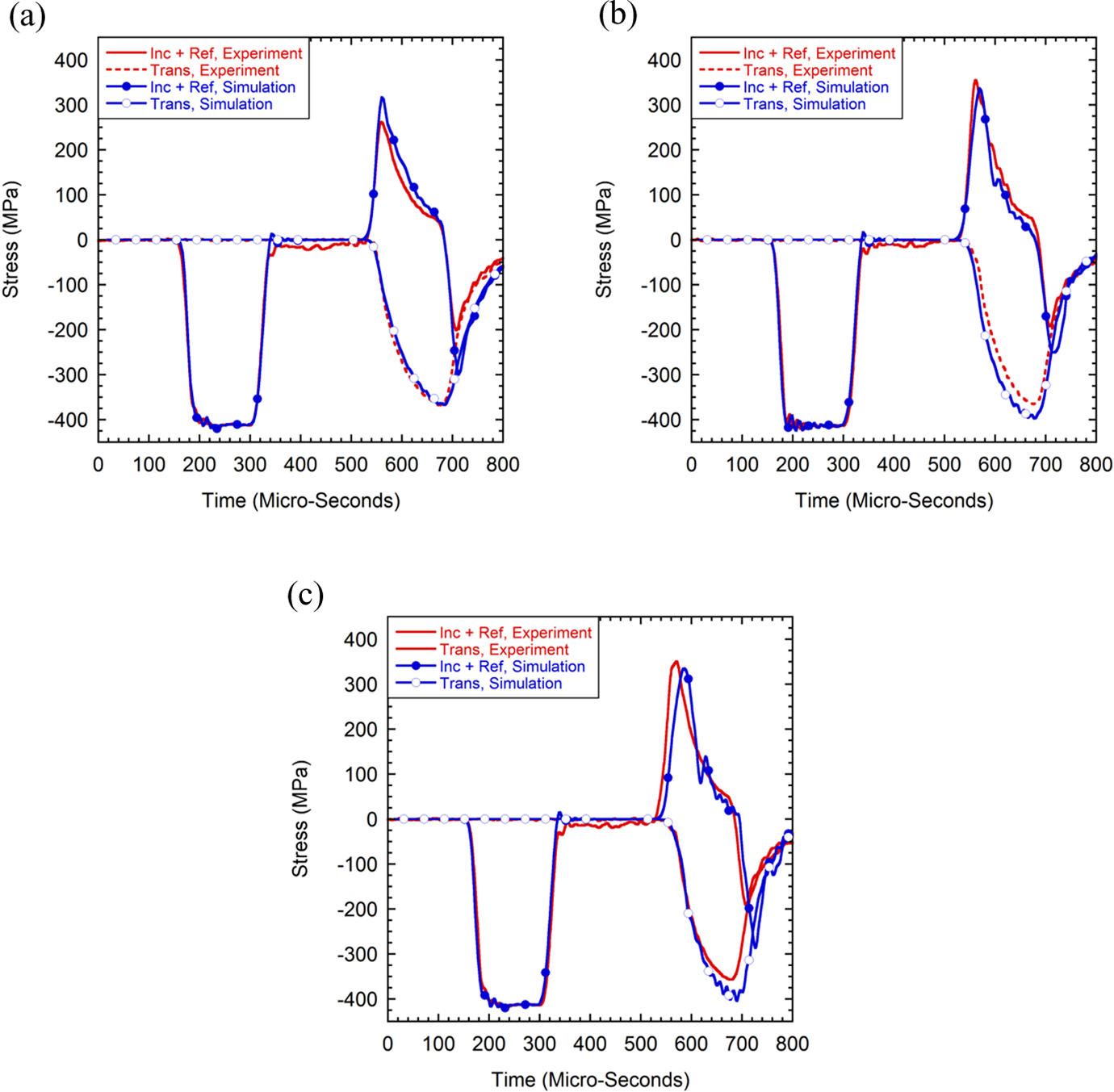
Stress–time histories of results of specimens having (a) solid rubber, (b) circular hole rubber, and (c) square hole rubber interlayer.
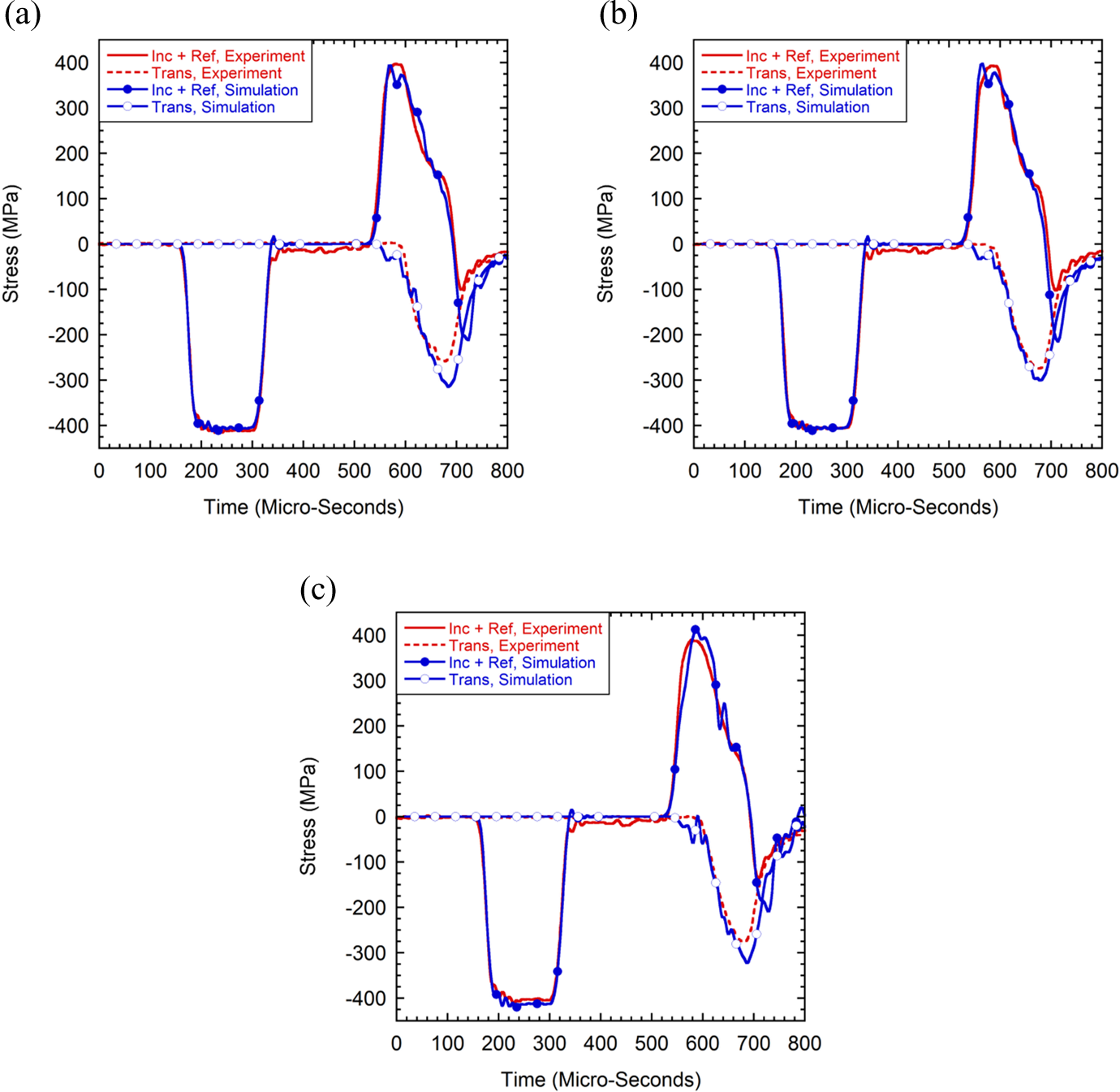
Stress–time histories of results of specimens having (a) solid Teflon, (b) circular hole Teflon, and (c) square hole Teflon interlayer.
In order to determine the effect of rubber and Teflon interlayer on stress rise time, the experimental and numerical transmitted stress–time graphs of three configurations, solid, circular, and square hole rubber and Teflon interlayer, are drawn together in Figure 4(a) and (b), respectively. In the same graphs, only one reflected stress is drawn to identify the delays in stress rise times since the reflected stresses of the different configurations begin to increase from the same point on the time scale. The delays are determined at an offset stress of 100 MPa as seen in Figure 4(a) and (b). Since the time steps of the SHPB experiments and simulations were selected as 1 µs, the results of the stress rise time values may show ±10% alterations. The solid rubber interlayer results in approximately 15 µs delay in experimental and numerical transmitted stress rise time (Figure 4(a) and (b)). The delay is partly arisen from the wave propagation in the sample and partly from the compliant interlayer. Both circular and square perforations in rubber interface result in stress rise time delays up to approximately 20 µs, while the time delay in square perforated interlayer is higher than circular perforated interlayer, as seen in Figure 4(a) and (b). EPDM rubber is assumed to be nearly incompressible and the constraining prevents the radial deformation of the rubber, resulting in the increased stress values in the transmitted wave. In perforated rubber interlayer, however, the perforated region allowed the material to deform freely along the radial direction, leading to reductions in the transmitted stress levels and delays in the stress wave transmission. No significant effect of perforations in Teflon layer on the experimental and numerical transmitted stress rise time is seen Figure 4(a) and (b), while all three configurations, solid, circular, and square perforated interlayer result in same relative time delay as compared to rubber interlayer, approximately 45 µs. The highest peak transmitted stress is observed in square hole Teflon interlayer, which is approximately 33% smaller than that of square hole rubber configuration that has minimum peak transmitted wave among other rubber interlayer configurations. As the Teflon interlayer has a Poisson’s ratio that is almost half that of rubber, inherited from its porous structure, the constraint effect of the surrounding material is expected to be substantially lower than that of rubber interlayer. This expectedly results in relatively small increase in stress time delays with the insertion of circular and square perforations in Teflon interlayer, which is in accord with the experimental and numerical simulation results. The constraint effect increases the stiffness of the rubber interlayer more quickly than that of the Teflon interlayer, leading to increased transmitted stresses to the backing plate. The stress wave propagation in aluminum foam interlayer-containing armor was investigated previously. 2 Compliant aluminum foam interlayer was shown to result in reduction in the amplitude of the stress pulse transferred to the backing plate and time delay in stress transfer to the composite backing plate. These are beneficial in delaying the micro-damage mechanism; hence, resulting in an increase in the ballistic performance of armor system.
Transmitted stress–time histories of the rubber and Teflon interlayer: (a) experiment and (b) numerical.
Figure 5(a) to (d) shows the numerical displacement histories of the interlayer materials. For the solid rubber interlayer configuration, the front and the back surfaces of the interlayer almost displaced with the same pattern due to the incompressible nature of the rubber, Figure 5(a). For the circular hole rubber configuration during the course of compression material flowed radially and this allowed relative displacement differences in the front and back surfaces of the interlayer, Figure 5(b). However, the displacement histories of the Teflon interlayer did not change significantly due to the existence of perforation, Figure 5(c) and (d).
Numerical displacement histories of interlayers: (a) solid rubber, (b) circular hole rubber, (c) solid Teflon, and (d) circular hole Teflon interlayers.
Figure 6(a) and (b) shows the hydrostatic stress histories of the three different points located along the midsection of the interlayers for three different radial locations: 3.5, 5.75, and 8 mm from the centerline. For the case of solid rubber, the hydrostatic stress distribution is almost independent of radial location, while the hydrostatic stress at the inner radius surface is significantly reduced as compared with the hydrostatic stresses at the distance of 5.75 and 8 mm in circular hole rubber. For the Teflon interlayer, the existence of inner hole caused an increase in the hydrostatic stress values as compared to the solid Teflon interlayer configuration. This might arise due to the fact that the inner hole allowed the Teflon material being deformed to higher levels, Figure 5(c) and (d). Since the Poisson’s ratio of the Teflon material is significantly lower than that of rubber, there was less amount of radial flow tendency and that resulted in higher values of hydrostatic stress close to the centerline of the specimen.
Hydrostatic stress histories of three different points along the midsection of (a) rubber and (b) Teflon interlayers.
Figure 7(a) and (b) shows the numerical stress–distance–time maps of the solid rubber and solid Teflon interlayer configurations, respectively. The peak stress in rubber interlayer configuration is highest at the front of the ceramic layer; it decreases through the rubber interlayer and increases in the composite layer (Figure 7(a)). A more uniform peak stress distribution along three layers of the test sample is seen in Teflon interlayer configuration, except the front of the ceramic layer and back of the composite layer (Figure 7(b)). Insertion perforation in the rubber interlayer increases the peak stress in the ceramic layer, while it decreases the peak stress in the composite layer as shown in Figure 7(c). Although, perforation in Teflon layer increases both the peak stresses in ceramic and composite layer, it induces a more uniform peak stress distribution along test sample as shown in Figure 7(d). As seen from the results, existence of hole in the interlayer can be used to control the stress wave transfer to the composite backing plate. However, this controlling effect can only be dominant during the initial stages of the compression since as the deformation continues the inner surfaces of the hole touch themselves and that causes significant amount of increase in the acoustic impedance values, thus much of the wave is transmitted through the interlayer. This effect is more apparent in the case of rubber due to the hyperelastic nature. A previous study on the investigation of high-velocity impact on a multilayered material system similar to the case investigated in the current study by Mahfuz et al. 19 showed that the interlayer caused significant alterations in the stress wave propagation characteristics and there were significant amounts of tensile stress values reported at the interface, which might cause delamination between the interlayer and the contacting armor constituents. However, in the current study there were no significant tensile spikes in the stress wave histories observed due to the much longer compressive stress pulse introduced through the incident bar as opposite to the short time length compressive pulse generated by the hit of fragment simulating projectile in the work by Mahfuz et al. 19
Stress–distance–time maps of multilayer materials having solid or perforated interlayers: (a) solid rubber, (b) solid Teflon, (c) square hole rubber, and (d) square hole Teflon interlayer.
The numerical deformation pictures of circular square perforated rubber and Teflon interlayers are shown comparatively in Figure 8(a) to (d) , respectively, at the interval of 150 µs between consecutive frames. Comparing Figure 8(a) and (b) and Figure 8(c) and (d), the effect of Poisson’s ratio on the deformation behaviors of interlayer materials can be seen clearly. At the same deformation time, the rubber interlayer shows a more extensive deformation (elastic) than the Teflon interlayer through the perforated areas. As the stress decreases on the interlayers, the rubber starts to recover the initial dimensions gradually, an effect of the viscoelastic deformation behavior of rubber (Figure 8(a) and (c)), while Teflon shows permanent deformation, simply arisen plastic deformation of the Teflon (Figure 8(b) and (d)). Experimental and numerical deformed pictures of square perforated Teflon interlayer specimen after the test are shown in Figure 9 for comparison. Although, the experimental and numerical deformed shapes of the Teflon interlayer are pretty much similar, the experimental Teflon interlayer deformation along the diagonal axis is seen to be slightly higher than numerical deformation. This is attributed to multiple reloading of the sample during SHPB testing, which presumably enlarge deformed zone progressively.
Deformation histories of interlayer materials with 150 µs intervals: (a) circular hole rubber, (b) circular hole Teflon, (c) square hole rubber, and (d) square hole Teflon.
Comparison of experimental and numerical results of square hole Teflon interlayer.
Present results clearly indicated that SHPB testing accompanied with the numerical simulations can be used to analyze the effect of compliant interlayer insertion in the multilayered structures. The experimental and numerical results show that perforations in rubber interlayer of high Poisson’s ratio are effective in delaying the transmitted stress rise time to the back composite, while no significant effect of perforations on the transmitted stress rise time is found in the Teflon interlayer with relatively lower Poisson’s ratio, at the studied striker bar velocity. In the rubber interlayer, the perforations allow the rubber to deform without constraint at lower stresses, leading to reduced stress transmission to the back composite. At high stresses, however, the perforated interlayer transmits relatively high stresses similar to the solid rubber interlayer. These effects are less pronounced in Teflon interlayer. The stress transmission to the backing composite and the stress time delay depend on the area of non-perforated and the thickness of the interlayer. The thicker and the lower non-perforated area of the interlayer, the longer is the stress time delay and the lower the stress passage to backing plate. Previously it was shown that the ballistic performance of ceramic/metal armor increased with increasing the thickness of the adhesive layer. 20 The thick interlayer reduced the damage/fragmentation of the backing plate. Furthermore, the reduced stress transmission to the backing plate with the insertion of a low acoustic impedance in silica gel interlayer in a CMC/Rolled Homogenous Armor (RHA) multilayered structure was also shown in the work by Wang et al. 7
Noting that an excessive deformation of the rubber interlayer would finally shift the interlayer deformation from unconstrained to constrained condition, the perforated interlayer area that allows the rubber extension without constraint during the course of the deformation should be calculated. In designing armor structures with perforated interlayers, therefore, an optimized perforated interlayer area and thickness of the interlayer allowing the delays in the stress rise time with the passage of lower stresses to backing composite should be determined. This will be addressed in future by testing the armor plates of the perforated interlayers using the armor piercing projectiles. The present study focused on the wave propagation in multilayer structure at low stress levels. The wave propagation may be however quite different at very high stress levels (i.e. the levels of the fracture of ceramic layer). This should be addressed in a separate study.
Conclusions
The effect of perforated rubber and Teflon interlayer on the stress wave transmission of multilayer ceramic-composite material was experimentally and numerically determined using SHPB tests. Experimental and numerical results showed that perforations on rubber interlayers delayed the stress rise time and reduced the magnitude of the transmitted stress at low strains. At large strains, the perforated rubber interlayer allowed the passage of transmitted stresses similar to the solid rubber interlayer. These effects were less pronounced in Teflon interlayer. Because rubber has a quite high Poisson’s ratio, punching perforations allows the material to deform easily in directions perpendicular to its loading axis. The opposite is valid for Teflon interlayers because of its lower Poisson’s ratio. It was finally shown that SHPB testing accompanied with the numerical simulations can be used to analyze the effect of compliant interlayer insertion in the multilayered structures.
Footnotes
Acknowledgment
The authors would like to thank Prof. Dr Ian W. Hall and Prof. Dr Mustafa Güden for their contributions.
Declaration of Conflicting Interests
The author(s) declared no potential conflicts of interest with respect to the research, authorship, and/or publication of this article.
Funding
The author(s) received no financial support for the research, authorship, and/or publication of this article.