
Abstract
In this work, the wear behavior of cross-linked ultra-high-molecular weight polyethylene (UHMWPE) is discussed. The UHMWPE specimens are molded through injection molding techniques by varying the parameters of melting temperature (MT). The cross linking of UHMWPE was carried out by iridium 192 isotopes, where the specimen received 25 kGy energy. The wear tests were conducted on a hip joint simulator that was designed and fabricated in the laboratory. The contact loads are varied from 50 N to 100 N. The study revealed that MT has influenced the hardness and wear properties such as coefficient of friction and wear rate, respectively. γ-Irradiated UHMWPE has better wear and friction resistances than unirradiated UHMWPE. The worn out surfaces were examined with the help of scanning electron microscope, and it revealed the presence of wear mechanisms such as ironing, scratching, ploughing, plastic deformation, and fatigue wear.
Introduction
Biomaterials are nonviable materials used in biomedical applications ranging widely from orthopedic implants, catheters, lenses, and artificial blood vessels to stents and in vivo devices such as pacemakers. 1 These materials intended to interact with biological systems and cover several classes of materials such as metallic, ceramic, and polymeric materials. Medical implants are products that have to satisfy functionality demands defined by the human body as working environment. 2 Polymers are seeing increasing use inside the human body. One of the most significant current discussions in orthopedic is the total hip replacement, and there is increasing trend for replacing degraded and destroyed biomaterials. 3 Ultra high-molecular weight polyethylene (UHMWPE) has been used as a load bearing material in artificial joints for four decades. There has been considerable interest in the study of wear behavior of UHMWPE. 4 The growing demand for UHMWPE as a bearing material for joint replacement has lead to active research in the development and understanding of its properties. 5 However, such implants have a limited pain-free lifetime due to the results of UHMWPE wear particulate being deposited in tissues surrounding the joint. The anatomical reaction to this particulate is termed osteolysis, which results in gradual loss of the bone tissue surrounding the stem of the implant eventually leading to implant loosening. 6
UHMWPE has been used in medical applications such as hip joint cups, the gliding parts of knee, and shoulder and elbow joint replacements due to its excellent mechanical properties such as exceptional impact resistance, high strength, low creep, low coefficient of friction (COF), abrasion resistance, and biocompatibility. 7 In recent years, the use of UHMWPE for total hip replacement has increased significantly as a consequence of good mechanical and tribological properties. It shows low COF and excellent chemical stability when it is in contact with sinovial fluids. In order to improve the surgical practices and postoperative rehabilitation, it is necessary to conduct test in joint simulators. 8 Injection molding is one of the successful production techniques to manufacture UHMWPE components. 9,10
Wear of UHMWPE bearing surfaces contributes to the particulate debris burden that eventually leads to periprosthetic osteolysis in total joints. Radiation cross linking of UHMWPE has been used to decrease wear successfully in vitro. 11 Zhang et al. have investigated that the friction and wear behavior of argon plasma-treated pure UHMWPE material was due to high cross link that caused less adhesive force interaction between the materials, thereby obtaining a lower value of COF. 12 Di et al. have studied that the effect of γ-irradiation on the tribological behavior of high-density polyethylene (HDPE) filled with UHMWPE. The study shows that the interfacial cross linking that was formed due to irradiation has degraded the UHMWPE molecular chains but the addition of HDPE significantly increases the wear resistance (WR) of UHMWPE composites. 13 Muratoglu et al. showed that the mechanism of improvement in the WR by increasing the cross-link density primarily depends on the decreased conformational segmental mobility of the cross-linked polymeric chains. Hence, this leads to a significant reduction in the surface deformation and orientation, which are the primary precursors of wear particle generation. 14
The aim of the study is to investigate the influence of irradiation effect on wear behavior of UHMWPE. Therefore, two materials are used, one with unirradiated UHMWPE and another with γ-irradiated UHMWPE (γ-UHMWPE). The femoral heads and acetabular cups are manufactured through injection molding technique and their tribological properties are tested in hip joint simulator. Different MTs are used for the injection-molded UHMWPE specimens and varying contact loads are used to study the wear behavior of the specimens. The COF and wear rate are evaluated through this test. The worn out morphologies are studied with the help of scanning electron microscopy (SEM).
Materials and methods
Materials and specimen preparation
In this study, an injection grade UHMWPE obtained in powder form from Spectra Polymers (model GUR5113; Coimbatore, India) is used. It has a tensile strength of 17 MPa and a bulk density of 0.93 g/cm3. Before injection molding, the powder is preheated for 2 h at 100°C in an electric oven to remove the excess moisture content. A mold die design made up of mild steel was used to prepare the wear test specimens. The test specimen relevant to hip joint wear simulator and their dimensions is shown in Figure 1.
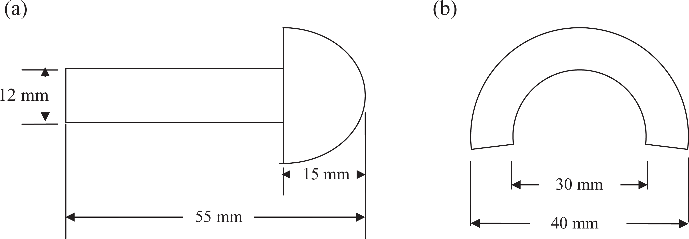
Representation of (a) femoral head and (b) acetabular cup.
Wear specimens are prepared on a Texas injection molding machine (ROBOSHOT S-2000i 50A, FANUC India Pvt Ltd, Bangalore). The machine can offer a maximum clamping force of 30 tons, a maximum injection velocity of 330 mm/s, the screw diameter is 22 mm, and the maximum injection volume is 29 × 103 mm3. Three MTs (260, 280, and 300°C) were used as injection molding parameters, where the injection velocity and compaction time were maintained at 125 mm/s and 60 s, respectively. After the injection molding process, all the specimens were machined to remove burrs and excess materials.
Two different types of materials were used in this study, one with unirradiated UHMWPE and another with γ--UHMWPE. UHMWPE specimens were irradiated at 28°C using iridium 192 isotopes, where the specimens received a final dose of 25 kGy and the magnitude of dosage is measured by a dosimeter. The hardness was measured using a Vickers hardness tester (Shimadzu, Singapore, Singapore), which has a square-based pyramid diamond indenter with an angle of 136° between the opposite faces at the vertex. The test conditions have been maintained at a load of 9.8 N for 15 s at room temperature.
Figure 2 shows the experimental setup of wear tests that conducted on a hip joint simulator designed and fabricated based on the experimental procedure of Ge et al.
15
The contact loads were varied from 50 N to 100 N. The revolution frequency and the test duration were maintained at 1 Hz and 10,000 rotation cycles, respectively. The tests were performed synchronously on the hip joint wear simulator station with bovine serum as a lubricant, which was procured from M/s Subra Chemicals (Pondicherry, India). After the tests were conducted, the specimens were dried in an oven at 100°C for 1 h to undergo weight loss measurements. The friction force is measured using load cell and COF can be calculated using the following equation: Assembly of hip simulator. (1) Load cell, (2) vertical rod, (3) cup holder, (4) acetabular cup, (5) angel plate, (6) rotating table, (7) shaft pulley, (8) rotating table shaft, (9) V belt, (10) motor, (11) motor pulley, (12) femoral head, (13) strain gauge, and (14) load.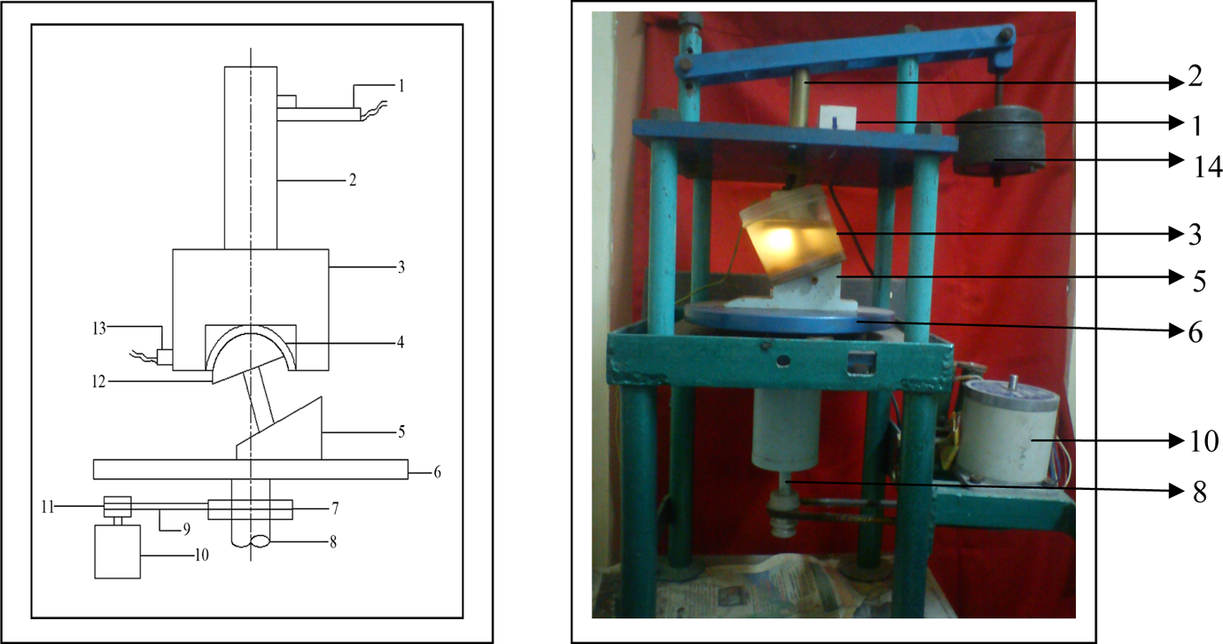
where μ is the COF, H is the horizontal (or) friction force, and F is the vertical (or) normal force. The wear volume loss is calculated and finally wear rate of the specimen is calculated using the ratio of wear volume loss to sliding distance. The worn out samples were examined by scanning electron microscope (JEOL Corp., Akishima, Japan) and the different wear mechanisms were identified.
Results and discussion
Hardness behavior
Microhardness is considered as one of the important properties of materials, which acts as an indicator for the WR of polymers. The microhardness for UHMWPE and γ-UHMWPE with different MTs is shown in Figure 3. It is observed that the microhardness is maximum for both unirradiated and γ-irradiated UHMWPE when the MT was maintained at 280°C. Also, it can be seen that γ-UHMWPE has more hardness than that of unirradiated UHMWPE.
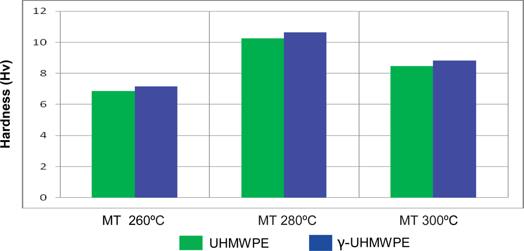
Effect of different MTs on hardness. MTs: melting temperatures.
The minimum hardness is obtained at an MT of 260°C. Figure 4 shows the micrographs of unworn UHMWPE and γ-UHMWPE. It is observed large number of cracks and poor bonding in the case of UHMWPE, whereas sufficient bonding and few cracks are observed in γ-UHMWPE. The above statements are well correlated with the reference of Kanaga Karuppiah et al., 16 as the increase in crystallinity has lead to increase in hardness for the specimens corresponding to MT of 280°C.
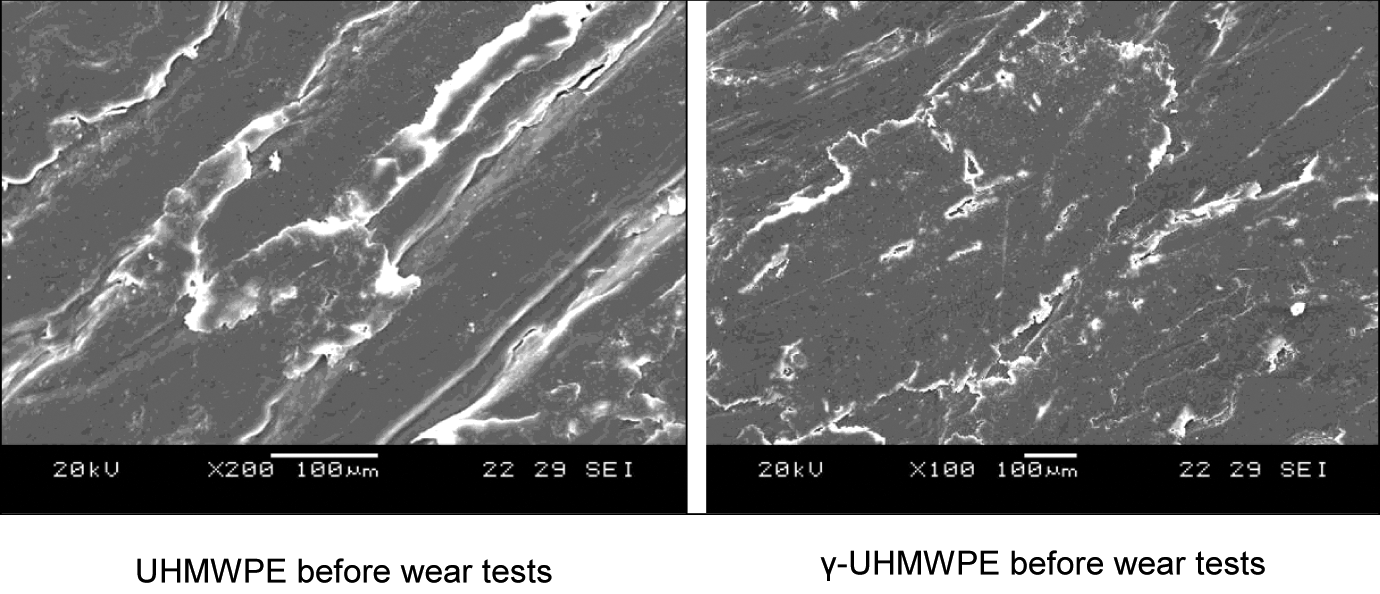
SEM images of unworn specimens. SEM: scanning electron microscopy.
Friction behavior
Figure 5 shows the influence of various MTs, γ-irradiation and contact load on COF. As far as the MT is concerned, the lowest COF increases with increase in contact load. Also it is clearly seen that the COF of γ-UHMWPE is found to be slightly lesser than that of UHMWPE. The maximum COF for UHMWPE and γ-UHMWPE are 0.160 and 0.149, respectively, whereas the minimum COF for UHMWPE and γ-UHMWPE are 0.13 and 0.12, respectively. It is also observed that UHMWPE and γ-UHMWPE specimens corresponding to MT of 280°C have minimum COF. As the UHMWPE is a viscoelastic material, its deformation under contact will also exhibit viscoelastic behavior. Due to critical surface energy of the UHMWPE, the COF increases with increase in contact load. 17 Also the temperature raised at the surface asperities of contacting surfaces of UHMWPE could deform molecular chains of polymer. 18 In general, γ-UHMWPE has better frictional resistance than UHMWPE as there is formation of more transfer films on γ-UHMWPE. 19
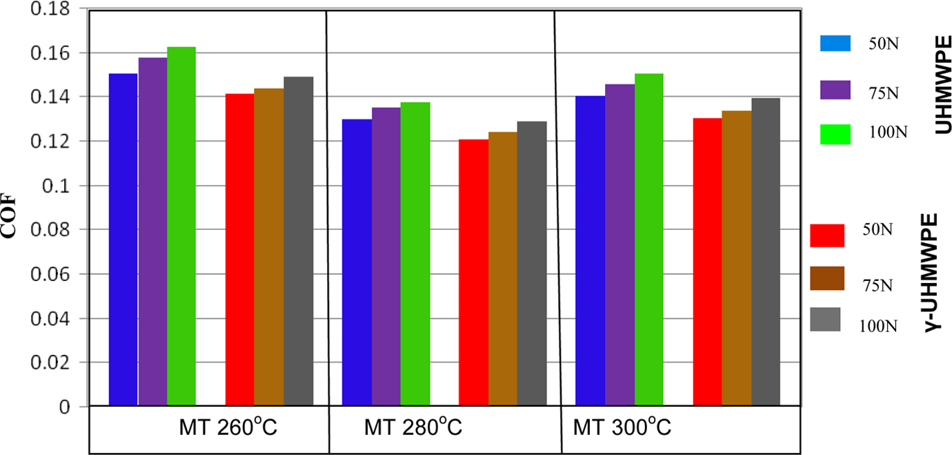
Effect of different MTs and load on COF. MTs: melting temperatures; COF: coefficient of friction.
Wear behavior
Figure 6 shows the variation in wear rate with respect to MT and contact load for both UHMWPE and γ-UHMWPE materials. Both UHMWPE and γ-UHMWPE specimens corresponding to MT of 260°C have highest WR, whereas the specimens corresponding to MT of 280°C have lowest WR. At MT corresponding to γ-UHMWPE has a minimum WR of 0.02 mm3/min when compared to UHMWPE with 0.018 mm3/min.
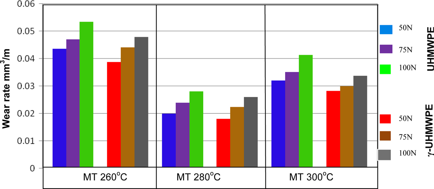
Effect of different MTs and load on wear rate in cubic millimeter per meter. MTs: melting temperatures.
The decreasing wear rate and COF for γ-UHMWPE are attributed to the formation of fine wear particles, whereas in the case of UHMWPE, it is observed as a plate-like form. Figure 7 shows the micrographs of worn out surface through SEM. It shows frozen layers for UHMWPE when compared to that of γ-UHMWPE. These frozen layers are formed at different thicknesses for different MT conditions, which change the surface property, melting density, or viscosity, and a higher temperature gradient occurred near the mold wall due to the heat transfer effect. 20
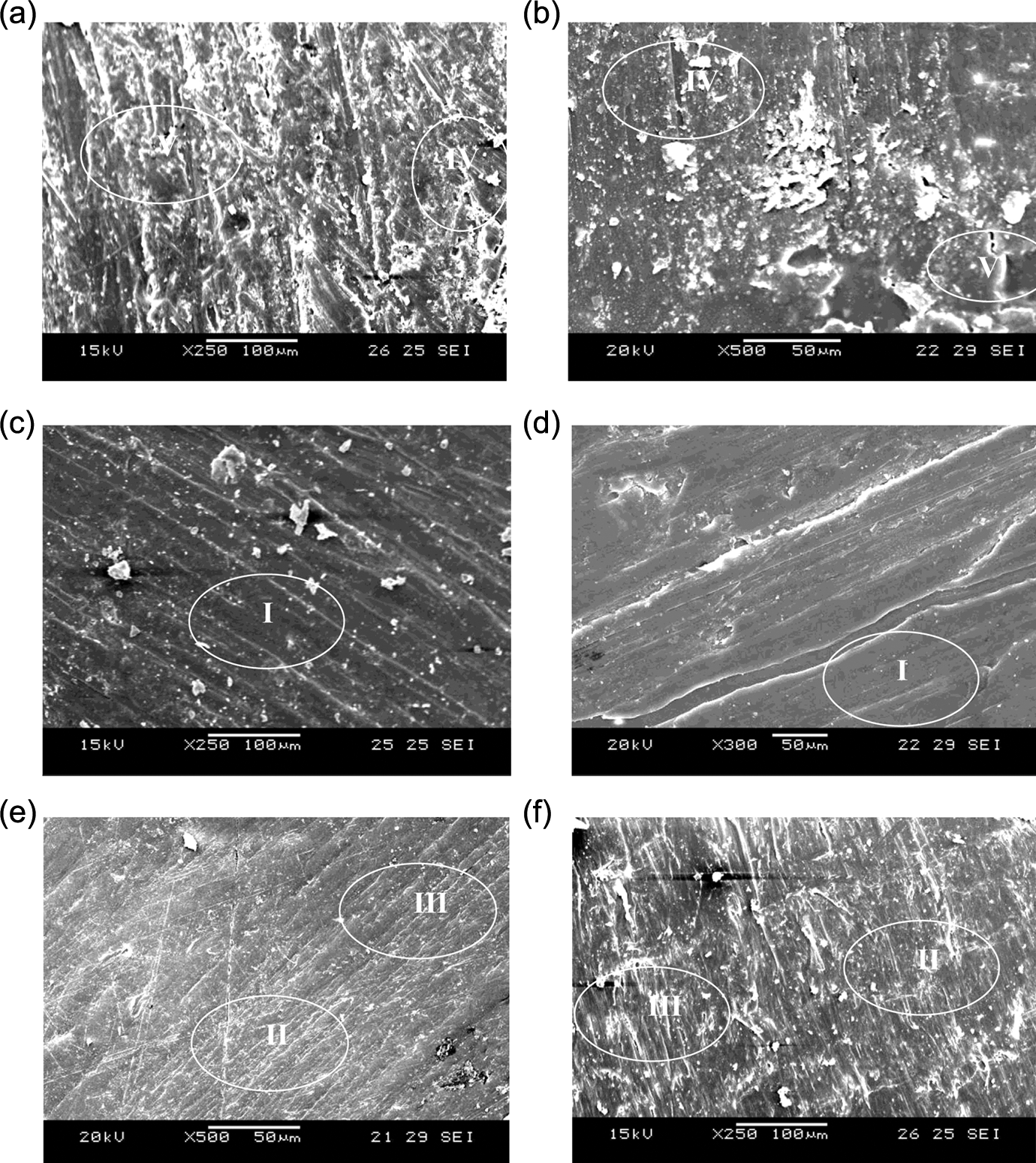
SEM images of worn out specimens. (a) UHMWPE at MT of 260°C, (b) γ-UHMWPE at MT of 260°C, (c) UHMWPE at MT of 280°C, (d) γ-UHMWPE at MT of 280°C, (e) UHMWPE at MT of 300°C and (f) γ-UHMWPE at MT of 300°C. I: ironing; II: scratching; III: ploughing; IV: plastic deformation; V: fatigue wear.
However, these frozen layers did not significantly influence the COF and wear rate due to repeated sliding process, and the heat accumulated in the contacting surface causes the thermal softening of UHMWPE. These softening surfaces transferred thin film that acts as a lubricant providing good lubrication. This could be one of the reasons that the wear rate decreased for certain injection molding conditions. That is, the lubrication effect reduces the adhesive interaction in the contacting asperities and reduces the shear stress. 21
The presence of wear mechanisms such as ploughing, plastic deformation, and fatigue in UHMWPE has proved that wear particles follow the plate-like patterns. On the other hand, the presence of wear mechanisms such as, ironing, marking, or scratching indicates the wear pattern is in the form of fine particles. 22 Therefore, the decreased wear rate for γ-UHMWPE is attributed to the elevated number of carbon covalent that might have increased the resistance to plastic deformation and fibrillar pull out. 23 The carbon free radicals formed during radiation (“primary free radicals”) in the amorphous region of the semicrystalline UHMWPE possess enough mobility to recombine to form cross links in the polymer. 24 Also it is understood from the studies of Fu et al. that the increase in toughness due to cross linking might also be one of the reasons for decreased wear rate. 25
The SEM micrographs indicate that samples corresponding to MT of 280°C were dominated by ironing. The samples corresponding to MT of 300°C were dominated by scratching and ploughing. The most destructive mechanisms such as plastic deformation and fatigue wear were predominant for the samples obtained at 260°C. The bonding strength between diffused structures of UHMWPE particles at MT of 260°C is comparatively weak, and ductile fracture occurs at defect point. This discontinuity of UHMWPE will result in poor mechanical properties and lower WR. The SEM micrographs of the worn out surface for UHMWPE specimens molded at MT of 280°C can be viewed as uniform smoother and lesser intergranular discontinuity found on the frozen layer. This diffused structure of UHMWPE powders at MT of 280°C is sufficient for the molecular chain to migrate across grain boundaries. It seems that the UHMWPE specimens prepared at MT of 280°C have a better mechanical property and higher WR. It is observed that the above-mentioned results of SEM micrograph are well correlating with the results of graphical representation. The above-mentioned wear mechanisms can be classified into two groups: one is abrasive wear and the other is adhesive wear. The ploughing and scratching falls under the category of abrasive, whereas the plastic deformation and fatigue wear come under the category of adhesive wear. 26
Conclusions
The wear behavior of γ-irradiated UHMWPE on comparison with unirradiated UHMWPE in a hip joint simulator was studied. The following conclusions are drawn from the results. The microhardness of UHMWPE corresponding to MT of 280°C was higher than those of 260°C and 300°C because proper bonding is achieved in MT of 280°C UHMWPE specimens. The COF and wear rate of UHMWPE and γ-UHMWPE are minimum for specimens corresponding to MT of 280°C, whereas the specimens obtained at MTs of 260°C and 300°C have more COF and wear rate. Ironing is the predominant mechanism for the specimens corresponding to MT of 280°C, whereas ploughing and scratching mechanisms are predominant for the specimens obtained at MT of 300°C. The specimens corresponding to MT of 260°C were dominated by plastic deformation and fatigue wear. γ-Irradiated UHMWPE specimen has high microhardness, frictional, and WR when compared to that of unirradiated UHMWPE. The cross-linked structure of polymer chains is mainly attributed to the enhanced friction and wear behavior of γ-irradiated UHMWPE. Finally, it can be concluded that the UHMWPE specimens cross linked by γ-irradiation with radiation dose of 25 kGy have improved the friction and wear behavior of UHMWPE.
Footnotes
Declaration of Conflicting Interests
The author(s) declared no potential conflicts of interest with respect to the research, authorship, and/or publication of this article.
Funding
The author(s) received no financial support for the research, authorship, and/or publication of this article.