
Abstract
In recent years, there has been increasing interest in the development of wood–plastic composites (WPC) for use as building materials. Using wood as natural reinforcement in composite materials, instead of mineral reinforcements, has several advantages such as low density, low cost, and less abrasive finish. The natural reinforcements are also non-toxic and recyclable. The wide variety of WPCs makes it difficult to discuss the performance of these composites. In this research, the bubble inflation technique, introduced by Joye et al., is used to study the behaviour of biocomposite materials in cold temperatures. The results of experiments with high-density polyethylene and WPC membranes with 20, 30, 40, 50 and 60 wt% of wood fibre, under the combined effect of temperature and pressure are presented. The membranes are tested under the maximum pressure of 18 psi within the temperature range of −50C to +50°C with 25°C increments.
Introduction
In recent years, due to abundance, low cost, and processability of wood as a filler, there has been increasing interest in the development of wood–plastic composites (WPC) for use as building materials. One reason that this fairly new material has outperformed competing plastic products in decking is that the addition of wood filler is an effective way to increase product stiffness, although strength usually suffers. 1
Using wood as natural reinforcement in composite materials, instead of mineral reinforcements, has several advantages such as low density, low cost and less abrasive finish. The natural reinforcements are also non-toxic and recyclable.
The term WPC refers to any composite that contains wood (of any form) and thermosets or thermoplastics. Thermosets are plastics that, once cured, cannot be melted by reheating. These include resins such as epoxies and phenolics. Thermoplastics are plastics that can be repeatedly melted, such as polyethylene (PE) and polyvinyl chloride. 1 This study focuses on WPCs, which are most often simply referred to as WPCs with the understanding that the plastic component is a thermoplastic.
Due to the limited thermal stability of wood, only thermoplastics that melt or can be processed at temperatures below 200°C are commonly used in WPCs. Currently, most WPCs are made with PE, both recycled and virgin, for use in exterior building components. However, WPCs made with wood–polypropylene are typically used in automotive applications and consumer products, and these composites have recently been investigated for use in building profiles. Polystyrene and acrylonitrile–butadiene–styrene are also being used. The plastic is often selected based on its inherent properties, availability and cost; the product need and the manufacturer’s familiarity with the material. 1
The wood used in WPCs is most often in particulate form such as wood flour or very short fibres, rather than longer individual wood fibres. Products typically contain approximately 50% wood, although some composites contain very little wood and others as much as 70%.
Wood and plastics are not the only components in the WPCs. These composites also contain materials that are added in small amount to affect processing and performance. Although formulations are highly proprietary, additives such as coupling agents, light stabilizers, pigments, lubricants, fungicides and foaming agents are all used to some extent. 1
The wide variety of WPCs makes it difficult to discuss the performance of these composites. Performance depends on the inherent properties of the constituent materials, interactions between these materials, processing, product design and service environment. Adding wood to unfilled plastic can significantly increase its stiffness but can often make it more brittle. Most commercial WPC products are considerably less stiff than solid woods. Adding fibres rather than flour increases mechanical properties such as strength, elongation, and unnotched Izod impact energy. 1 Since WPCs absorb less moisture, and do so more slowly than solid wood, they have better fungal resistance and dimensional stability when exposed to moisture.
The increased use of WPCs in the last decade has made it essential for researchers to perform computer-aided polymer analysis on them. The recent progress demonstrates the need for accurate description of the material behaviour under the combined effects of applied stress and temperature. 2
From the experimental point of view, there are several approaches to determine the mechanical properties of rubbers and thermoplastics. In general, for these tests the measured variables are the displacement, strain, force and time. Treolar 3 performed one-dimensional tests. The test consists of a simple extension, simple shear and uniaxial compression.
There are three different types of two-dimensional tests:
The equibiaxial extension on a rectangular membrane 4 : a test to stretch a thermoplastic membrane in two directions, the XY plane of the membrane, leaving the third direction free.
Blowing a biaxial axisymmetric membrane 3,5 –8 : a test to blow an initially flat circular membrane with the air flow.
Extension and simultaneous blowing of a hollow axisymmetric cylinder 9,10 : a test to use the stretch forces for extension, while at the same time blowing the cylinder using the air flow.
In this research, the bubble inflation technique, introduced by Joye et al., 5 is used to study the behaviour of WPCs in cold temperatures. The WPC samples used in this research are manufactured at the plastic laboratory at the University of Quebec at Abitibi-Temiscamingue (UQAT), Canada.
Materials and experimental setup
Material preparation
The manufacturing of thermoplastic composites is often a two-step process. Compounding and pelletizing is followed by either extrusion or injection moulding (IM). In the plastic laboratory at UQAT, a Cincinnati Milacron extruder (55 mm counterrotating conical twin-screw extruder having length/diameter ratio of 22:1) is used to compound the dry chemithermomechanical pulp (CTMP) fibres at a proportion of 40 wt% and high-density PE (HDPE) at 60 wt%. The obtained compound is then air cooled and grinded with a Nelmor (USA) rotary knife grinder equipped with a screen with a 9.6 mm diameter opening to form WPC pellets. In the second stage of the process, composites are formed using either extrusion or IM. A Cincinnati Milacron 35-mm conical counterrotating twin-screw extruder is used to form extruded samples. The length-to-front diameter ratio of the screws is 23:1. A Sumitomo (Japan) 55-US ton SE-DU Series injection moulding machine is used to form injection-moulded samples.
The composites are prepared in a Haake Rheomix (USA) 600p twin-screw mixer (Roller-Rotors R600) at 170°C and 60 r/min. Stamylan 8621 and fusabond were initially introduced and mixed for 90 s to ensure complete melting of the polymer. Then, the wood flour was introduced and mixed for 4 min. The WPC samples with 20, 30, 40, 50, and 60 wt% of wood are cut into circular shapes with 79.2 mm of diameter to form a membrane for bubble inflation tests.
Experimental setup
The experimental set-up is to model the free flow of thin circular membranes under the effect of pressure. In this context, it is necessary to establish an experimental set-up that is robust and provides accurate data for mechanical modelling. During each test the following measurements are carried out:
the vertical displacement of the pole of the membrane, which is mostly referred to as bubble height;
the air pressure during the experiment;
the airflow for each experiment;
the temperature inside the environmental test chamber and
the duration of the test.
All these measurements are carried out for a period of a few seconds during the blowing process. It must be emphasized that the quality of the experimental data plays a vital role in the future work concerning the problem of identification of mechanical parameters. Indeed, the experimental set-up must meet several technical criteria such as, accuracy, data transfer speed, repeatability, and adaptability to the existing safety and handling standards.
For each type of material, membranes with the diameter of 79.2 mm are prepared. The blowing of these membranes is carried out by means of airflow. To preserve the repeatability of the experiments, a set of three tests is performed for each material and each condition. The average error for pressure measurement is in the order of 5%. The temperature considered for the tests varies from −50 to +50°C.The experimental set-up consists of four distinctive parts:
the cylinder with the membrane on top that is connected to the pressured air line and measuring instruments;
the environmental test chamber with a temperature range of −70 to +180°C;
the measuring unit, consisting of a pressure regulator, two pressure transducers, one flow meter, a thermocouple and a laser distance sensor. This unit sends analogue signals to the data acquisition system and
the data acquisition system connected to the measuring instruments and a computer. The data acquisition system converts the analogue signals from the measuring unit to digital data readable by a computer.
The cylinder works as a buffer tank that inflates the membrane with pressured air. A metal tube is welded to the bottom centre of the cylinder that is connected to the pressured air line. The pressured air in the cylinder is distributed uniformly on the bottom surface of the membrane. The uniform distribution of air is provided by a metal diffuser that is placed in the middle of the cylinder on top of the metal tube as a cap. The diffuser has a hemispheric shape with holes on its surface to diffuse the airflow.
It is very important to make sure that the system is properly sealed and there is absolutely no air leaking out of the system. For this purpose, we performed two different tests to check the air leakage. In the first test, a membrane was mounted on the system and the cylinder was filled with pressured air. The pressure was set to 80 psi, and the cylinder was placed in a tank filled with water. Bubbles released in the water would reveal any small leakage in the system. In the second test, the system is kept under constant pressure for several minutes. Any small leakage in the system would be detected by changes of pressure with time. Ideally, the pressure must remain constant for a long period of time.
The cylinder is placed inside the environmental test chamber, and it is screwed on to the bottom surface of the chamber to remove any potential vibrations. A hanger is attached to the side wall of the chamber for the laser distance sensor to measure the bubble height of the membrane during the experiment.
During each test, the door of the chamber is shut and sealed to keep a uniform temperature distribution inside the chamber. There is a 1-in. diameter opening on the side wall of the chamber that is used for passing the pressured air line, thermocouple and the cable for the laser distance sensor.
For each test, 40 min is allowed for heating and cooling process until the chamber reaches the target temperature. The membrane is kept at the target temperature for the duration of 8 h to make sure that it has reached a uniform temperature distribution condition through the whole material before the test.
To measure and record the temperature inside the chamber, two references are used. The first one is the control unit of the environmental test chamber that reports the temperature inside the chamber throughout the whole test. The desired temperature and humidity can be set by using the same control unit on the chamber.
The second reference temperature is the thermocouple that is placed close to the membrane and records the temperature using the data acquisition system. The thermocouple sends the analogue signals to the data acquisition system connected to the computer. The computer reads the signals and converts them to the equivalent values of temperature. The temperature values are recorded in a datasheet along with the data for the air pressure, airflow, bubble height and the test duration.
A single closed-loop pressure regulator that converts a variable electrical signal into a variable pneumatic output is used to control the air pressure of the system. The flow metre is right after the pressure regulator in the measuring unit and records the values of airflow for each experiment. The air enters the measuring unit through the pressure regulator and passes one flow metre and two pressure sensors to enter the cylinder. At the same time, the thermocouple and the laser distance sensor report the values of temperature and deformation.
A position sensor, which performs the distance measurement without a contact with the target, is used to monitor the height of the bubble at the centre of the membrane. The measurement range is between 5.00 and 35.00 cm. A laser beam, emitted by the sensor before the blowing adjusts the central position of the membrane. The position sensor receives the reflection of the laser beam and measures the distance during the blowing. The electrical signal of the measurement is sent to the data acquisition system and the computer to be recorded in the datasheet.
The tests are to plot the pressure changes against the bubble height at the pole of the membrane. The testing system is set-up in the CIGELE laboratory at the University of Quebec at Chicoutimi, Canada. To understand the effect of wood fibres in the mechanical properties of the material, the results are compared with the results of bubble inflation experiments using raw HDPE as the membrane.
Results and discussion
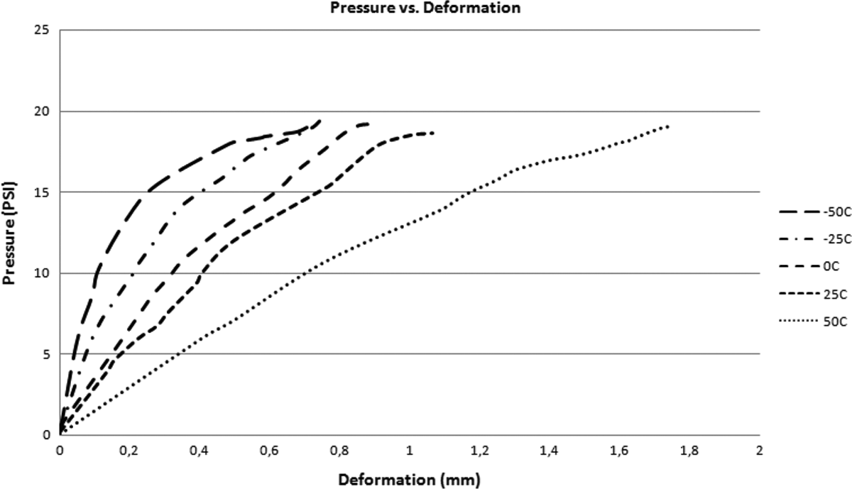
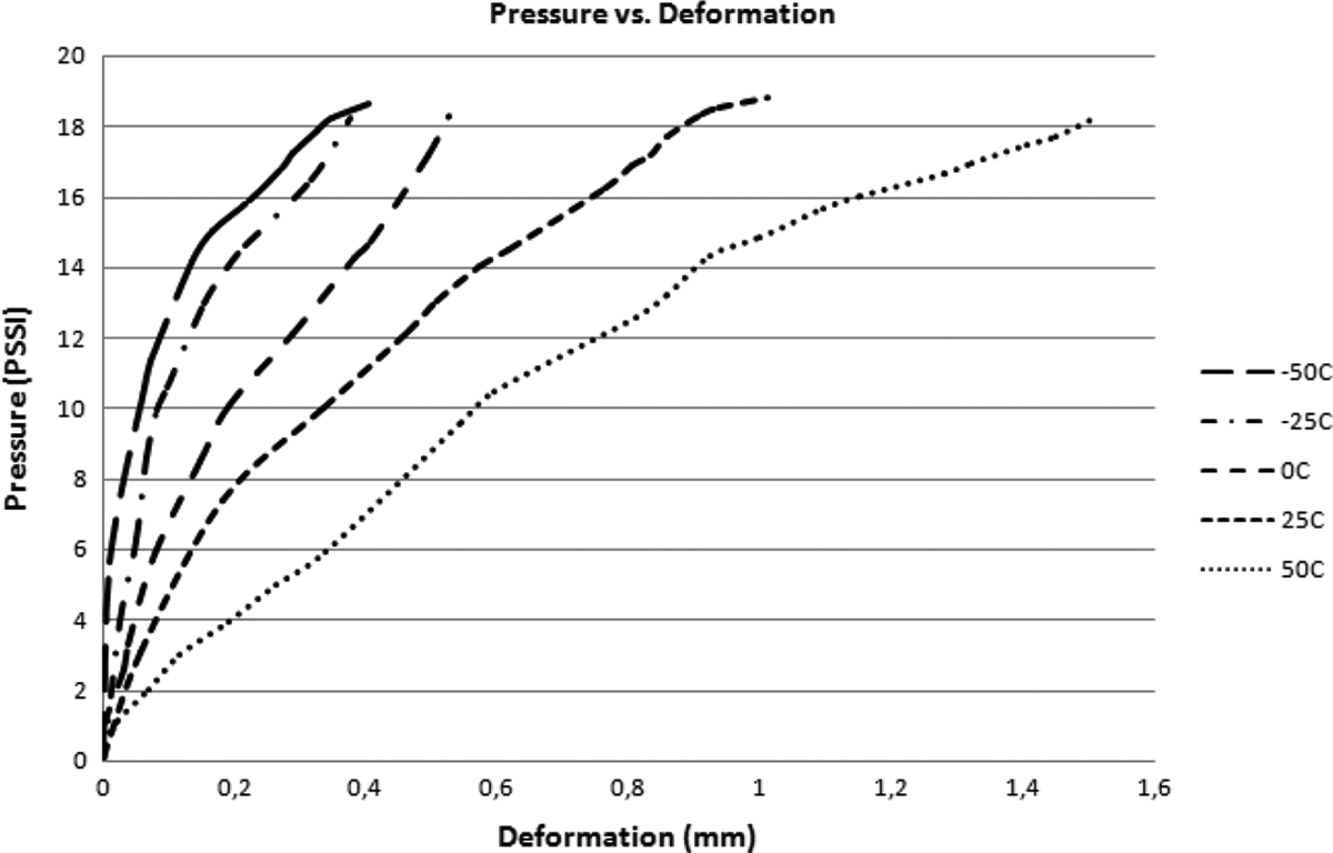
This section presents the results of experiments with HDPE and WPC membranes with 20, 30, 40, 50, and 60 wt% of wood fibre, under the combined effect of temperature and pressure. The membranes are tested within the temperature range of −50° to +50° with 25°C increments. The membranes are tested under the maximum pressure of 18 psi. Each membrane was kept in the environmental test chamber for the duration of 8 h, in order to reach a uniform temperature distribution throughout the whole membrane. Each experiment is repeated three times, and the results are presented for each membrane in each temperature, which represent the average of three experiments.
Figure 1 shows the deformation of HDPE at different temperatures under the maximum pressure of 18 psi.
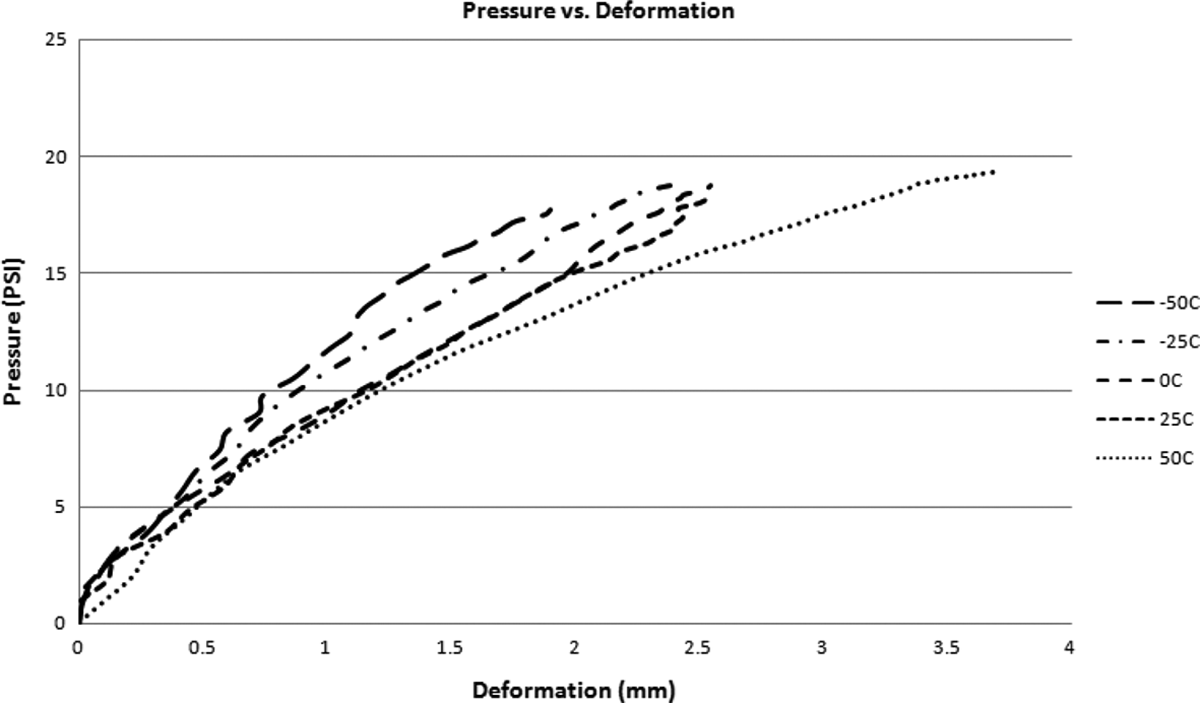
Deformation versus pressure for HDPE. HDPE: high-density polyethylene.
Figures 2 to 6 show the deformation of WPCs with 20, 30, 40, 50 and 60 wt% of wood fibre using the bubble inflation technique at different temperatures under the maximum pressure of 18 psi.
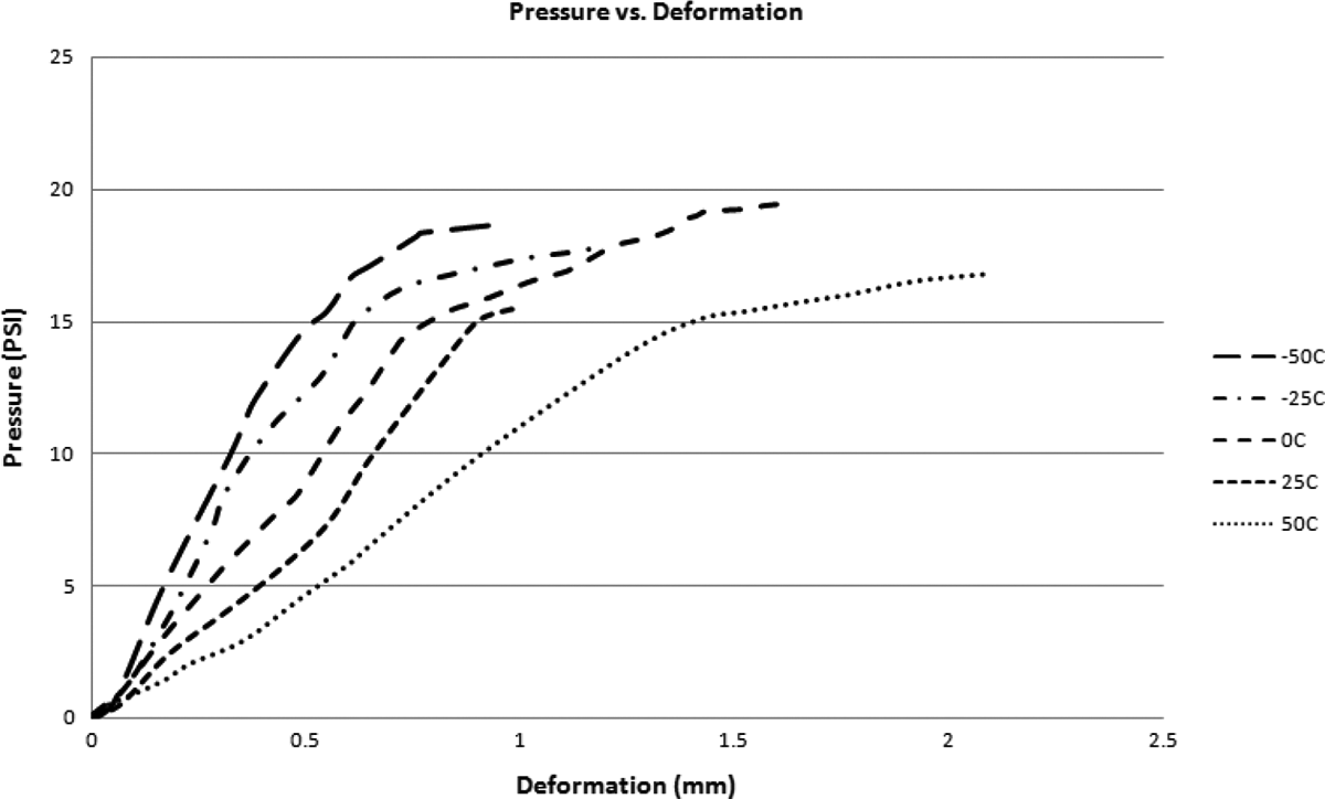
Pressure versus deformation for WPC20%. WPC: wood–plastic composite.
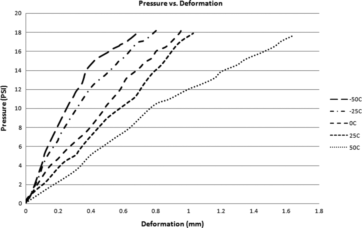
Pressure versus deformation for WPC30%. WPC: wood–plastic composite.
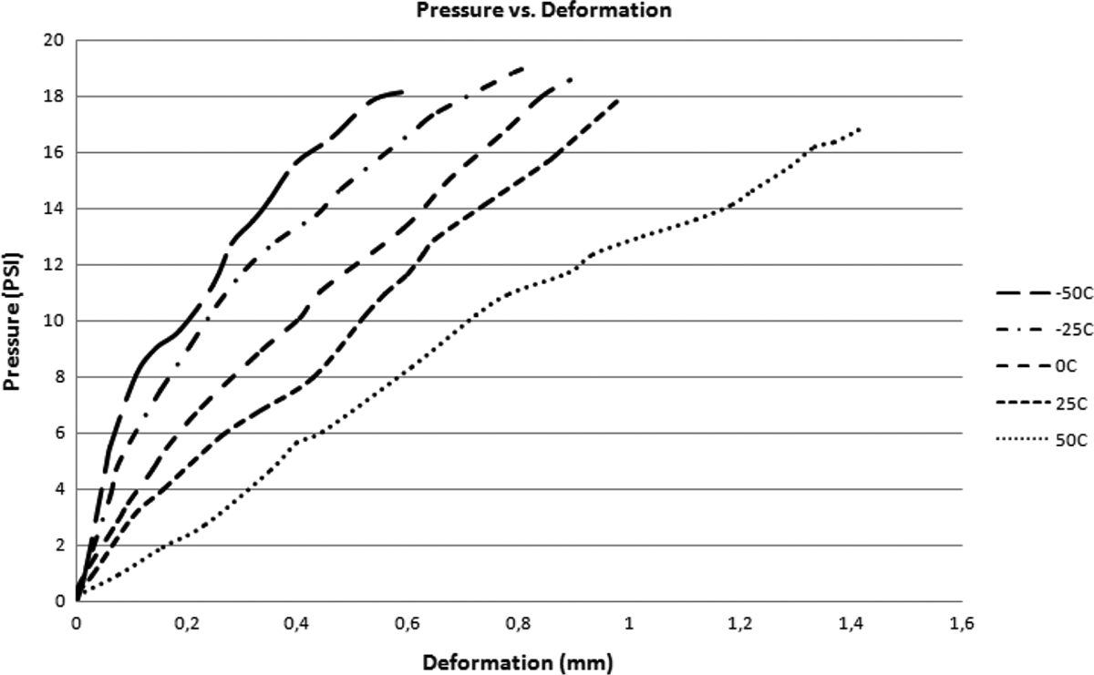
Pressure versus deformation for WPC40%. WPC: wood–plastic composite.
Pressure versus deformation for WPC50%. WPC: wood–plastic composite.
Pressure versus deformation for WPC60%. WPC: wood–plastic composite.
It is observed that WPCs and HDPE are elastic in response to pressure at cold temperatures. Erchiqui et al. 11 studied the viscoelasticity of these materials at thermoforming temperatures. During the inflation, the maximum height is in the centre of the membrane.
It is observed that the deformation of the membrane, under the same pressure, decreases with decreasing temperature. Therefore, it can be understood that the material has a higher stiffness in cold temperatures even though it may become more brittle.
For HDPE, the maximum deformation at 50°C is measured as 3.7 mm. However, the maximum deformation at −50°C is only 1.9 mm. For WPC with 60 wt% of wood fibre, the maximum deformation at 50°C is measured as 1.52 mm, and the maximum deformation at −50°C is 0.40 mm. Figures 7 and 8 compare the deformation of different membranes at +50 and −50°C.
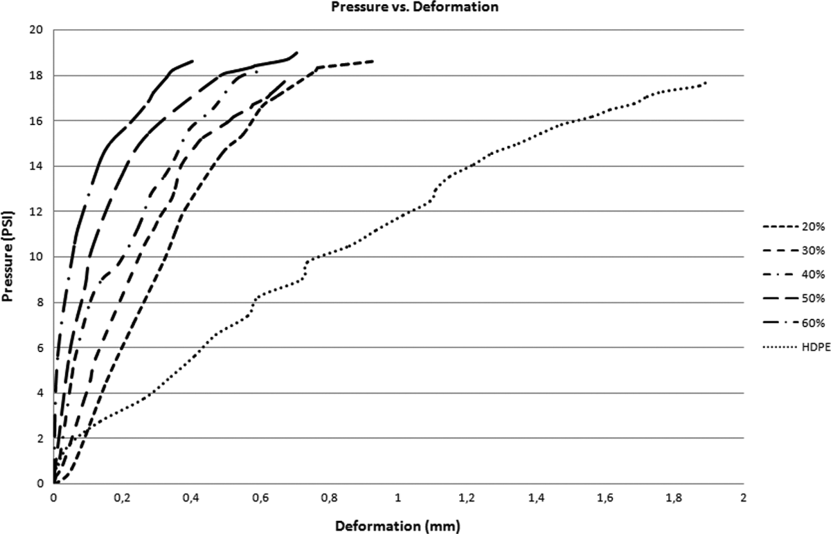
Deformation of different membranes at −50°C.
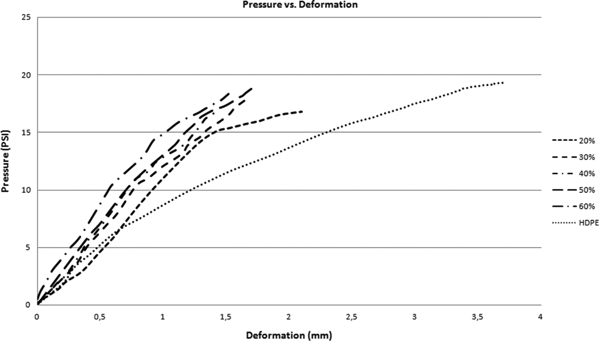
Deformation of different membranes at +50°C.
It is observed that the addition of wood fibre increases the material performance under the pressure at different temperatures. However, as is can be seen from Figures 7 and 8, at colder temperatures the difference between the deformations of WPCs and HDPE is much higher as compared to high temperatures.
Conclusion
In recent years, there has been increasing interest in the development of WPCs for use as building materials. Using wood as natural reinforcement in composite materials, instead of mineral reinforcements, has several advantages such as low density, low cost and less abrasive finish. The natural reinforcements are also non-toxic and recyclable.
The wide variety of WPCs makes it difficult to discuss the performance of these composites. In this research, the bubble inflation technique, introduced by Joye et al., 5 is used to investigate the elastic deformation of WPCs and HDPE in cold temperatures. To the best of our knowledge, the elastic deformation of these materials at cold temperatures has not been investigated thus far. The WPC samples used for characterization are manufactured at the plastic laboratory at University of Quebec at Abitibi-Temiscamingue, Canada.
The results of experiments with HDPE and WPC membranes with 20, 30, 40, 50 and 60 wt% of wood fibre, under the combined effect of temperature and pressure are presented. The membranes were tested within the temperature range of −50 to +50°C with 25°C increments and under the maximum pressure of 18 psi.
It was observed that HDPE and WPCs are elastic in response to pressure at cold temperatures. The addition of wood fibre in raw HDPE leads to less deformation under the pressure and this contribution is more significant as temperature decreases.
Footnotes
Funding
This research received no specific grant from any funding agency in the public, commercial or not-for-profit sectors.