
Abstract
Thermoplastic tape placement opens the possibility of a fully automated composite production. The resulting quality is highly dependent on the thermal history during consolidation. This article focuses on the thermal modelling of a tape placement system employing a near-infrared laser. A nonlinear two-dimensional finite element model is presented for a carbon fibre reinforced thermoplastic (AS4/PEEK) composite placement process using a conformable roller. The relative influence of roller geometry, roller temperature and thermal contact resistance was studied. Temperature measurements were performed using thermocouples welded to the substrate. The model predictions show good correlation in terms of timing of the irradiation, shadow and consolidation regions. The roller temperature was found to have the most significant impact on the bond line temperature distribution.
Introduction
The high specific strength and stiffness of fibre-reinforced polymer composites make them an attractive choice of material for use in lightweight and high-performance structures. The manufacturing process for composite materials is normally associated with being slow due to the labour-intensive lay-up processes followed by long cure cycles due to the use of thermoset resins. In the case of high-performance composites, the additional costs associated with preimpregnated materials and autoclave cure must also be considered. Technologies such as filament winding and automated tape placement (ATP) have the ability to eliminate the labour-intensive lay-up process, however the long cure cycles still remain.
The use of thermoplastic composites eliminates long cure cycles as they can be processed in situ. Thermoplastic materials are processed by fusion bonding: heat and pressure are applied to the interface being joined and the polymer molecules diffuse across the interface forming a bond. As no solvents are involved, negligible emissions are produced, making it a very clean process. Furthermore, when coupled with a placement technology such as ATP, the composite can be bonded in situ as it is placed. This means that once the placement is done, the component is ready for use and the cure cycle is eliminated, making the process time much shorter.
The in situ thermoplastic ATP process is an attractive manufacturing technique as it is faster, cleaner and automated. While research has been conducted in the area, the process has not yet reached maturity. A complete understanding of the process and ability to accurately predict material quality in real processes is required in order for industry to adopt the technology.
Thermoplastic tape placement
The in situ thermoplastic ATP process is described in Figure 1. Unidirectional preimpregnated tape is fed down to the top surface of the previously placed layers (substrate). A heat source, such as a laser, heats the surfaces of the tape and substrate as they approach the nip point. The melted surfaces of the tape and the substrate are pushed together by the consolidation device, resulting in a bond. Layers are formed by placing multiple tapes side by side. Parts are made by building up laminates layer by layer.
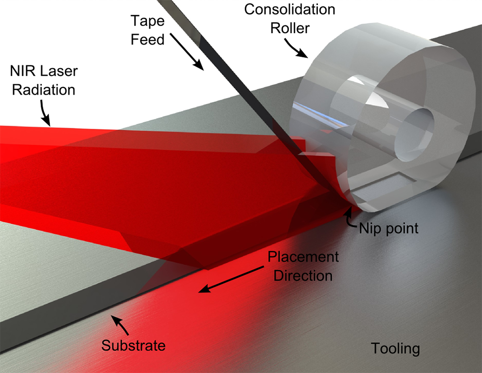
Laser-assisted tape placement process showing typical laser beam propagation and conformable roller.
Interlaminar strength development
The strength development process for thermoplastic bonding has been widely studied as overviewed in. 1 The fundamental mechanism of strength development is the inter-diffusion of polymer chains across the bond interface, a process known as autohesion. 2 –4 Polymer chains migrate across the interface over time due to diffusion, increasing the distance in which they have penetrated the boundary. When a certain level of penetration is achieved, the apparent strength of the interface will equal that of the bulk material. As it is a diffusion process, the rate of autohesion is highly temperature dependent.
As real surfaces are not perfectly flat, the initial contact is limited to asperities on the surface. 5,6 As temperature and pressure are applied, the material softens and begins to flow, increasing the level of contact. Complete intimate contact can be achieved, given sufficient time, temperature and pressure application.
The bond strength development process is therefore modelled by combining autohesion and intimate contact development models. Thermoplastic bonding models therefore require an accurate account of the coupled temperature and pressure histories from the nip point onwards.
Factors affecting overall quality
Interlaminar strength development is the fundamental process for thermoplastic tape placement; however, it is only one of the many processes affecting the overall quality. Residual stresses are generated due to the mismatch in thermal properties between the fibre and the matrix and the non-uniform cooling rates through the thickness of the material. 7,8 Void expansion can occur when the material is heated without sufficient pressure application, 9 –12 therefore it is important to maintain consolidation pressure until the material solidifies. Thermal degradation will occur if the matrix is overheated. Cross-linking 13 and thermal decomposition 3,14 have been considered and are time and temperature dependent. In the case of semi-crystalline matrices, the resulting degree of crystallinity is dependent on the cooling rate. 14 –16 It can be seen that many of the factors affecting the final quality are highly dependent on the complete thermal history experienced during placement.
Laser-assisted tape placement
Carbon dioxide lasers with output powers of 65–80 W have been studied as a heat source for the closely related thermoplastic filament winding process. 17 –22 The typical output of such a laser is a small round spot at a wavelength of 10.6 μm. For composite processing, a line or rectangular distribution is preferred so as to produce uniform heating across the width of the tape and substrate. The round spot output of the source has been converted into line sources through the use of ZeSe lenses 17,19 –23 or galvanometer scanning. 18 The resulting lines are no more than 2 mm in width, making the process extremely sensitive to the laser position 22 and the bond quality is adversely affected by short dwell times. 20,21
Filament winding differs from tape placement in that the laser source remains stationary and the laser can be aimed directly into the nip point as the mandrel is curved. In tape placement, the beam must be aimed from an angle above the plane placement and therefore cannot be aimed directly into the nip point. A shadow is cast by the consolidation roller as a consequence of this limitation. Furthermore, high-power carbon dioxide laser sources are too bulky for direct mounting on a placement head, and the long wavelength of the radiation is not suited to fibre optic delivery. 22
The majority of the literature for thermoplastic tape placement is based on systems employing hot gas torches as the heat source. Heat delivery is limited due to the convective mode of heat transfer, and the operation costs are high as inert gases such as nitrogen must be used to prevent the oxidation of the composite. 23 Numerical models for laser tape placement have been studied 14,24,25 ; however, small heated lengths representing a line source are assumed and experimental validations are not performed.
In more recent times, near infra-red (NIR) diode lasers have been used as they are able to deliver higher heat fluxes, are more efficient and have a near instantaneous response that is ideal for process control. 26 Furthermore, the radiation can be delivered to compact, lightweight optics on a placement head via light cable owing to the lower wavelength (800–1000 nm) of the radiation. The laser tape placement system considered in this study utilises optics to produce an enlarged rectangular spot of uniform intensity, the size of which is position dependent due to beam divergence. The spot size used for a 12 mm tape is 45 mm long and 16 mm wide at a focal length of 127 mm, much larger than the spot sizes reported for carbon dioxide lasers. This allows for progressive and homogenous heating across the length and width of the tape as well as longer dwell times that enable higher placement rates. Thermal models for this type of laser tape placement process have not been reported in literature.
The thermal models in the tape placement literature assume rigid metallic rollers. The rollers have been approximated as a convective boundary condition with vastly differing heat transfer coefficients of 400, 14 500, 21,24,27 1000, 28,29 and 1500 W/m2.K9 or simply a fixed boundary temperature. 10 To the authors’ knowledge, there have been no studies that model the roller as a physical body and analyse its relative influence. Conformable rollers allow for placement on curved surfaces and irregular geometry. They can provide much longer and more uniform pressure distributions (Figure 1). The result is an increase in the amount of time available for consolidation for a given process speed as well as a much larger area of thermal contact with the roller. Since the process is highly dependent on the post nip point temperature history, it is therefore of interest to model the effect of this contact on the thermal history.
This article will (1) present a thermal model of the NIR laser-assisted tape placement process utilising a conformable elastomeric roller, (2) present an initial experimental validation and (3) investigate the effects of the roller geometry, roller temperature and roller-to-composite contact resistance on the post nip point temperature distributions. In contrast to earlier studies where the roller is modelled as a boundary condition, the roller will be physically modelled.
Thermal model
The layout of the placement system in question is shown in Figure 1. A rectangular laser spot is aimed at the nip point. The spot overshoots the width of the tape by 2 mm per side to ensure uniform temperature across the width of the consolidation zone. The size of the laser spot is dependent on the position due to beam divergence. The tape is fed at an angle of approximately 50°. Consolidation pressure is applied with a conformable roller that deforms significantly. In this study, a single tape is placed at rate of 8 m/min onto a 25 ply unidirectional laminate. As the rectangular spot of the laser heats the tape evenly across the width, and the transverse thermal diffusivity is low, a two-dimensional (2D) model is therefore sufficient to model the system for the purpose of this study.
Methodology
Various 1D simplifications 9,10 have been made in the literature as the heat flow in the process direction is small compared to the mass flows. The most common approach is a 2D model with an Eulerian frame of reference attached to the placement head, and this approach has been justified when the tape and substrate are heated uniformly across the width. 14,21,24,25,27,30 Kim et al. 28 suggest a 3D model for non-uniform hot gas impingement. In this study the tape and substrate are heated uniformly across the width, therefore a nonlinear steady state 2D finite element approach was implemented in ANSYS 13.0. The reference frame for the analysis was fixed to the placement head. Due to the translation of the head during placement, the tooling, tape and substrate pass through the reference frame as indicated by the arrows in Figure 2. The roller is also rotating within the reference frame, carrying heat away from the nip point. These mass flows are significant and therefore must be taken into consideration.
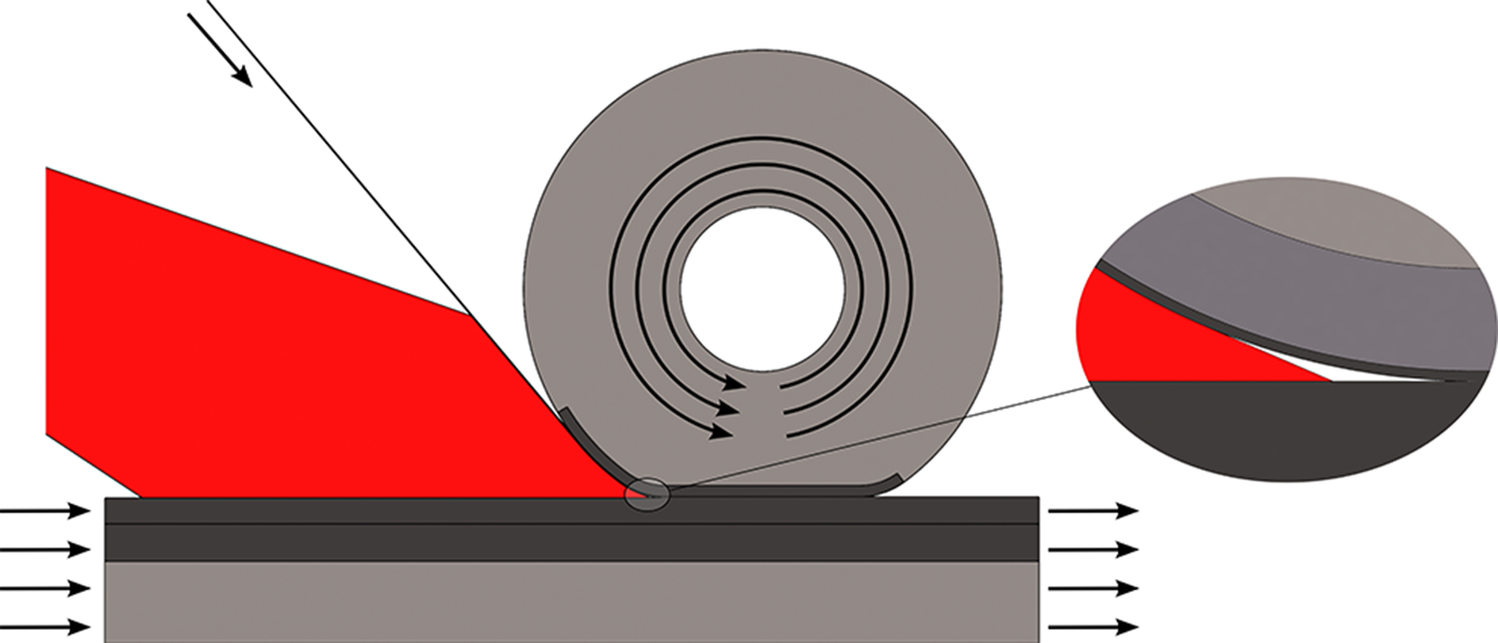
Reduced geometry (dark grey) overlayed on the original geometry (light grey). The positioning of the laser causes a small shaded region prior to the nip point. Arrows indicate the mass flows.
ANSYS thermal element type PLANE55 is the first-order quadrilateral element capable of mass transport heat flow for constant velocity fields. This is taken into account by adding a velocity vector to the thermal energy balance equation so as to include the mass transport of heat. In the case of a 2D analysis, the partial differential equation is of the form:

where:
The size of the elements must be sufficiently small to prevent oscillations in the solution. The solution is valid for Peclet numbers less than unity.
31
The Peclet number is defined as follows:

Thus, the maximum element dimension (l) aligned with the flow vector is dependent on the thermal diffusivity (α) of the material and the magnitude of velocity (v). The maximum element dimensions for the materials used in the current model were calculated and are shown in Table 1.
Maximum element dimensions in direction of flow for an 8 m/min placement rate.
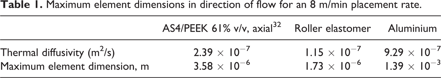
It can be seen that the mesh must be extremely fine in the direction of the mass flow for the roller. To minimise computational effort, the elements for the roller are meshed with high aspect ratios in the areas away from the contact boundary. The size requirement for the composite is also relatively small.
Model geometry
Due to the small element sizes required, particularly in the case of the roller, a large number of elements are required to achieve a valid solution. Due to the very low thermal diffusivity of the roller elastomer and the relatively fast mass transport, it was found that the temperature distribution has a small penetration into the roller. Iterative geometry reductions found that the roller geometry could be modelled as a slender strip of material along the boundary of the tape (Figure 2). The tooling could also be reduced in a similar fashion.
The dimensions of the reduced geometry are shown in Figure 3. The geometry of the irradiated region was estimated from process monitoring videos recorded by a camera mounted on the placement head. Note the shape of the conformed roller is modelled as a chord of the undeformed roller shape with radiused corners.
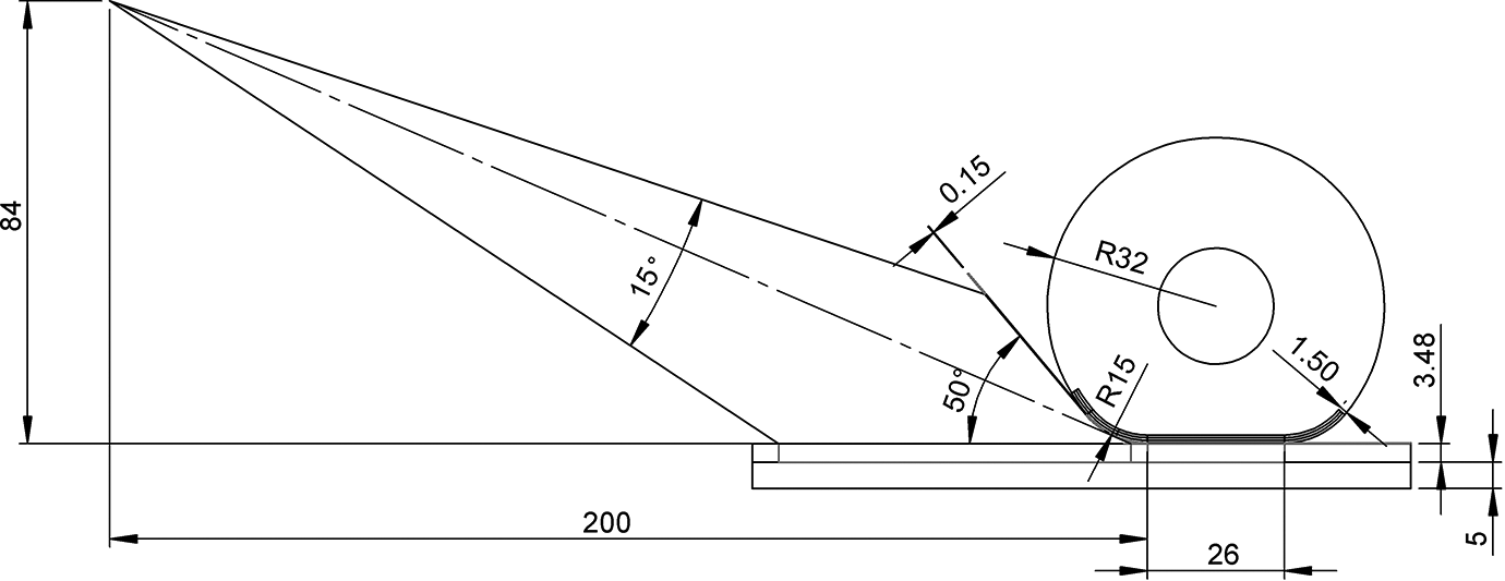
Dimensions of the reduced model geometry.
Detail of the refined mesh is shown in Figure 4. A large number of elements was required to meet the required Peclet number as well as a converged result for the through – thickness temperature distribution. The roller, composite and tooling contain 1.3, 0.4 and 0.2 million elements, respectively.
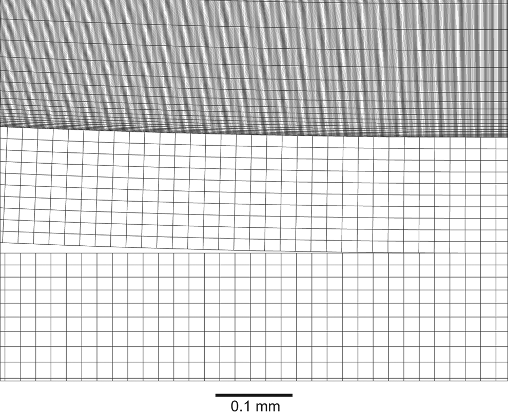
Detail of the roller, tape and substrate mesh at the nip point.
Mass transport
Mass flow was assumed to be uniform and laminar; therefore, the placement velocity was assigned to the elements in regions of linear flow such as the tooling, substrate and tape feed. In the regions where the material moves in a curved path (such as the roller and the tape prior to the nip point), local cylindrical coordinate systems were defined for each respective region of curvature. Velocity is assigned to each element based on the radial distance from the local origin, so as to maintain a constant angular velocity.
Laser heat flux
The typical mounting location for the laser creates a shaded region just prior to the nip point (Figure 2). The literature for in situ laser processing of composites assumes uniform heat flux distributions in the nip point region to approximate the laser heat input, excluding any effects of shadowing. An exception is the study by Grove 24 in which 2D ray tracing calculations were used to predict the heat flux distribution. For this model, radiation was simplified as a uniform heat flux over the illuminated regions, therefore taking the shaded regions into consideration. The degree of overshoot of the laser spot across the width of the tape and the absorptivity of the material was not known; therefore, it was not possible to accurately calculate the incident heat flux. Agarwal et al. 21 found large discrepancies between the experimental and modelled laser power requirement, which was attributed to reflections. The focus of this study is to investigate the effect of the consolidation roller on the post nip point history, and therefore accurate determination of the laser heat flux is considered to be unnecessary for the purpose of this model. The heat flux was adjusted so as to match the nip point temperature recorded in the experimental work.
Convection
Convection loads were applied to all surfaces exposed to the ambient environment. Laminar natural convection on a horizontal plate was assumed for calculation. Equation (2) is suitable for such conditions.
33

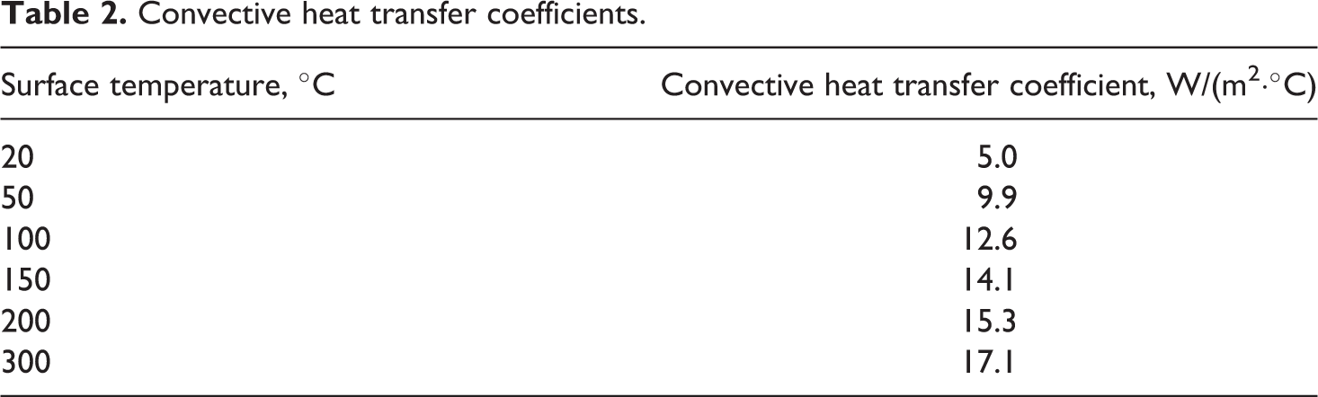
Convection coefficients were subsequently calculated for a characteristic length L = 0.01 m under ambient conditions. The coefficients are listed in Table 2.
Convective heat transfer coefficients.
Contacts and mass flow boundary conditions
Pure thermal contact is initially assumed for all contact boundaries between the roller, tape, substrate and tooling. The substrate is assumed to be a perfect 25 ply unidirectional laminate with no interlaminar thermal contact resistances. Ambient temperature is assigned to the incoming tape, substrate and tooling mass flow inlet boundaries. The inlet boundary for the reduced roller geometry is initially fixed at an estimated value of 100°C to replicate heat soak of the roller. Outlet boundaries are assumed to be perfectly insulated as the mass immediately outside the boundary will be at near to equal temperature. It should be noted that despite being perfectly insulated, heat still effectively travels through the boundary due to the velocity vector for the mass transport of heat. The heat effects due to crystallisation kinetics were not included as they are insignificant compared with the laser heat flux required for the studied placement rate.
Material properties
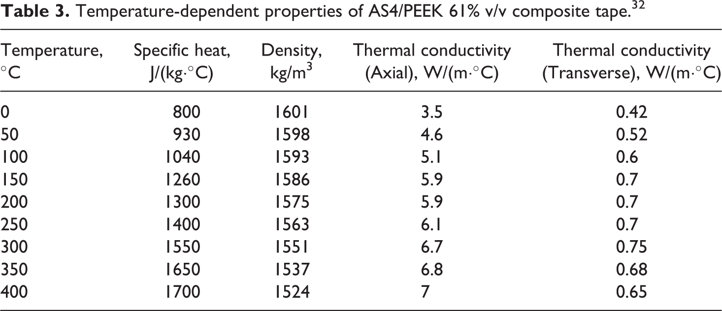
SupremTM T 60% v/v AS4/PEEK-150 0.15 × 12 mm unidirectional prepreg tape was used in the experimental work. It comprises of a polyetheretherketone (PEEK) matrix refinforced with AS4 carbon fibres. The specific thermal properties of this particular system were not available. The properties for an AS4/PEEK 61% v/v unidirectional tape were assumed as found in Table 3. Levy et al. 34 demonstrated that the degree of intimate contact can introduce a thermal contact resistance between the plies of a laminate. The experiments were performed at low pressures (1.34 kPa) with Cytec APC-2 prepreg, which has both high surface roughness and a significant intralaminar void fraction. The Suprem prepreg used in this work typically has a much smoother surface 26 and the average consolidation pressure under the roller was measured to be 180 kPa. For the purposes of this study, it is therefore assumed that perfect contact exists.
Temperature-dependent properties of AS4/PEEK 61% v/v composite tape. 32
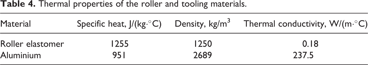
The thermal properties of the conformable roller and the aluminium tooling were assumed to be constant as temperature-dependent properties were not readily available. The properties assumed in this work are listed in Table 4.
Thermal properties of the roller and tooling materials.
Sensitivity analysis
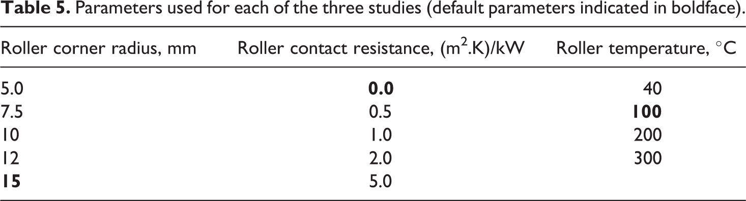
The effects of the roller temperature, contact resistance and corner radius were studied individually with respect to the default parameters (indicated in boldface in Table 5). The roller temperature was adjusted at the mass flow inlet boundary. Contact resistances were applied at the boundary between the roller and the composite. Various corner radii were applied while maintaining the same laser position relative to the nip point. Slight changes in the total irradiated length occur due to the change in size of the shaded region. The heat flux was adjusted accordingly so that the total heat input remained constant between the studies. The studied values are listed in Table 5.
Parameters used for each of the three studies (default parameters indicated in boldface).
Experimental
Experiments were performed at Advanced Fibre Placement Technology (AFPT) GmbH. The placement head is mounted on a six-axis robot. A control system regulates the laser power to maintain a constant temperature. In this study, the temperature along the bond line is of interest. This was measured by affixing thermocouples to the substrate. Due to the rapid placement rates and high heat inputs, temperature gradients can exceed 1000°C/s in laser tape placement. A 25 µm fine wire and a 12.7 µm foil K-type thermocouple were selected as they have a very fast response time. Measurements were logged at 100 Hz using a National Instruments cDAQ-9213 thermocouple module.
Initially a single ply of 12 mm AS4/PEEK tape was affixed to the surface of the tooling, spanning the length of the 700 × 300 × 16 mm aluminium plate. Twenty-four plies were then placed at 8 m/min with a process control temperature of 383°C. The result is a 25 ply unidirectional laminate. The thickness of the laminate was measured to be 3.48 mm and subsequently applied to the model geometry.
The thermocouples were then welded to the centre of the substrate surface of the composite using a soldering iron so as to maximise thermal contact without the use of adhesives that may influence the measurement. The temperature was logged while a single tape was placed on the substrate with the same process parameters. While the foil type thermocouple has a faster response time, it also has a relatively large surface area in comparison with the fine wire thermocouple and is therefore expected to reflect the laser to some degree, decreasing the accuracy of the measurement.
Results and discussion
The temperature plot for the default model parameters is shown in Figure 5. The model predicts localised surface heating of the composite with shallow penetration of the heat into the substrate and roller at the time of placement. This is due to a combination of the relatively fast motion of the placement head and the low transverse thermal diffusivity of the composite and roller. The incoming tape is heated quite uniformly through the thickness, prior to contact with the roller as the convective heat losses on both sides of the tape are insignificant compared with the heat input from the laser. When the tape contacts the roller, dissipation of heat occurs although the heat sink effect is small due to the low thermal diffusivity of the roller. Significant cooling of the tape surface is also predicted with the tape reaching a maximum of 380°C on the surface during heating yet dropping to 310°C immediately prior to the nip point. This is due to the dissipation of the heat away from the surface in the shaded region. A similar effect is observed on the substrate, however the shaded region is approximately half the size, thus the effect is not as large. This result suggests that significant overheating is required in order to achieve the nip point temperatures necessary for bonding, given the presence of a shaded region.
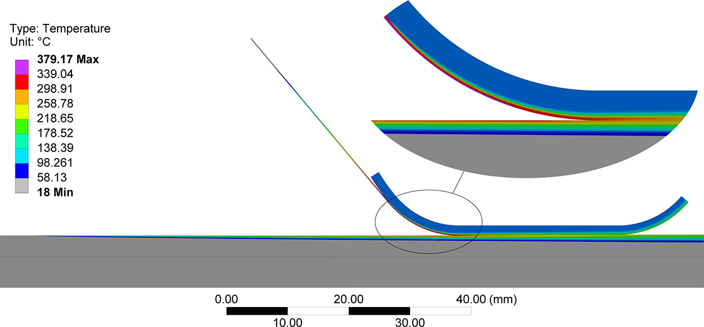
Temperature distribution for the default model parameters.
The measured substrate temperature is plotted in Figure 6 along with the model prediction. There is good agreement between the measured data and the prediction in terms of the timing of the events as shown by the notation in Figure 6, indicating the validity of the modelled geometry. The step at the start of the consolidation region is due the temperature differential between the tape and substrate. The prediction shows a hotter substrate coming into contact with a colder tape, whereas the measured data show the opposite. This is likely caused by the underestimation of the heated length on the incoming tape. Further experimental work is required to confirm the incoming tape temperature profile.
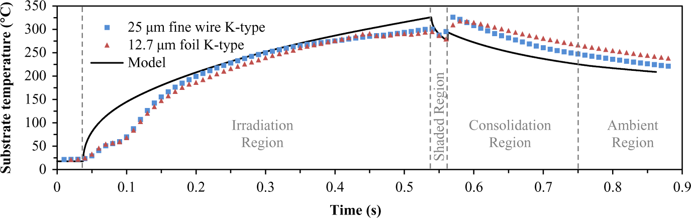
Measured thermocouple data plotted with the model prediction for the default model parameters.
The step in the measured data at the onset of irradiation is most likely due to out-of-focus radiation, however the model assumes uniform intensity on illuminated areas. It is clear that an optical ray-tracing model is required to predict the flux distribution of the laser in order to accurately predict the temperature history prior to the nip point. The sudden drop in temperature in the shaded region prior to the nip point is due to dissipation of the heat away from the surface of the substrate as can be seen in Figure 7. The measurements suggest that this shadow does exist; however, it is hard to confirm, given the limited number of data points in the predicted shaded region.
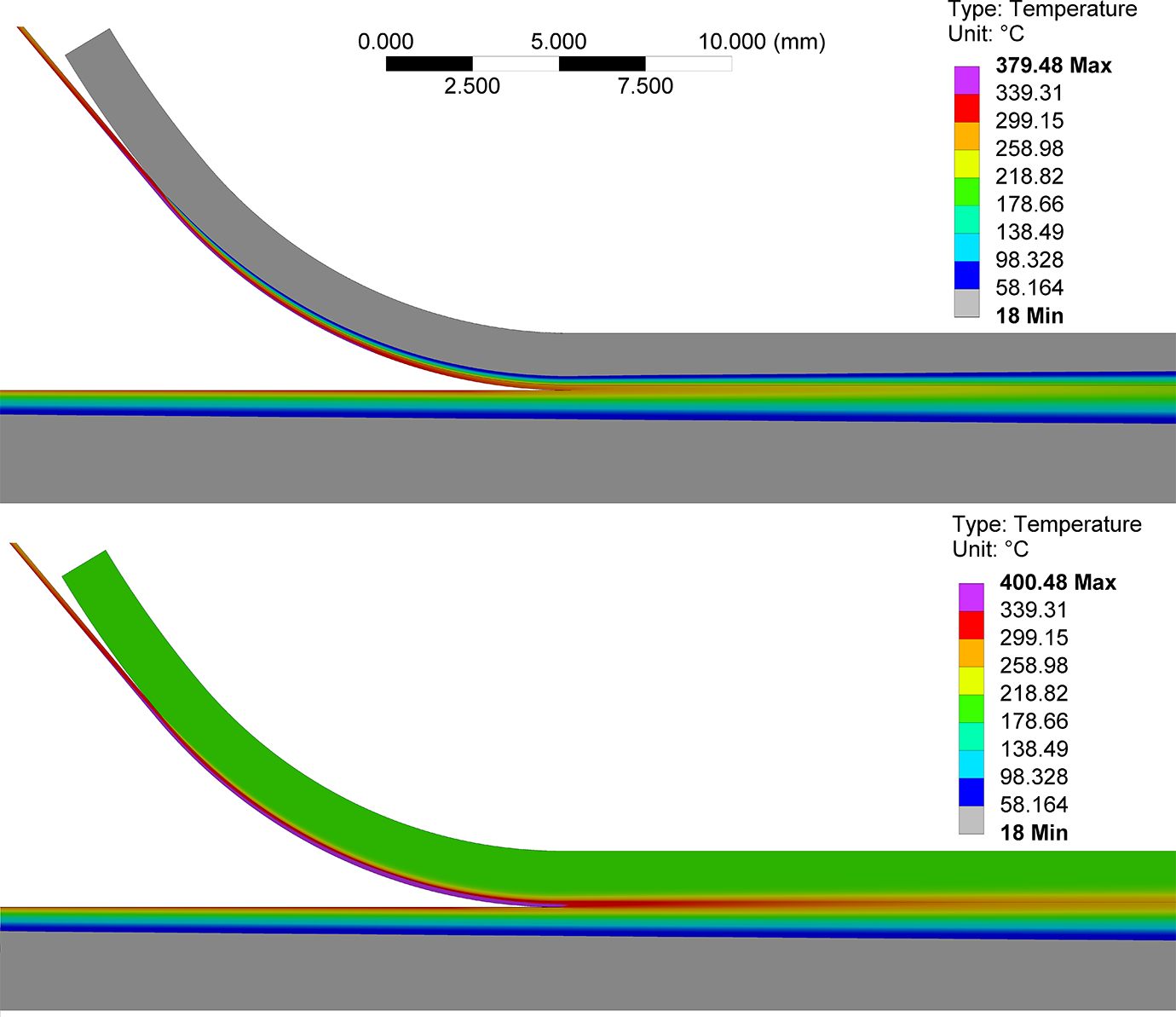
Temperature plots for roller temperatures of 40°C (above) and 200°C (below). Note the incoming tape is heated through the thickness; however, the substrate has a large gradient through the thickness.
Sensitivity analysis
The effect of the roller temperature is shown in Figure 8. It can be seen that higher roller temperatures have two dominant effects. The first is an increase in the incoming tape temperature as there is less heat loss to the roller as the tape approaches the nip point as can also be seen in the temperature plots in Figure 7. This is reflected by the larger discontinuity in temperature at the nip point followed by a higher bond line temperature immediately afterwards. The second effect is the lower rates of cooling on the bond line. This is logical as the heat sink effect is reduced. When comparing only the relative slope of the experimental data with the predictions, it would appear that the roller is at a relatively low temperature in the range of 40°C during the experiments. It is of interest to note that the 300°C roller, while at a higher temperature than half of the consolidation region, it does not impart a heating effect on the bond line. Cooling is dominated by dissipation of heat to the substrate. For every 100°C of roller temperature, there is a corresponding change of approximately 12°C in temperature at the start of the consolidation region.
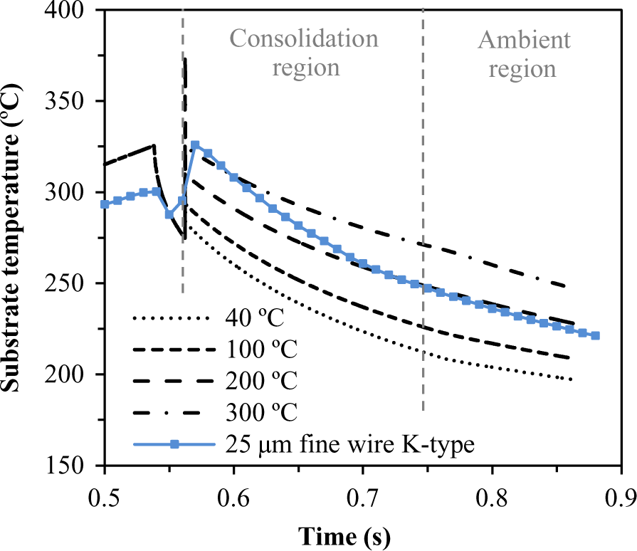
Effect of roller temperature.
Introducing a contact resistance between the composite and the roller has the effect of offsetting the cooling profile upwards as can be seen in Figure 9. The effect of increasing the thermal contact resistance reduces the heat sink effect of the roller, leading to higher tape temperatures. The results show good agreement for a contact resistance in the range of 1.0–2.0 m2.K/kW. This is of the same order of magnitude of a silicone-to-stainless steel interface as reported in literature. 35
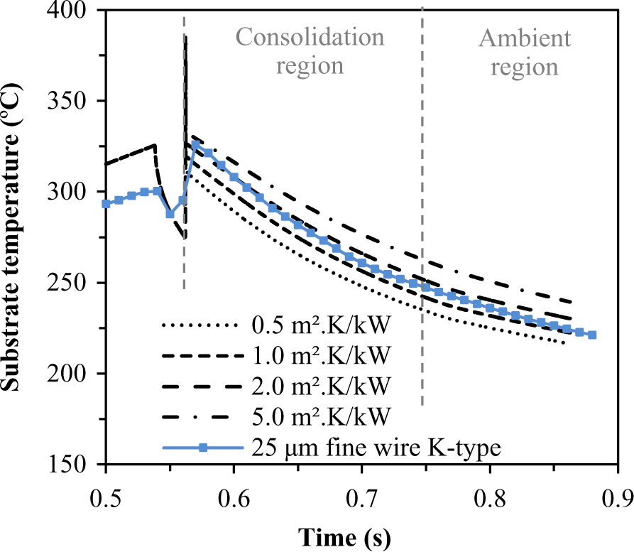
Effect of contact resistance.
The size of the corner radius has a direct effect on the degree of shaded area near the nip point. Decreasing the corner radius results in a smaller shaded region, thus a smaller temperature drop is expected prior to the nip point. Figure 10 shows the modelled effect. It can be seen that a reduction in the corner radius reduces the dip in temperature, leading to higher consolidation temperatures. The model predicts that a reduction in the radius from 15 to 5 mm will result in a 10°C increase in temperature at the nip point, given the default model parameters.
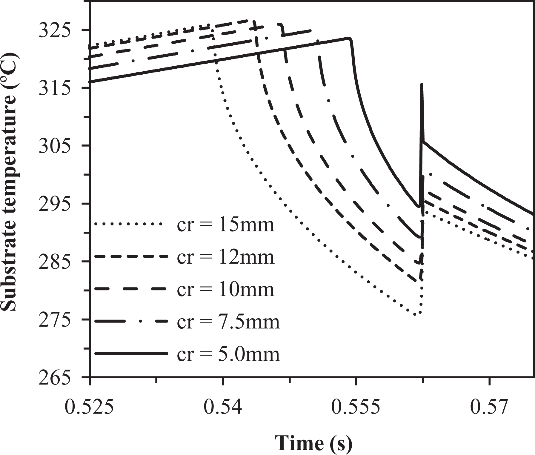
Effect of changing the roller corner radius.
Conclusions and future work
A 2D finite element thermal model incorporating the mass transport of heat was formulated for a laser-assisted thermoplastic tape placement system using a conformable consolidation roller. It was found that the roller geometry could be significantly reduced due to a combination of the low thermal diffusivity of the roller elastomer and relatively fast mass flows.
In situ temperature measurement was successfully performed using a fine wire K-type thermocouple. The model was compared with the thermocouple measurement and found to correlate reasonably well, particularly in terms of timing of the heated, shaded, consolidation and cooling regions with respect to each other, however experimental temperature measurements imply higher tape temperature than that of the modelled. The model predicts a relatively uniform temperature distribution through the thickness of the incoming tape; however, a significant temperature gradient is present through the thickness of the substrate due to the dissipation of the heat. The presence of the shaded region results in significant cooling of the surface prior to the nip point, particularly on the incoming tape. This suggests that significant overheating is required in order to achieve the necessary nip point temperatures for bonding.
The effects of roller temperature, corner radius and thermal contact were studied using the model. The temperature of the consolidation roller was found to have a significant impact on the cooling rate at the bond line and also the temperature of the incoming tape. Increasing the thermal contact resistance was found to have a reasonable influence, with the main effect of raising the incoming tape temperature due to a decreased heat sink effect from the roller. The model assuming 2.0 m2.K/kW had good agreement with the measured data. Reducing the corner radius of the consolidation roller was found to slightly bias the heat towards the tape as well as a small increase in the temperature at the nip point.
Future work includes measurement of the tape and roller temperature during the process and determination of the thermal contact resistance. Further experiments should be performed at a range of process speeds and temperatures so that the model can be validated for a wider range of process conditions. Temperatures should be measured at a higher sample rate in order to confirm the presence of a shaded region. Implementation of an optical ray-tracing model can be used to better estimate the heat flux distributions due to the laser, leading to improved temperature prediction in the region prior to the nip point.
Footnotes
Declaration of Conflicting Interests
The author(s) declared no potential conflicts of interest with respect to the research, authorship, and/or publication of this article.
Funding
The author(s) disclosed receipt of the following financial support for the research, authorship, and/or publication of this article: This original research was proudly supported by the Commonwealth of Australia, through the Cooperative Research Centre for Advanced Automotive Technology (AutoCRC). The support of AFPT GmbH for the provision of experimental facilities and human resources is greatly acknowledged.