
Abstract
Mechanical properties and deformation mechanism of polypropylene (PP) filled with different weight percentage of ethylene–octene copolymer (EOC) and fibrillar silicate attapulgite (ATP) clay were investigated under uniaxial cyclic loading at constant crosshead speed to evaluate plasticity/damage coupling behavior. With increasing EOC and clay content, PP exhibited typical plastics response with marked stress drop at yield followed by steady state plastics region up to rupture. The addition of 3 wt% ATP clay to the PP/EOC blend shows enhanced impact strength up to four times compared to PP with decrease in yield strength by 24% implied synergistic toughening effect. Volume strain, which characterizes deformation damage, steadily increased over the whole plastics stage up to 5.2 for axial strain of 0.30 after a critical tensile strain of 0.05. The small energy value observed for large volume strain revealed matrix shear deformation as the controlling factor for energy dissipation without crazing. Fractography observation using scanning electron microscopy revealed formation of debonding and cavitations on the surface of PP matrix, contributing increase in the volume of all compositions.
Introduction
The performance of polyethylene increases with α-olefin branch length. The longer branches of the octene comonomer are believed to result in a larger fraction of tie molecules in the interlamellar region. 1 Bureau et al. 2 found that as the length of the comonomer unit increases, the mechanical properties of the polymer also improve. Unlike ethylene-containing elastomer, octene comonomer is excluded from the ethylene crystal lattice resulting in improved mechanical performance. For thermoplastic applications, the ethylene–octene copolymer (EOC) imparts good toughness, clarity, and elasticity. For impact modification, the EOC delivers stiffness, toughness, and excellent processability. 1 –5 EOC offers thermal stability, electrical properties, and low Mooney processing with high Mooney performance. 5 Low-crystalline EOC copolymers, those with 7–20 mol% comonomer, exhibit elastomeric behavior at ambient temperature with low initial modulus, uniform deformation to high strains, and high recovery after the stress is released. At present, the impact strength of polypropylene (PP) can be improved up to four times with the addition of EOC elastomer. 6,7 Several reviews have been devoted for studying the toughening mechanism of elastomer-modified PP blends. 8 Da Silva and Coutinho 3 reported influence of the blending process on the relationship between morphology and final properties of PP/EOC blend systems including rheological, mechanical, thermal, and morphological properties. The mechanical analysis depicted that PP/EOC with 30 wt% of EOC enhanced toughness behavior. 3 Carriere and Silvis 4 investigated the effect of short-chain branching and comonomer type on the measured interfacial tension of PP/EOC blends using the imbedded fiber retraction method. The short-chain branches were controlled by systematically increasing the octene level in the EOC materials produced from ethylene–octene comonomers. The interfacial tension was found to decrease monotonically with increasing octene content, resulting in greater compatible PP/EOC blends. Lim et al. 5 and Paul and Kale 9 found that the impact properties of PP copolymer can be significantly improved by blending with 10–20 wt% EOC copolymer. Paul and Kale 9 also proposed that the presence of the ethylene phase in EOC copolymer may have improved the compatibility of EOC with PP copolymer. Therefore, the EOC elastomer could be more suitable for PP copolymers compared with polyethylene.
The rubber-rich EOC blends behave like ideal elastomers with distinctly low elastic modulus. It is of particular interest to investigate the structure–property of rubber-rich thermoplastic olefin blends reinforced with rigid nanofillers. Due to the addition of elastomer, the stiffness and yield strength of PP/EOC blends are lower than those of the pure PP. Therefore, conventional microfillers have been used to restore the mechanical strength of PP/EOC blends. So far, various fillers like talc, 10,11 calcium carbonate, 12,13 and kaolin 14 have been employed to increase stiffness of rubber-toughened PP blends.
Attapulgite (ATP) is a hydrated magnesium aluminum silicate present in nature as a fibrillar mineral. ATP is fibrillar single crystal with a length of 500–2000 nm and a diameter of 10–25 nm. 15 The interaction of ATP crystal is extremely small due to line–line contacts, which result weak interaction and facilitate separation of ATP agglomerates into single crystal on application of large strain. Modification of ATP with Si–OH, after being hydrolyzed by silane, reacts with hydroxyl group of ATP to improve adhesion of ATP. ATP could also be separated into nanosized fibrils with high aspect ratio, showing affective reinforcement. 16,17
There are strong indications that the use of ATP clay as reinforcing particle in elastomers drastically improves many of their mechanical properties and gives composites superior to those based on isometrics filler particles. 18 The mechanical properties of PP nanocomposites were improved by the addition of ATP. In addition, the incorporation of organophilic ATP (org-ATP) also gave rise to a considerable increase in the storage modulus demonstrating the reinforcing effect of clay on the PP matrix. 18 In addition, the incorporation of org-ATP also gave rise to an increase in the storage modulus and the changes in the glass transition temperature for PP composites. 17 The high aspect ratio of the ATP fiber makes it extensively used in polymer composites. 18,19 Gao et al. 16 studied the preparation and properties of PP filled with modified ATP using silane. 18
Major theory associated for toughening mechanism and deformation behavior of PP/EOC blends are multiple crazing, shear yielding, formation of dilation bands following rubber cavitation and debonding. Dilation band associated when voids propagate by repeated cavitation. For further studies on deformation mechanism, scanning electron microscopic study was used. Macroscopic properties of these blends and composites depends on several key parameters like blend composition, size, shape, and distribution of dispersed particles, interparticle distance, and interparticle adhesion between dispersed particle and matrix. Under external loading, elastomers act as stress concentrators to nucleate plastic deformation by relieving hydrostatic pressure upon stretching, create cavitation and multiple matrix crazing, 19 shear yielding, 20 and crazing. 21 EOC could not extend into infinite stretch ratio, as damage is associated at large strain. Cavitation in composite plays an important role in improvement of toughness in ATP-modified PP/EOC matrix. Cavitation occurs when stress level is sufficiently high such that void expansion is large. 22 Cavitation initiated from flaws that grows due to hydrostatic tensile stress, and ahead of crack, stress exist in different directions. 23,24 Filler addition and strain application lead to rubber hardening, which happens due to chemical and physical interaction between filler and macromolecular chains of rubber. Depending on bond type between filler and matrix, softening is associated with particle–rubber interaction. The hysteresis losses are the main feature for softening. By calculating hysteresis loss with growing strain of elastomer, contribution of different mechanism can be calculated that cause volume change of rubber. 22 Energy loss is attributed due to viscoelastic characteristics of rubber. Part of energy dissipated is spent on elastomer deformation. The reason associated for energy dissipation is deformation of unmovable segments and failure of filled elastomer structure.
The study on the mechanical behavior of PP/ATP/EOC elastomer blends was conducted principally by putting the emphasis on the reinforcing and toughening effect. A domain until now not explored widely and deeply is the plastic deformation behavior of ATP-reinforced PP/EOC composite and corresponding damage mechanisms. The plastic deformation can be produced by two mechanisms: shear banding and cavitation. The latter can result in a volume expansion of the samples deformed. Therefore, volume change is considered to be a phenomenon accompanied with the plastic deformation and damage in polymer blends. Bucknall and Smith 25 studied the dilatation of high-impact polystyrene under creep tests by measuring the dilatation with a special extensometer. The accumulation of plastic damage under cyclic or fatigue loading is seldom studied. The crazing, microvoid formation, and lamellae alignment were found to vary with increasing amount of true strain and number of cycles. Many studies 26,27 contributed to hysteresis loss and softening of elastomer. But, studies related to volume change, energy dissipation, and damage mechanism using uniaxial cyclic loading are much less.
The residual strain after each loading–unloading cycle increased with increasing applied strain. In this article, the plastic damage behavior of PP/ATP/EOC blends under cyclic tension is investigated. The true stress–strain behavior, volume variation, and energy dissipation are measured in the present study. The plastic damage mechanisms were revealed with scanning electron micrographs (SEMs). The results obtained are helpful to understand the mechanical behavior of polymer blends under large deformation.
Experimental
Materials
PP copolymer PP 401 of density 0.96 g/cc and melt flow index 12g/10 min was supplied by Reliance Petrochemicals (Ahemedabad, India). The impact modifier, EOC grade Engage 8150, was supplied by DuPont Dow Elastomers (Wilmington, Delaware, USA). Its octene content and melt flow rate were 25 wt% and 0.5 g/10 min, respectively. ATP nanofibrillar clay with an average diameter of 20 nm was provided by 20 Micron Limited (Vadodara, Gujarat, India). γ-Aminopropyl triethoxysilane (APS) was supplied by Evonik Degussa GmbH Inorganic Materials (Essen, Germany). All other chemicals are procured from Sigma-Aldrich (Bangalore, India) and used without any modification.
Silane treatment for ATP clay
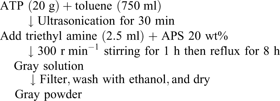
A 20-g nanoparticle of ATP clay was kept in vacuum chamber for 24 h at 100° and then dispersed in 750 ml anhydrous toluene with the aid of ultrasonication for 1 h. After ultrasonication, 2.5 ml of triethyl amine as catalyst and 20 wt% (2 ml) of APS were added, respectively, with constant stirring at 300 r min−1 for 1 h. The mixture was then refluxed for further 8 h under nitrogen atmosphere. Modified particles were filtered under suction and physically adsorbed APS compound on the modified surface of nanoparticle were washed with ethanol for 4–5 times. The nanoparticles were finally dried in low pressure oven at 80°C for 12 h.
Modification of ATP clay by APS is given as follows
Processing of blends and nanocomposites
PP, EOC, and treated ATP clay were first vacuum dried at 80, 60, and 80°C, respectively, for 4 h. All blends and nanocomposites containing PP and EOC with or without nanofiller were compounded using microcompounder (DSM Xplore, Geleen, the Netherlands) at 40 r min−1 screw speed maintained at a constant torque level of 80 Nm and temperature of 180°C from feed zone to die zone with 10 min time duration in all case. The first series of PP with EOC blends were obtained at level varying from 10 to 40 wt% of EOC in the PP matrix. ATP was incorporated as nanofiller to the optimized blend at different weight percentage. Table 1 represents various compositions prepared for this investigation and their designation used. All tensile and impact samples were prepared by injection molding machine (DSM Xplore 12, Germany) at 190°C zone temperature and 40°C mold temperature.
Composition of polymer blend and composites.
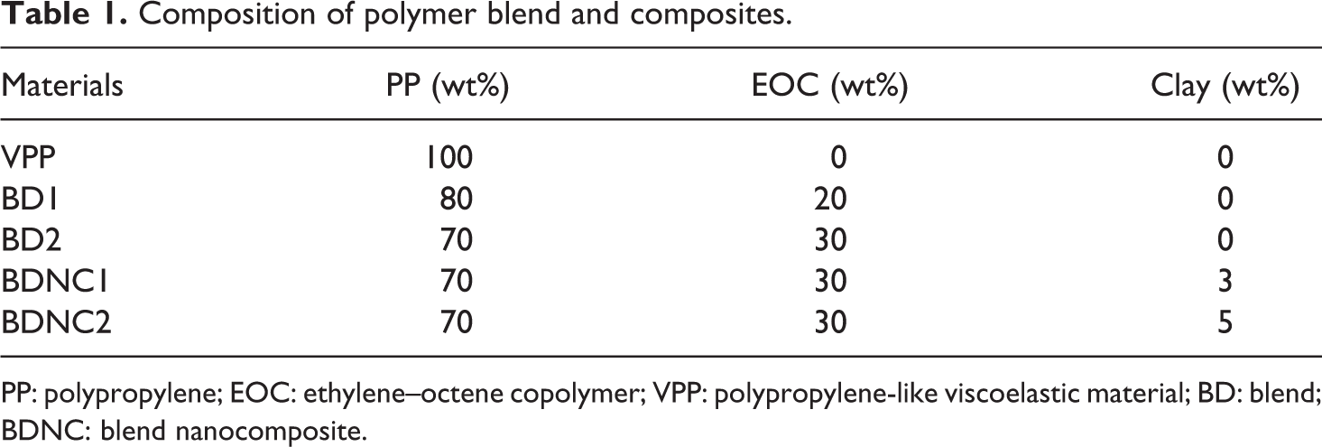
PP: polypropylene; EOC: ethylene–octene copolymer; VPP: polypropylene-like viscoelastic material; BD: blend; BDNC: blend nanocomposite.
Test configuration
All tensile tests were performed using universal testing machine (UTM; model 3382, Instron, Norwood, Massachusetts, USA). Video traction system was utilized to measure the deformation of the tensile specimens for every 30 s. Figure 1 shows the picture of the test setup. The measurements of the strain were accomplished with the help of seven markers on the surface of the specimen. All the marks are blue in color, nearly round with a diameter of about 10 mm. Five markers (A, B, C, D, E) were aligned along the longitudinal axis, and the remaining two markers (F, G) were aligned along the transverse axis. Markers in the transverse axis are separated in such a way that they occupy major fraction of the total width of the specimen. All the markers are separated by 2.5 mm.
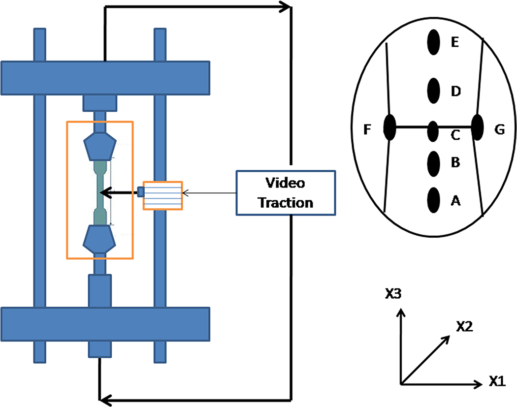
Configuration of video traction system.
Testing procedure
Tensile tests were carried out using UTM machine following ASTM-D638 standard test method at 24°C. The crosshead speed was 10 mm min−1 during tensile loading process. Stress–strain curves were recorded until fracture for all the specimens. To study the cycling load effects on the tension fracture behavior of the polymers, a series of tension–tension loading cycles (five cycles) are applied to all specimens during tensile loading. Cyclic tests were carried out with a strain-controlled way according to the following program: (1) loading with constant crosshead speed up to the maximum strain; (2) retraction with the same crosshead speed down to minimum strain; and (3) subsequent reloading and retraction has been carried out. The loading was interrupted when true strain reached a maximum value (ε max) at 0.25 with constant crosshead speed of 10 mm min−1 corresponding to a nominal strain rate of 0.033 s−1. Each test involved N = 5 cycles of loading–retraction (tests with ε max = 0.25) with preloaded specimen up to 0.5 N to avoid buckling when stresses at retraction became negative. The interval of maximum strain ε max covered entire length of subyield and postyield region of deformation. The permanent deformation of the material increased with the number of cycles. Cyclic test has been carried out for all rectangular specimens with a cross section of 8 × 4 mm2 size each.
Components of volume strain
The expression of volume strain for three principal strains can be written by Hencky formalism as follows
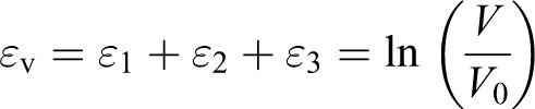
where V and V o are the initial and final volume of representative volume element (RVE), respectively. The strain components and the volume strain are associative. In the notation, number indicated applied direction of measurement where ε 1 is the longitudinal strain applied in x 1 direction and ε 2 and ε 3 are transverse strains applied in x 2 and x 3 directions, respectively.
Impact test
To evaluate the impact energy of the material, notched impact test was conducted (Tinius Olsen, Horsham, Pennsylvania, USA) as per ASTM-D256. Hammer energy of 20 J with 3.5 m s−1 striking speed of pendulum was used. Minimum of four samples were tested, and the average result was reported.
Scanning electron microscopy
The surface morphologies, failure mechanisms, and phase structures of the fractured specimens were examined using a scanning electron microscope (model EVO 60, Zeiss, Berlin, Germany) at an acceleration voltage of 30 kV. The samples were coated with gold using a vacuum sputter coater prior to test to improve the surface conductivity. Average domain sizes of discarded phase were calculated. It is carried out in the conditions of temperature well below the room temperature and source of accelerated voltages (2 kV) in order to prevent damage to single polymer crystals. The impact bars of nanocomposites were cryofractured parallel to the melt flow direction to produce brittle fracture surfaces that were subjected to platinum sputter coating.
Results and discussion
Uniaxial tensile stress–strain deformation behavior
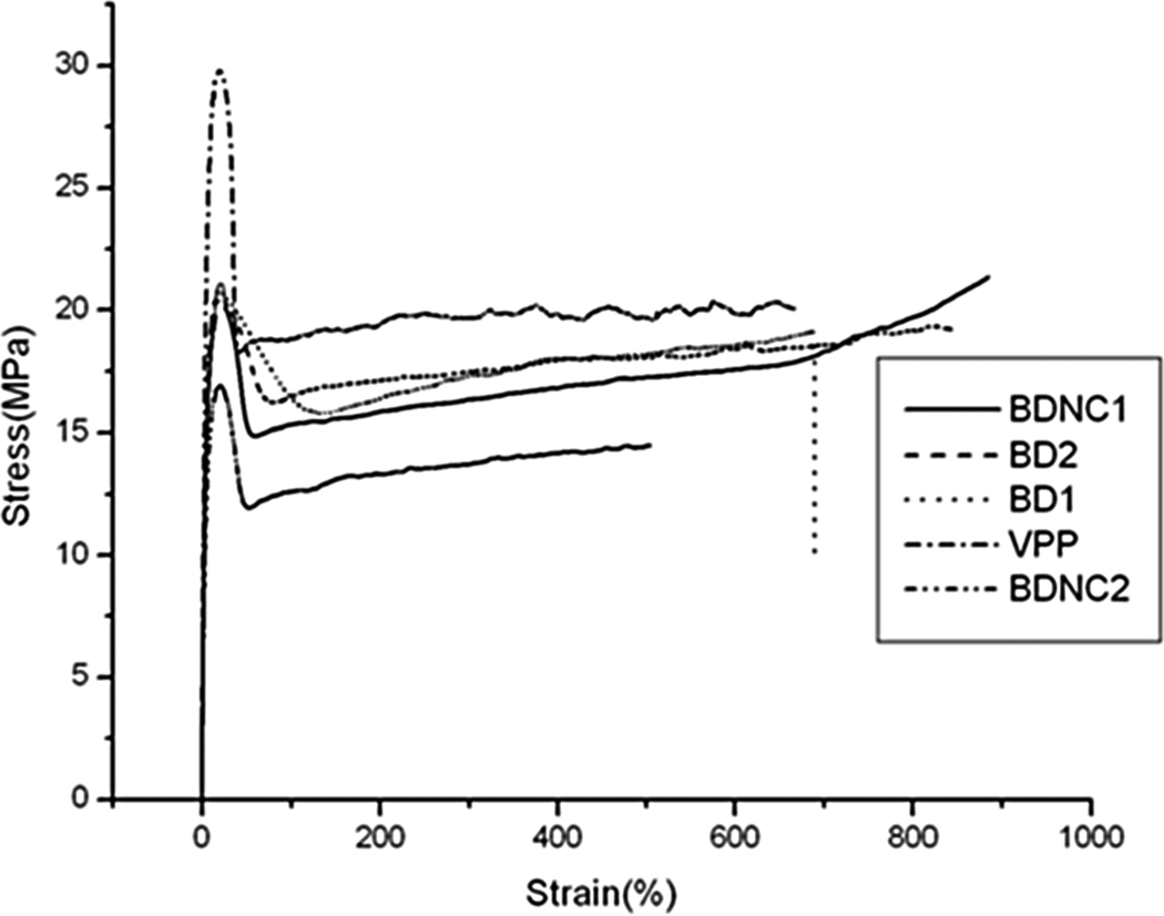
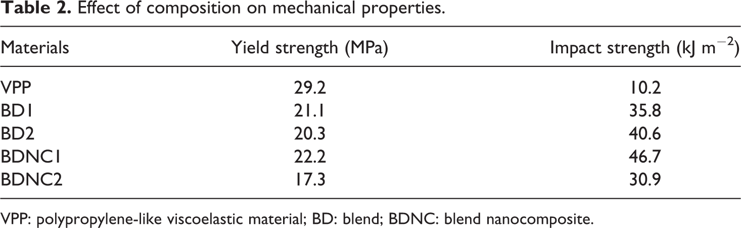
Uniaxial stress–strain behavior of neat PP and PP/EOC blends with varying concentrations of ATP clay is illustrated in Figure 2. Yield strength value for all the compositions is depicted in Table 2.The neat PP (51 wt% crystalline in this case) is our reference material. After reaching the yield point about σ y = 29 MPa, it exhibited significant drop of true stress followed with strain larger than about 600%. Progressive decrease in yield strength was observed with effect of strain hardening that followed immediately after the yielding for all the binary blends and ternary composites. Decrease in yield stress for BD1 (80/20) and BD2 (70/30) blends is around 27% and 30%, respectively, compared with PP followed with formation of necks occurred. The reason may be attributed due to droplets of EOC dispersed in the PP matrix are too weak to sustain stress of continuous phase. Sudden stress drops at yield point for all compositions observed due to strain softening of the PP matrix in the presence of EOC particles. With increase in strain, EOC particles undergo stretching on application of load. The strain softening of all the composition may be caused due to the presence of elastomeric phase and growth of microvoids in the materials. On the contrary, the strain hardening is the result of growth of nucleation and shear banding of the matrix. The same results were also found by Bai et al. 1 in PP/EOC/polyamide 6 (PA6) blends. From Figure 2, the stress–strain behavior of BDNC1 (70/30/3) blend nanocomposite is quite similar to BD2 because of the presence of similar weight percentage of elastomer at low clay content (3% ATP). Reinforcement of BD2 with ATP clay nanofiller increased yield stress value up to 5 and 9%, respectively, compared to BD1 and BD2 blends.This may be due to the inclusion of ATP, which may enhance the adhesion of rubber particles to the ATP surface forming encapsulation structure. Also, this may be due to the result of Si-OH silane coupling agent; after hydrolysis, it could react with ATP. There is a decrease in surface energy of ATP with enhancement of adhesion between EOC and ATP. 17 This attributes ATP as single crystal in the PP/EOC matrix maintaining high aspect ratio with pronounced reinforcement effect to sustain stress. The further growth of filler content (5% ATP) depicted decreased yield stress by 30% and 14%, respectively, followed by reduced elongation at break compared to all compositions. This is due to the dispersion of ATP as separate units in the matrix that may contain voids due to cavitation under shear force giving unfavorable oriented structure. This dispersed unit tends to agglomerate in the matrix due to their huge surface area, which results in decrease in stress upon stretching. 28
True stress–strain relationship under uniaxial loading.
Effect of composition on mechanical properties.
VPP: polypropylene-like viscoelastic material; BD: blend; BDNC: blend nanocomposite.
Strain-induced behavior
Figure 2 illustrates the evolution of true axial stress–strain behavior with a constant true strain with crosshead speed of 10 mm min−1. The shape of first stress–strain curve in the steady state plastic regime seemed to be very sensitive to the material composition. A gradual increase in slope was observed for all compositions in the plastic stage at large strain under uniaxial tension.
The neat PP exhibited a moderate softening with sharp yield point of about 29.2 MPa and large strain up to 600%, increasing gradually with progressive hardening up to rupture. The mechanical response of the BDs under monotonous stretching is characterized by a marked yield drop at the elastic limit, while a neck is developed as the geometric defects. It is worthy to notice that the stress decreases after the yield, about 5 MPa for BDs and BDNCs. This phenomenon corresponds here to strain-induced softening of BDs and BDNCs. Wang and his colleagues 29 observed similar results for PP/PA6/EOC blends with decrease in stress after yield. This may be due to the presence of EOC particles in PP matrix that contributes to strain softening. Large size of elastomer domain and poor adhesion lead to macrovoiding in elastomer-rich region, which leads to rubber-like elongation beyond yield stress. This results in extensive stress whitening without development of localized necking. After the yield drop, it gets stabilized at a strain of about 35%, after which a long plastic stage is observed that extended until up to rupture without much increase in stress. This may be due to the involvement of slip of the spherulitic crystal blocks past each other followed by homogenous arrangement of crystals that make irrecoverable plastic deformation with manifested sharp necking. 30,31 During stretching, shearing occurred, and fragmentation of crystals was rearranged in to oriented microfibrils. All the BDs and BDNCs showed the same deformation stages including short viscoelastic behavior at a strain lower than 35%, followed by yield. This stage begins a quasi-horizontal plateau and then increased strain hardening in the plastic deformation stage. This continues at a large accumulated strain between 600 and 850% (i.e. 6–8.5). This Hencky strain is corresponded to local extension ratio. It is worthy to note that BDNC1 (70/30/3) blend nanocomposite showed higher hardening at large strain because the long chain orientation is small so that the flow stress attained nearly up to 20.5 MPa without rupture. This result was due to critical interfacial adhesion of ATP clay that might be strong enough to increase interaction, facilitating shear yielding of PP/EOC matrix. Reduced elongation was observed for BDNC2 because of the presence of microvoids, resulting in unfavorable oriented structure. These voids will be stretched along the shear yielding matrix leading to failure of samples at lower value of stress and elongation.
True axial stress–strain behavior under cyclic loadings
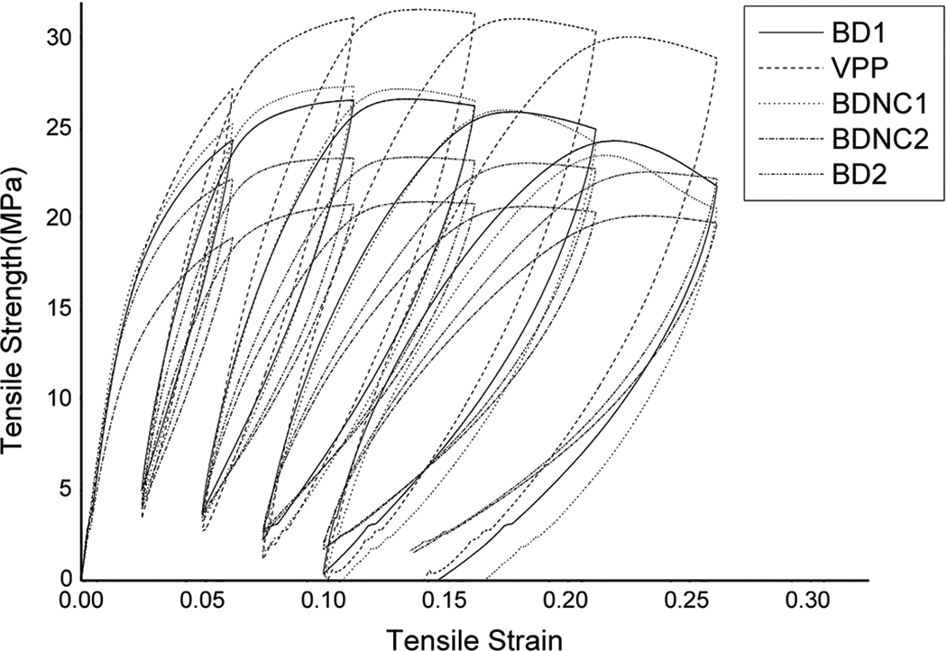
Figure 3 shows the distribution of five cycles of static tension compression loadings on specimens at constant strain with crosshead speed of 10 mm min−1. It is observed that the area included in the hysteresis curve for all compositions increases with the increasing number of loading cycles. This means that the stability of blends for damage is high with the increasing number of loading cycles. Accumulation of damage proceeds with subsequent loading and retraction but with decreasing intensity. This is due to diminishing effect of “weak” lamellae with time due to their breakage.
True stress–strain relationship under cyclic tension.
The presence of PP-like viscoelastic material (VPP) in all compositions attributed the decreased stress part ascribed as damage and the stress relaxation part as experienced.
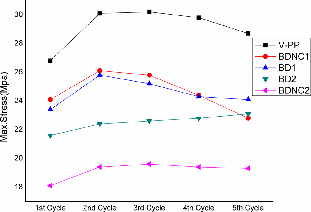
Figure 4 and Table 3 show maximum stress in all five cycles for all compositions. Table 3 represents progressive decrease in maximum stress of BD1, BD2, and BDNC compounds in comparison with neat PP. A progressive decrease in maximum stress with alloying content in blends is remarked by Bureau et al. 2 From Figure 3, the following observations are concluded. First, there was an increase in modulus in the first stage corresponding to elastic limit (up to two cycles) indicating a cyclic hardening phenomenon and then progressively decreasing modulus with increasing cycle, indicating cyclic softening phenomenon. Nonlinearity in stress–strain relation can be observed here. Such similar nonlinearity and decrease in modulus are observed in uniaxial fatigue tests of the PP/ethylene–propylene–diene monomer blends. 32 After the second cycle, the rate of modulus of VPP, BDNC1, and BD2 slows down as the number increases. The reason may be due to the breaking of molecular bonds and sliding of entangles, which may cause collapse and deteriorates the load-carrying capacity. These needs are further verified with SEM. According to Soliman et al., 33 this deformation is due to the presence of PP that undergoes yielding and buckling by recovering tendency of rubber particles. Upon stretching, PP acts as glue between the EOC and clay particles, and part of PP fraction undergoes yielding with partial pull back during recovery. It is clear from Figure 3 and Table 3 that hardening occurred for first two cycles followed by softening for the rest of the cycles. Furthermore, comparing the hysteresis behavior of two material classes, BDNC1 and BD2, it is observed that BDNC1 exhibited higher modulus and yield strength combination with lower energy loss. It may be due to the physical reinforcement of ATP clay with higher chain entanglement density. Figure 4 shows increase in maximum stress and modulus of BDNC2 blend nanocomposite and BD2 for each cycle with increasing strain. However, the value is much lower compared to BD1 blend and BDNC1 blend nanocomposite. The rate of stress range is higher with the increase in strain. The evolution of stress range during cyclic loading is due to competence between modulus drop and decrease in nonlinearity of the stress–strain relation. In these tests, the effect of modulus drop is more severe than the decrease in nonlinearity of stress–strain relation, resulting in the phenomenon of cyclic softening.
Maximum stress for each cycle.
Result of cyclic loading at constant strain.
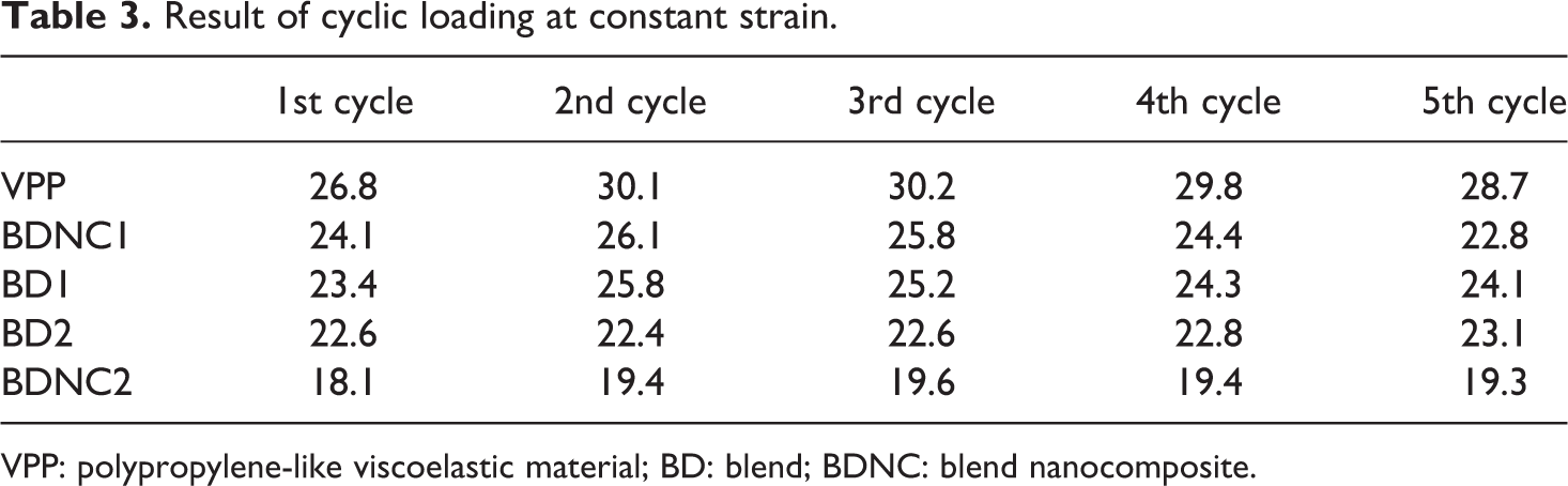
VPP: polypropylene-like viscoelastic material; BD: blend; BDNC: blend nanocomposite.
Impact strength
Table 2 depicts variation in the impact and yield strength values for same compositions. A substantial improvement in impact strength observed for BD1 and BD2 blends by 71 and 75%, respectively, is higher compared to PP. No failure was observed for the above compositions, which implies synergistic toughening effect. Under external loading, elastomer domains act as stress concentrators to nucleate plastics deformation by releasing hydrostatic pressure upon stretching and create cavitation and multiple matrix crazing. Improvement in toughness depends on several parameters like blend composition and shape, distribution of dispersed particles, interparticle distance, and interparticle adhesion between dispersed particles and matrix. Significant effort was made to study the toughening effect using SEMs. It could be seen from Figure 5 that the addition of EOC in the PP matrix showed pronounced improvement in impact resistance, which was consistent with the results as reported. 32 For BDNC1 blend nanocomposite, increase in the impact strength by 78% was observed as compared to neat PP at 3 wt% of clay loading into the PP/EOC matrix. This implied synergistic toughening effect by addition of clay into the PP/EOC matrix with formation of encapsulation may be due to better interfacial interaction and unique molecular micro strength with PP/EOC phase. Impact strength of BDNC1 blend nanocomposite was enhanced by four times compared with PP and two times compared with BD2 with decrease in the yield strength by 7 MPa. This result demonstrates balanced mechanical property of BDNC1 blend nanocomposite with controlled strength and toughness.
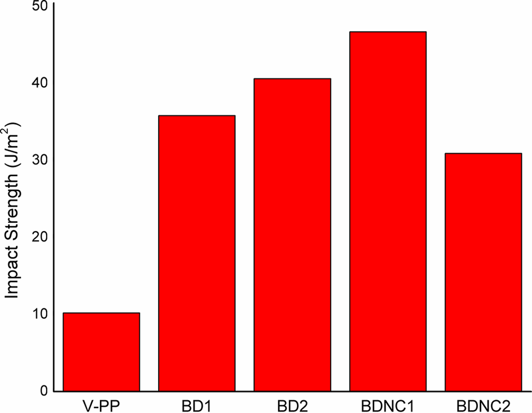
Impact strength of the composite.
Volume strain
The volume strain is defined as
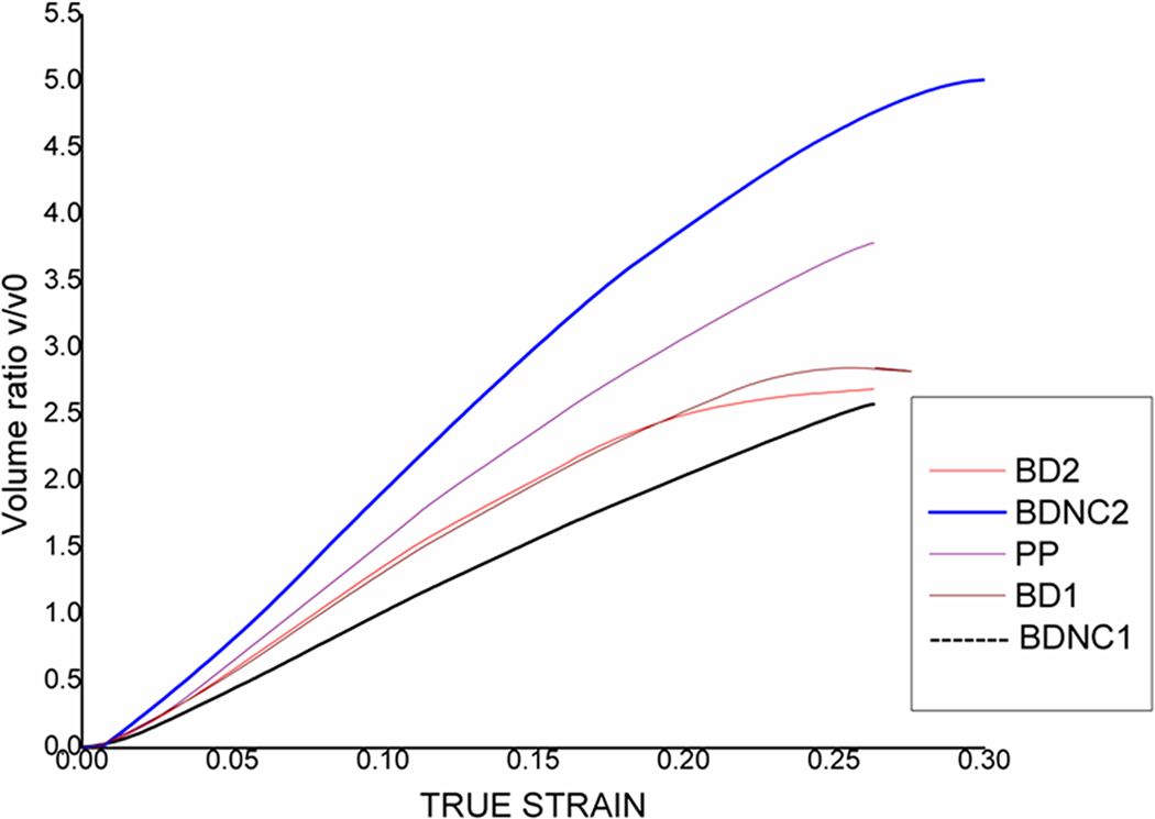
Volume strain versus true strain under cyclic tension.
Energy dissipation
Figure 7 shows the total energy density versus applied true strain during loading and unloading cycle under cyclic tension. Here, energy density means energy per unit volume. The elastic energy (E c) and the plastic energy (E p) are combined to form the total energy density. After unloading to zero load, E c is reduced. Area of the hysteresis loop gives direct measure of total energy density per one loading/unloading cycle. Total energy for all composition increased. The aberration of the curves of blends and composites are larger and larger with increase in true strain. BDNC1 (70/30/3) blend nanocomposite shows comparatively higher energy density compared to BD1, BD2, and BDNC2 composition. Matrix shear banding and cavitations are the two main important parts of E p. During loading process, elastic deformation, plastic deformation, and internal heat supply can raise the temperature of the samples. Figure 7 represents total energy absorbed is not much different for the materials, at the deformation stage with strain below 0.05, which is an agreement with Jiankang et al. 37 However, with increasing the true strain, the increase in total energy density of neat PP, BD2, and BDNC1 is observed. The improved property can be explained by the fact of better interfacial adhesion between clay and matrix. Lower energy density for BD1 and BD2 blends may be associated due to debonding with higher chain entanglement density. Total energy density of PP is higher compared to all composition. For neat PP, damage associated with nucleation occurs between lamellae of spherulite crystals. From Figure 7, variation in energy density at higher strain signifies different deformation mechanism for all blends.
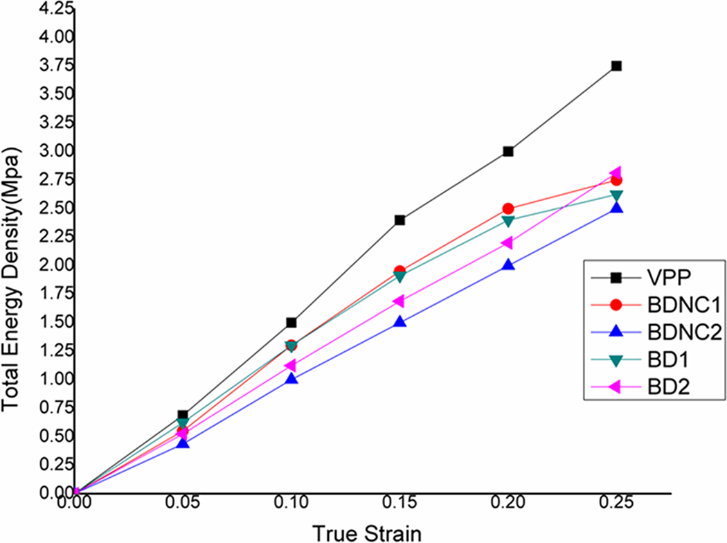
Total energy density versus applied true strain for cyclic tension.
From Figures 6 and 7, it is noted that large volume strain comes from the abundant nucleation and growth of cavities inside samples, which corresponds to small energy dissipation such as in the case of BDNC2. The small energy value with large volume strain, that is, the energy dissipation comes mainly from the matrix shear deformation, instead of cavitation. Therefore, we have to conclude that the matrix shear deformation is the controlling factor for energy dissipation without crazing.
Scanning electron microscopy
Mechanism of crack growth and fractographic observation
Toughness mechanism of BD1, BD2, BDNC1, and BDNC2 are studied by SEMs of impact fractured surface as shown in Figures 8 to 11, respectively. Crack propagation behavior of neat PP is in a stable manner in its own plane as evident from stress–strain graph. Presence of some fibrils due to its lamellae structure is not able to arrest the crack growth. 38
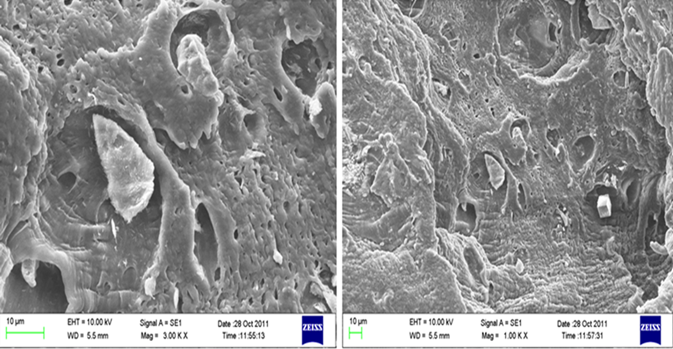
Impact fracture morphology of BD1 at low magnification and high magnification.
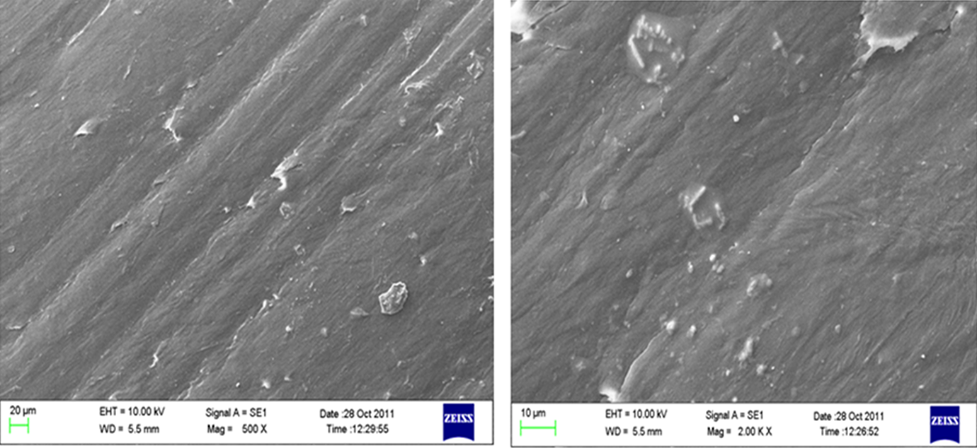
Impact fracture morphology of BD2 at low magnification and high magnification.
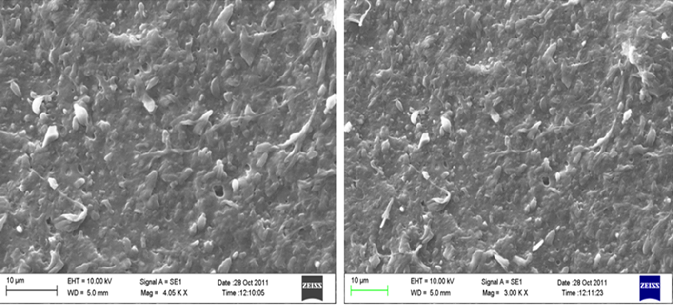
Impact fracture morphology of BDNC1 composite at low and high magnification.
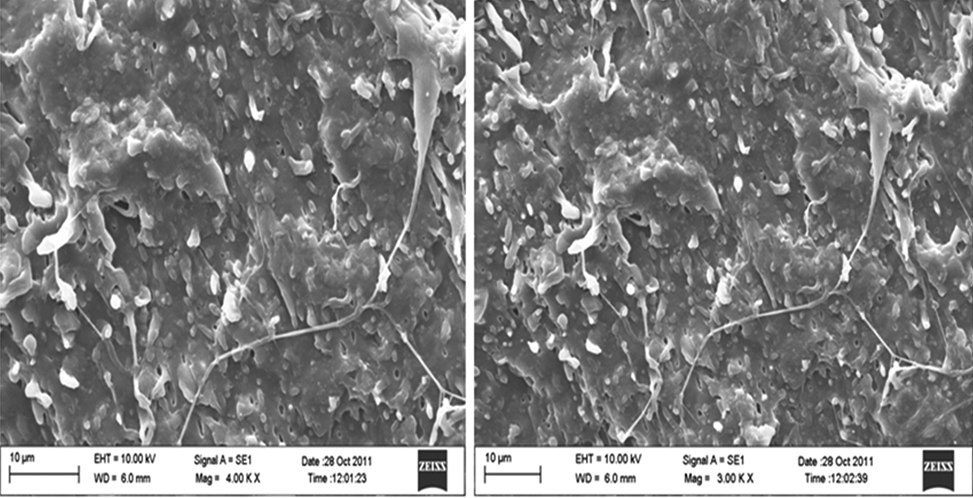
Impact fracture morphology of BDNC2 composite at low and high magnification.
As shown in Figure 8, great deal of crazing was observed with tearing pieces on the fractured surface of BD1 (80/20) blend. Also, some nano-sized fibril structure due to neat PP is observed on the surface that is not capable to arrest the crack growth propagated in its own plane in an unstable manner. After a considerable amount of drawing, crack initiation took place at the initiation site, which shows fibrillar structure. Similar result is also found in PP/EOC blends.32 Shear yield proceeds deformation in the propagation zone. The propagation zone has two different regions, a narrow stable crack growth region and an unstable crack growth region. The narrow stable crack growth region lies immediately after the initiation site. The unstable crack growth region has cleavage type fracture in the middle and thread-like fibrils along the edges. Cleavage is associated with bright reflecting facts in the specimens.
In the BD2 (70/30) blend, the crack is not able to propagate in its own plane and there may be evidence of excessive fibrillation in the plastically deformed regions before fracture. This is clear from SEM images of fractured specimen, which is shown in Figure 9. The crack is nearly blocked for propagation by large-sized fibrils, which is also reported by Saminathan et al. 38 EOC-impregnated fibrils induced high strength having capability of arresting the crack from propagation. This situation led to void initiation at the location of submicron-sized particles that may be bonded to the matrix. 39 Figure 9 shows fibrils bridging two voids. This observation indicates that fracture occurs by void initiation at submicron size rubber particles, which are well bonded to the matrix. The propagation zone has layered structure, which is in the perpendicular direction to the propagation zone.
Large number of microvoids grows in BDNC1 (70/30/3) blend nanocomposite, until blocked by impregnated fibrils as shown in Figure 10. Presence of microvoids observed in the damage zone was visible to the naked eye as surface whitening. These voids change its shape growth along weak location in the impregnated fibrils. Then, it breaks the fibrils and propagated further. This type of crack propagation in BDNC1 nanocomposite is irregular. Hence, this type of crack propagation needs more energy, consequently, improving the specific essential work of necking. Most microvoids are due to cavitation of ATP particles, although some particle debonding was observed. This may be developed due to building up of hydrostatic component of stress at certain conditions as analyzed by Lazzeri and Bucknal. 40 This cavitation force will release plastic constraints in the matrix and develops large-scale plastics deformation with significantly improving the fracture toughness. High toughness of BDNC1 composite is confirmed from impact strength results. Further incorporation of ATP particle makes immobilization of PP/EOC matrix and encapsulation type structure visible as confirmed from Figure 10. Similar results were reported for PP/ethylene vinyl acetate/calcium carbonate blend with encapsulation structure. 41 The reason for the formation of encapsulation is due to the formation of interface between PP matrix and filler particles constituting the lowest and highest surface energy with reduced interfacial energy. 42 During deformation, slippage between ATP single crystals of dispersed encapsulation particles may absorb energy, resulting in improvement in impact strength. Therefore, initiation of crack requires considerable fracture energy due to its volume density, size, and interfacial adhesion and is delayed at higher stress, which is evident from essential work of fracture at yield. Once a void is initiated, its growth is controlled by the stability of fibril extension and the resistance of particle–matrix interface. Hence, propagation toughness of BDNC1 is good.
The crazes combined with voids are clearly visible in Figure 11 for BDNC2 blend nanocomposite containing 5 wt% of clay. Crazes are formed lying along the loading direction. Occurrence of globular areas is observed in between the crazes. To accelerate the crack propagation, these crazes are combined with the voids generated by the addition of nano-sized particles. Therefore, propagation toughness is potentially reduced for BDNC2 blend nanocomposite. The craze combined with growing voids could possibly break the fibrils. This may be the reason as to why the load drops in the plastic deformation zone. At higher clay loading, agglomeration formed may act as stress concentration site to develop cavities at particle polymer boundaries. Fibrous edge followed by shear lips and cleavage-type fracture region in the middle are observed in Figure 11. The propagation zone has cleavage-type fracture associated with low energy brittle and bright reflecting facets, which is an agreement with Bai et al. 1
Mechanisms of plastic deformation and damage
SEMs of the deformed impact-tested samples of BDs and BDNCs, examined parallel to the draw direction, also revealed that the elastomeric domains were stretched during process, leading to the formation of ellipsoidal particles. When blends were subjected to tensile stretching, fraction of overall strain causes deformation of the material. In the PP matrix, deformation results from the combination of amorphous phase elasticity and crystal phase plasticity.
Figure 8 shows the impact surface morphology of BD1 (80/20) blend. The overall surface shows large craze formation macroscopically in the PP/EOC phase. Also, debonding of fewer particles was observed which results in nonhomogenous dispersion in the matrix because EOC interface is badly dispersed, which is in good agreement with Bai et al. 1 Interfacial debonding causes major reason for damage initiation. Decohesion seems to be affected primarily to the PP/EOC interface. The matrix deformation is small at a constant strain rate. The interfacial large crack at the poles of the particles has the form of cleavage-like structure. The same result is also found by Bureau et al. 2 in PP nanocomposites. From the above observation, the volume increases comes from the microvoid formation and the crack formed lying along the direction of loading. Arc cracks are weaker in BD1 phase interface, formed by decohesion, and occur in the polar region of the particles. Further crack growth leads to the total detachment of the matrix. Since EOC phase is thinner, damage results from the decohesion at the BD1. 2
In case of BD2 (70/30) blend as shown in Figure 9, EOC interface is well dispersed in the matrix. Hence, more uniform homogeneous dispersion is observed. Spherulite decreased with homogeneous dispersion and the diameter of spherulite is small as compared to neat PP. Unidirectional cracks are also seen along the loading direction. However, fewer cracks represent only the limited fraction of the surface. In particular, the length of the crack is much smaller and they seem to be less open. 3 Some fibrils are visible in the thick EOC phase. The microfibrils can be seen across the surface. It seems that excessive fibrils are present here, which might have probably resulted from the stretching pieces of thick EOC interphase, which is partially detached. 42 The matrix ligaments lying in the loading direction were observed on the surface showed by SEMs. Interfacial debonding is still the main mechanism of volume expansion, but the number of dispersed particles is less than BD1, so the resulting volume strain is smaller when compared with BDNC2 and BD2. 2 It is seen from the tensile curve that EOC undergoes considerable stretching without further damage. The shearing matrix between the two particles is contribution of the toughening effect. Meijer and Govaert 43 showed that shear plasticity in solids from randomly distributed nanometric voids facilitated in compact form and caused easy plasticity. The main reason for plastic deformation damage is same as BD1, but volume increases in BD2 were smaller than BD1. Damage deformation in BD2 is less active than BD1. Since the EOC interface is now thicker, the voids do not develop so much and most of the particles remain attached in the matrix. The growth of interfacial cracks is no longer continuous. 3
In BDNC1 (70/30/3) blend nanocomposite, large-scale particle agglomeration was observed; therefore, nanoclay can be uniformly dispersed in PP/EOC phase as shown in Figure 10. Therefore, clay tactoids seemed to aggregate to a great extent in the localized regions, still reasonably uniform. As to BDNC2, remarkable characteristics are that the dispersed particles have the shape of sphere. Large quantity of microvoids and microfibrils across the interphase region can be seen for some small clay particles. Hence, microvoid nucleation growth developed greatly in the region close to the clay particles. Nucleation voids could have positive affect for deformation of BDNC1 composite. It has been shown by many authors 44,45 that ATP-like fibrous clay inclusion in the PP/EOC matrix undergoes high hydrostatic stress and explode by nucleation and development of internal cracks. This is the reason for the formation of cavitation in the ATP and EOC interphase in BDNC1 composite. Also, Figure 6 confirmed dilation of BDNC1 composite with volume strain variations up to 5.2. It seems that the cavitations occurred not only at the interphase but also at certain microcavities in the matrix created far from the particles. The interfacial debonding became important and even turned into microcavities by expanding and growing into matrix. However, the number of dispersed clay particles is properly dispersed in the matrix, so that the cavitation at interface results in increasing volume. The high toughness of BDNC1 comes evidently from the matrix shear deformation, as well as cavitation and deformation of EOC phase, which exists both at the interphase forming core shell structure in the matrix. 46
SEM of BDNC2 (70/30/5) blend nanocomposite represents the phenomenon of breaking of nanoclay platelets at submicron/nano levels, as shown in Figure 11. However, large clay tactoids, which contributes to matrix deformation and microvoid formation, are still visible and less important than BD2 and BDNC1. The interfacial debonding has been taken place, especially at the interface of clay particles. Cleavage-type structure and interfacial crack is observed as shown in Figure 11. The microstructure manifests to evolution characteristic-interfacial crack growing and transforming microvoid and to propagate crack horizontally through several clay particles. Some clay particles completely debonded in the matrix and microvoid formed grew so greatly at the pores of the clay particles. Hence, transverse cracks are initiated and propagated. The interfacial debonding appeared from the small spheres and ellipsoidal clay particles. The microvoids forming the cavity bands contains large quantity of clay particles. The matrix ligaments between clay wear stressed greatly along the loading direction.
Conclusion
In this work, PP/EOC/ATP ternary composite and PP/EOC binary blends were prepared via melt blending and their damage and deformation behavior were studied under dynamic loading. The study of failure mechanism under dynamic loading leads to the following conclusions.
Addition of 3 wt% of ATP clay to PP/EOC blend (70/30) showed increased impact strength by four times as compared to PP with reduction in yield strength by 7 MPa implied synergistic toughening effect by addition of clay due to better interfacial interaction and unique molecular microstrength with PP/EOC phase.
Rate of cyclic strengthening grows with both cyclic hardening and softening phenomenon. The modulus increased for the first two cycles and decreased for the rest of the cycles induced plastics deformation behavior with damage. Comparing with hysteresis behavior, PP/EOC/ATP (70/30/3) blend nanocomposite exhibited higher modulus and yield strength with lower volume strain compared to other binary blends.
Large volume strain associated with low energy dissipation was observed, which explained damage mechanism and softening effect of addition of elastomer and ATP filler to PP.
Fractography observation using SEM revealed formation of debonding and cavitation on the surface of PP matrix, which contributed increase in volume of all compositions. Interfacial debonding is preferentially observed at 20 and 30% EOC loading to PP matrix and cavitation appeared at 3% ATP loading to PP/EOC matrix. Fracture behavior of PP/EOC blends characterized by excessive fibrillation, arrest of crack growth by impregnated fibrils forming void initiation at submicron-sized particles and PP/EOC/ATP (70/30/3) ternary composite at low loading shows encapsulated fibrillation structure with cavitation in PP/EOC matrix.
Footnotes
Funding
This research received no specific grant from any funding agency in the public, commercial, or not-for-profit sectors.