
Abstract
In order to create polymer composites that can shield machine and instrument casings from electromagnetism and to reclaim waste material, this study melt-blended impact-resistant polypropylene (PP) chips, carbon fibers (CFs; 5, 10, 15, or 20 wt%), and glass fibers (GFs; 0, 5, 7 wt%). This process used a single-screw extruder to make electrically conductive composites. The resulting composites were then evaluated in terms of mechanical properties, electromagnetic shielding effectiveness (EMSE), and surface resistivity. According to experimental results, an increase in CF content increased PP/CF composites’ tensile strength to 29.31 MPa and flexural strength to 38.93 MPa but decreased the impact strength to 49.04 MPa. When the CFs were increased to 15 wt%, the EMSE and surface resistivity of PP/CF composites were above 20 db and 3.3 × 10³ Ω/square. For PP/CF/GF composites, with an increase in GF content, the EMSE decreased and the surface resistivity increased.
Keywords
Introduction
Following rapid technological advances, electronic spare parts have become more refined and accurate, thereby making products more intricate and compact. These improvements in consumer products have driven higher demand for new products with very advanced functionality and aesthetics. Diverse electronic products are abundant in modern society, leading to a convenient and better life. On the other hand, these products create negative problems such as static electricity and electromagnetic waves. The accumulation of static electricity and massive amounts of electromagnetic waves negatively influences the operation of machines and apparatus and concurrently damages people’s health. 1
Researchers have come to be interested in exploring conductive polymers. Conductive polymers used to be applied to semi-conductors for straying static electricity and have now been developed in other applications, including ondensor, photo optic memory, antistatic agents, high-voltage shielding, radio wave shielding, and electromagnetic shielding. 2 Conductive polymers are generally divided into two types. The first type is the molecular chain of the polymer, which has a conductive chemical structure, making the polymer conductive, such as polyacetylene 3,4 and polyanilene. 5,6 The second type is conductive stuffing, which is added to an insulating polymer, creating a conductive polymer. 7,8
With the fast development of petrochemical products, fibrous, plastic, and rubber polymers are increasingly used in the daily life of consumers. Consumers demand a wide variety of polymer products. However, the physical waste of these polymer products cannot be easily decomposed, and thus burying and burning are two most common ways to deal with the solid waste. Unfortunately, burying will pollute the soil and water resources, while burning with an incinerator creates large amounts of exhaust and toxic gases. Exhaust gases such as carbon dioxide will accelerate the greenhouse effect and toxic gases such as formaldehyde, polychlorinated biphenyl (PCB) and dioxin are environmental hormones that directly jeopardize the food chain and the ecological balance. In order to reduce the pollution and damage to the environment, the effective reclamation of waste resources has recently become a more urgent concern for researchers. 9– 11 To make electromagnetically shielding polymer composites for instrument casings and to reclaim waste material, this study melt-blended polypropylene (PP) chips with different quantities of glass fibers (GFs) and carbon fibers (CFs). Using a single-screw extruder and an injection molding machine, CFs and GFs were evenly melt blended in a PP matrix, forming the thermoplastic, conductive composites. The composites were then evaluated for electromagnetic shielding effectiveness (EMSE) and surface resistivity. This manufacturing process simulates recycling polymer waste by a multi-blending process. The polymer waste can be shaped into new products. In this study, PP can be obtained from recycled waste.
Experimental
Materials
Impact-resistant PP chips (K8003) was provided by Formosa Chemicals & Fiber Corporation, Taiwan, R.O.C. CFs (HTS40, Toray, Tokyo, Japan) had a length of 6.2 mm, a diameter of 7 mm, and a density of 1.76 g/cm3. GFs (Wan Lee Industrial Corp., Taiwan, R.O.C.) had a length of 3.2 mm and a diameter of 13 mm.
Preparation of sample
CF (5, 10, 15, or 20 wt%) and PP chips were pre-mixed, after which the pre-mixture was put into a single-screw extruder for melt blending. The temperatures of the three extruder tanks were 200, 210, and 220°C, while the temperature of their die was 230°C, and the screw speed was 16 rpm. The melted mixture was first extruded from the extruder die and then cut into granules. After they had been dried in an oven at 50°C for 12 h, the resulting granules were put in an injection-molding machine and passed through the three tanks (at 200, 210, and 220°C) and exited through the die (230°C) to form PP/CF composites. The physical properties of the resulting composites were then observed and evaluated.
There were two series of experiments; the first involved only PP and CF to make PP/CF composites; the second involved PP, CF, and GF to produce PP/CF/GF composites. The first series of experiments made five PP-based composite materials that contained 0, 5, 10, 15, and 20 wt% of CF. The first series of experiments established that the optimal level of EMSE was provided by composites that contained 15 wt% of CF. In the second series of experiments, the CF content was held constant at 15 wt% and the GF content was set to 0, 5, and 7 wt%.
Tests
Tensile strength test
Samples were prepared according to ASTM D618. A tensile strength test was conducted as specified in ASTM D638. Tensile speed was 5 mm/min, the length of the sample was 205 mm, and the width of the most narrow part of the sample was 12.5 mm. Five samples of each specification were tested by Instron 5566 (Instron Inc., FL, USA).
Notch Izod impact strength test
Samples prepared according to ASTM D618 were evaluated with a Notch Izod impact strength test, as specified in ASTM D256. Samples had a V-shape notch, the depth of the notch was 0.25R ± 0.5 mm, and the sample size was 63.5 × 12.85 × 3.2 mm. Five samples of each specification were evaluated by Instron 5566 (Instron Inc.).
Flexural strength test
Samples prepared according to ASTM D618 were evaluated with a flexural strength test as specified in ASTM D790. Testing speed was 1.3 mm/min, sample size was 80 × 12.85 × 3.2 mm, and the span length was 50 mm. Five samples of each specification were evaluated by Instron 5566 (Instron Inc.).
EMSE test
This test was conducted in accordance with ASTM D4935-99, using a coaxial transmission fixture that was equipped with the spectrum analyzer of the electromagnetic wave generator (85046A, Hewlett Packward Development Company, LP, US). The scanning frequency varied from 300 kHz to 3 GHz. The samples had a diameter of 13.5 mm.
Surface resistivity test
This test was conducted according to JIS L1094. A surface resistance test instrument (Ohm-Stat RT-1000, Static Solutions Inc., MA, United States) measured the surface resistivity of the test composites. Samples were mounted on a Teflon plate for complete insulation. The tester was loaded with a 5 lb weight, which kept the two parallel electrodes in good contact with the test samples. The samples had a diameter of 13.5 mm. Five samples of each specification were tested for the definitive mean.
Residual fiber content
According to CNS K6976, five PP/CF composites of each specification, each weighing W 1, were thermally treated at 800°C for 1 h. During thermal treatment, the PP vaporized, and the CFs were left and then weighed to determine the residual fiber content. This second weight was denoted W 2. This residual fiber content was considered as experimental fiber content and was expressed as:

where W 1 is the weight of the composite and W 2 is the weight of the fibers that are obtained from the composite after thermal treatment.
Results and discussion
Mechanical properties of the PP/CF composites
During the melt blending of PP and CFs, the CF content was largely influenced by the PP’s intrinsic physical properties and the CF’s diameter. The single-screw extruder reached its maximum capacity when the CFs were 20 wt%; therefore, the CF content levels of the PP/CF was set as 0, 5, 10, 15, or 20 wt%.
Figure 1 shows the tensile strength levels of PP/CF composites with 0, 5, 10, 15, or 20 wt% CFs. When CFs were increased from 0 wt% to 20 wt%, tensile strength increased. The CF has high rigidity and axial strength. With an increase in CF content, the tensile strength is increased. This increase is due to the fact that after CF is blended, it is compatible with the impact-resistant PP matrix. The flow of the liquid composite within the cavity during the injection process affected the orientations of the CFs. After the injection molding process, CF exhibits an orientation in the PP matrix, reinforcing the mechanical property of the resulting composites.
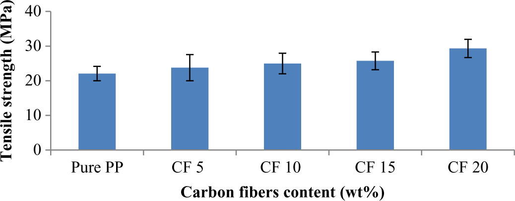
Tensile strength levels of PP/CF composites containing 0, 5, 10, 15, or 20 wt% CFs. CFs: carbon fibers; PP: polypropylene.
Figure 2 shows the influence of the number of melt-blending cycles on flexural strength. The viscosity of the PP decreased when the PP matrix melted, contributing to a better fluidity, which led to a more mixture of PP and CFs. When a force was exerted on the composites, this force could be dispersed evenly to the CFs in the PP matrix. As a result, when composites contained 20 wt% CFs, the flexural strength increased by 8–10 MPa.
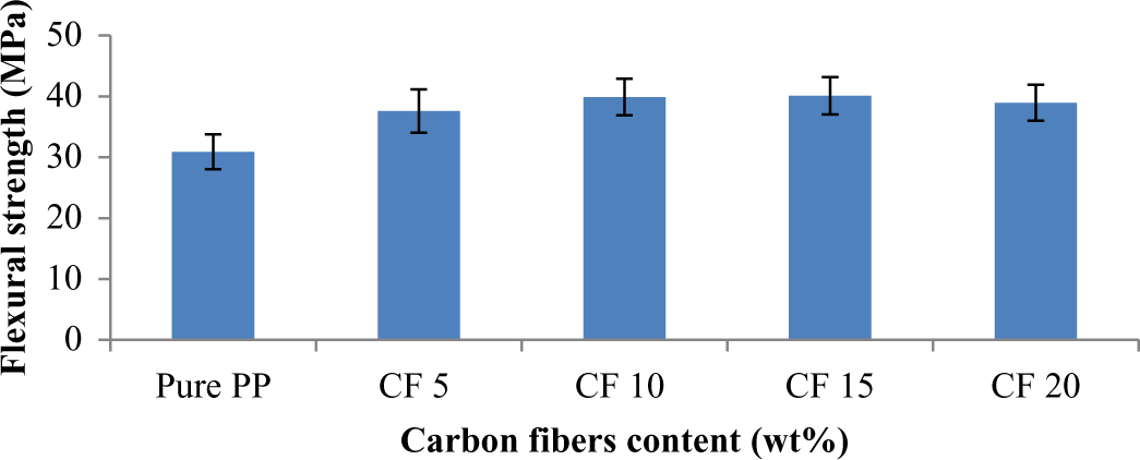
Flexural strength levels of PP/CF composites containing 0, 5, 10, 15, or 20 wt% CFs. CFs: carbon fibers; PP: polypropylene.
Figure 3 illustrates that with an increase in CF content, starting from 5 wt% up to 10, 15, and eventually 20 wt%, the impact strength of the composites decreased by 71, 73, 83, and 82%, respectively. This was because when CFs were added to the PP matrix, their great orientation led to a concentration of stress. The CFs could not bear lateral impact, which decreased the impact strength of the resulting composites. Table 1 summarizes the variation in tensile, flexural, and impact strengths in percentage.
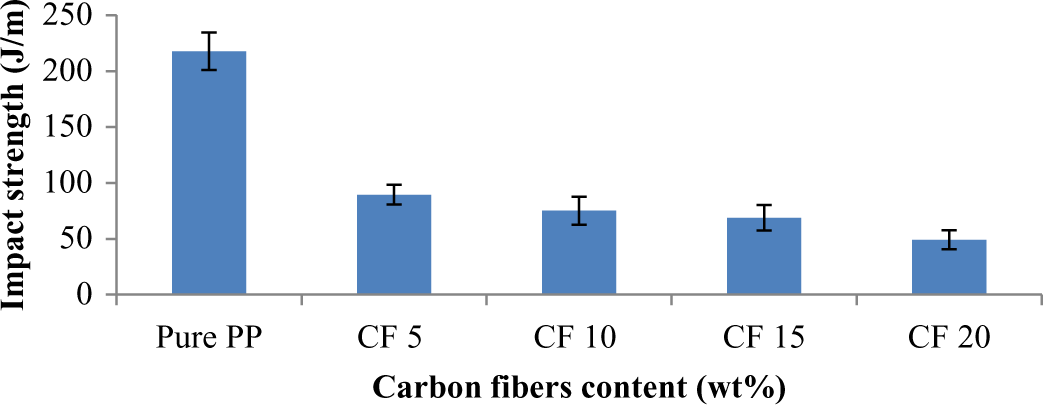
Impact strength levels of PP/CF composites containing 0, 5, 10, 15, or 20 wt% CFs. CFs: carbon fibers; PP: polypropylene.
Variations in tensile, flexural, and impact strengths in percentage (%).
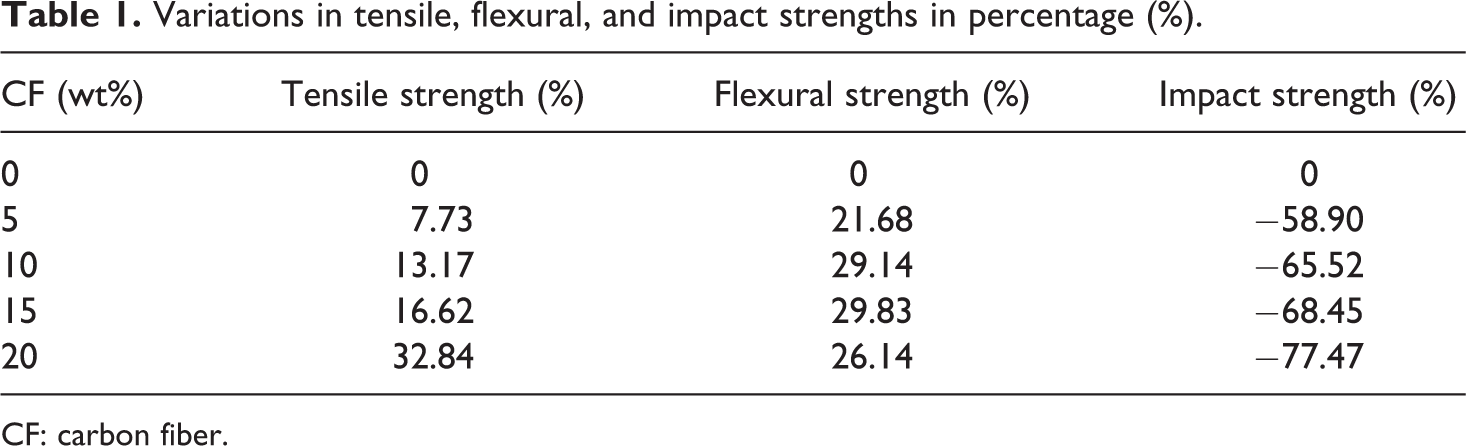
CF: carbon fiber.
Figure 4 shows that the injection process does not deliver all starting CFs to the end product. Some of the CFs are stuck in the injection machine and called as “residual fiber content”, which is found in previous studies. 12,13 In particular, when the CF content was 15 and 20 wt%, the residual fiber content was 9.57 and 9.44%, respectively, making the electrical and mechanical properties of these two PP/CF composites similar.
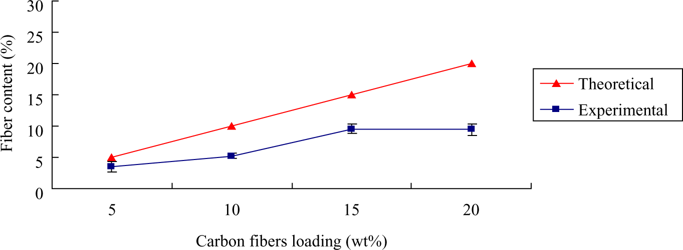
Fiber content of PP/CF composites containing 5, 10, 15, or 20 wt% CFs. Samples are melt blended six times and then thermally treated at 800°C in a muffle to determine the residual fiber content. CFs: carbon fibers; PP: polypropylene.
The CFs had a length of 6.2 mm. Figure 5 illustrates that the CFs that had been melt blended one time have a length of 1 mm, which is a result of damage by stress from shearing during the melt-blending process.
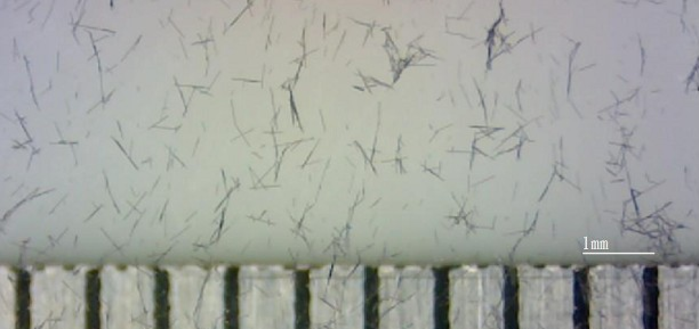
Carbon fibers in the PP/CF composites (15 wt% carbon fibers) after thermal treatment. CF: carbon fiber; PP: polypropylene.
Surface resistivity of inorganic composites
Surface resistivity of PP/CF composites
Figure 6 shows that a pure PP plank is insulating and exhibits great surface resistivity, which is above 10 12 Ω/square. When the CF content was 5 wt%, the surface resistivity of the PP/CF composites slightly decreased. This decrease was due to the chemical structure of carbonized CFs, which was composed of hexagonal carbon atoms that were able to transmit electrons. When the CF content was increased to 10 wt%, the surface resistivity distinctly declined to 2 × 10⁵ Ω/square. This decrease was ascribed to the electrical conduction network constructed by the CFs in the composites, which facilitated electrons transmission. This observed result was called a percolation phenomenon, and similar phenomena have been reported in many previous studies. The greater the amount of CFs, the lower the surface resistivity. In particular, with 20 wt% CF, the PP/CF composites exhibited the lowest surface resistivity.
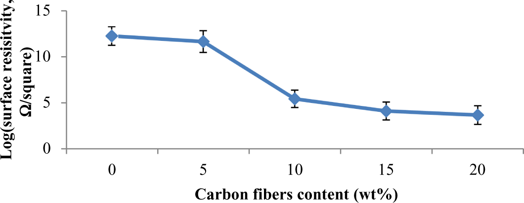
Surface resistivity of PP/CF composites containing 0, 5, 10, 15, or 20 wt% CFs. CFs: carbon fibers; PP: polypropylene.
Surface resistivity of PP/CF/GF composites
Figure 7 shows the surface resistivity levels of PP/CF/GF composites. With 15 wt% CFs, the composites had a surface resistivity of 3.3 × 10³ Ω/square. Surface resistivity increased with an increase in GF content. After the melt-blending process, carbon and GFs were evenly distributed in the PP matrix. The CFs formed an electrical conduction network in the PP matrix, making the resulting PP/CF/GF composite conductive. However, an increase in GF, which was a nonconductor, gradually damaged the electrical conduction network, resulting in an increasing surface resistivity of the composites.
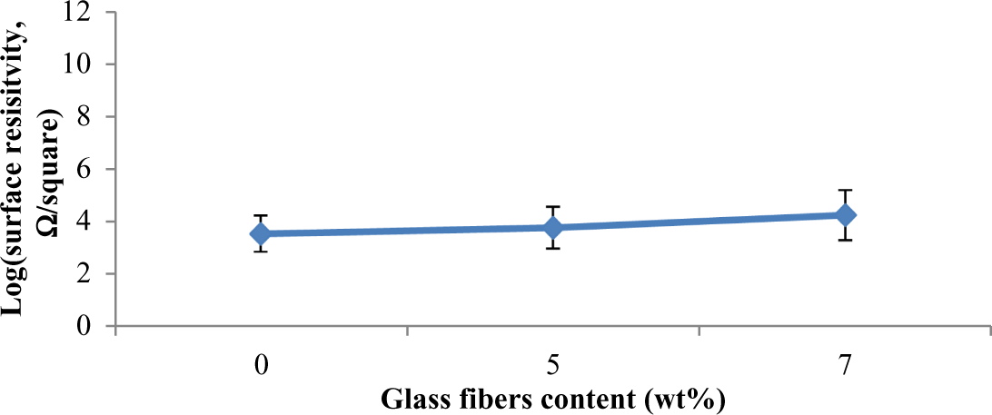
Surface resistivity of PP/CF/GF composites containing 15 wt% CFs and 0, 5, or 7 wt% GFs. CFs: carbon fibers; GF: glass fibers; PP: polypropylene.
EMSE of inorganic composites
EMSE of PP/CF composites
Figure 8 shows the EMSE levels of PP/CF composites containing 5, 10, 15, or 20 wt% CFs in the frequency range of 300 kHz to 3 GHz. Pure PP planks were insulating; therefore, they hardly exhibited any EMSE regardless of the frequency. At 144 MHz, for a plank with 5 wt% of CF, the EMSE was −6.44 dB. For a comparable plank with 20 wt% of CF, the EMSE was −33.32 dB. This indicates that CFs increase the EMSE level of a composite. Surface resistivity measurements showed that the lower the surface resistivity was, the higher the EMSE was. At frequencies of 900, 1800, and 2450 MHz, the EMSE levels of composites that contained 5 and 20 wt% were −1.25, −6.57 and −6.91 dB, and −22.83, −22.83, and −26 dB, respectively. When the CFs were 15 wt%, the composite’s EMSE was optimal, yielding an EMSE of above −20 dB and a shielding ratio of above 99.9%.
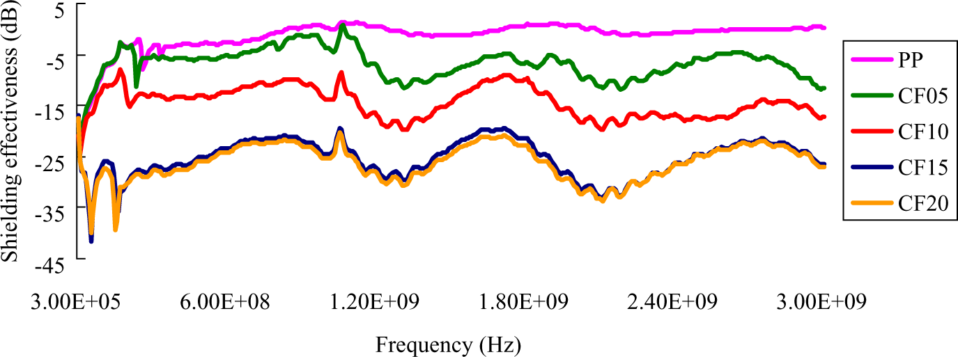
EMSE of PP/CF composites containing 0, 5, 10, 15, and 20 wt% CFs. EMSE: electromagnetic shielding effectiveness; CFs: carbon fibers; PP: polypropylene.
EMSE of PP/CF/GF composites
Figure 9 shows that the more GFs the planks had, the less the EMSE. The GFs were not conductive and the presence of glass prevented the CFs from providing EMSE. The addition of GFs reinforced the composite’s mechanical properties but decreased the composite electrical properties.
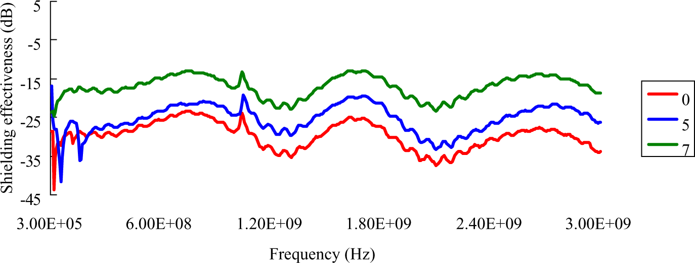
EMSE of PP/CF/GF composites containing 15 wt% CFs and 0, 5 or 7 wt% GFs. EMSE: electromagnetic shielding effectiveness; CFs: carbon fibers; GF: glass fibers; PP: polypropylene.
Conclusion
With 0 wt% CF and 0 wt% GF, a plank had a tensile strength of 22.06 MPa, a flexural strength of 30.86 MPa, and an impact strength of 217.67 MPa. A similar plank with 20 wt% CF and 0 wt% GF had strengths of 29.31, 38.98, and 49.04 MPa, respectively; this plank has excellent EMSE but low impact strength. Percolation phenomena decreased surface resistivity and promoted EMSE, and the presence of GFs inhibited EMSE. However, the EMSE of the PP/CF/GF composites was still satisfactory, reaching above 15 dB when the composites were composed of 15 wt% CFs and 5 or 7 wt% GFs. Both the PP/CF and PP/CF/GF composites were able to shield static electricity and electromagnetic waves, and the novelty of this study is that the mechanical properties of the resulting composites remain to a certain degree regardless of the 16 blending cycles. The proposed technique provides a practical manufacturing method that reduces polymer waste pollution by recycling and reclaiming the waste as well as promotes functionality and eco-friendliness of the resulting composites.
Footnotes
Funding
This research received no specific grant from any funding agency in the public, commercial, or not-for-profit sectors.