
Abstract
Sandwich structures have been studied extensively for planar structures; however, the use of composite tubing, manufactured by pultrusion, in a bending situation where a core material can contribute to take shear stresses, can find many applications in modern structures made of composite materials. The objective of this article is to develop analytical solutions for axial effective modulus and major Poisson’s ratio of a pultruded unidirectional composite tubing filled with a core material. In this work, the unidirectional composite tubing and its core are considered to have transversely isotropic and isotropic properties, respectively. For the validation of the results, the obtained exact analytical solutions are reduced to a case where both the materials are isotropic and compared to the existing solutions for an isotropic material filling in an isotropic tube. Further validations of our exact analytical solutions for the transversely isotropic tubing and isotropic core are carried out employing a finite element analysis of the same structure, where the results show excellent agreements between the analytical solutions and the numerical results. Finally, a parametric study is conducted to investigate the variations in the effective properties of the two-phase composite cylinder based on the variations in the skin and/or core geometries and their material properties.
Keywords
Introduction
Composite sandwich structures, as one of the commonly used composite systems and structures, have been among the best candidates for use in specific structural applications (such as bending) where ultralightweight and high-performance materials are needed. Typically, these composite structures comprise strong face sheets (e.g. thin sheets of metals, plastics, ceramics, and composite thin laminates) that are cocured to a very lightweight core material (e.g. low-to-high density foam as well as honeycomb structures). Sandwich structures provide an efficient method to increase the flexural rigidity without a significant increase in the structural weight. 1 Thus, structures, based upon a minimum face sheet thickness adequate to carry the in-plane loads, can be made to carry out-of-plane loads and to be stable under compression without a significant weight penalty. 2 Upon application specifications, composite sandwich structures have been used with different structural designs and geometries among which planar and tubular composite sandwich structures are the most commonly used geometries. Aerospace structures, in particular, modern launch vehicles, helicopter blades, optical benches for space applications, and nonferrous ship hulls are among some of the current applications. 1 –5 With increasing use of fiber-reinforced composite sandwich structures with different geometries for various applications, it has become necessary to investigate the mechanical behavior of such structures when they are subjected to external loads. Sarzynski and Ochoa 3 studied flexure responses of the composite sandwich beams with carbon-epoxy laminate face sheets and carbon foam core subjected to bending loads. In addition, failure modes of the composite sandwich beam structures are investigated by Daniel et al., 4 where the initiations of various failure modes depending on the material properties of the structural constituents (i.e. the face sheets and core materials), geometric dimensions, and the type of loading were observed. In their study, 4 the composite sandwich beams were made of unidirectional carbon/epoxy face sheets and aluminum honeycomb as well as polyvinylchloride closed cell foam cores.
The tubular sandwich composite structures can be effectively fabricated by means of pultrusion processing technology, where pultrusion is one of the fastest and most cost effective composites manufacturing methods. 6 Pultrusion is well suited to produce multilayer cylindrical composite structures, in particular, tubular sandwich structures, prestressing tendons, and reinforcing bars, because it can provide structures with a high degree of axial reinforcement. The basic operation of pultrusion is simple in concept but quite complex in detail because of the number of mechanical, chemical, and physical factors that are simultaneously involved in the process. 4 –8 A schematic of the pultrusion setup is shown in Figure 1.
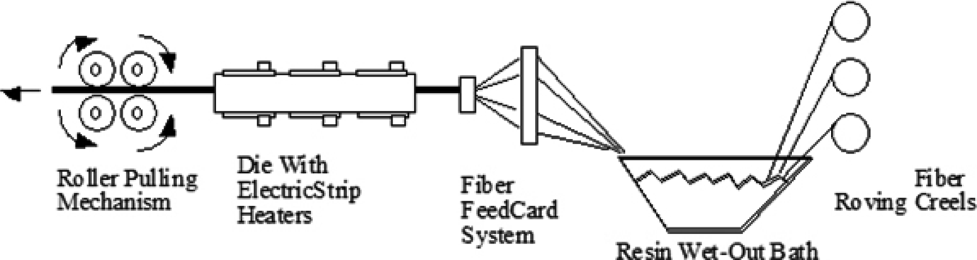
Schematic representation of the pultrusion setup. 9
By embedding fiber optic sensors in the composite part during pultrusion process, Kalamkarov et al. 9 have investigated the development of residual stresses in the composite part inside the pultrusion die. Kalamkarov et al. 10 , 11 developed smart pultruded fiber-reinforced polymer reinforcements with embedded Bragg grating and Fabry-Perot fiber optic sensors, where the pultruded smart reinforcements were evaluated and applied for structural strain monitoring and damage detection.
Many micromechanical models are available to predict the macroscopic behavior of fiber-reinforced composite materials, 12 , 13 where the fiber and the matrix materials were assumed to have isotropic properties. Basically, in these works, a representative geometric model of composite material is used to predict the effective properties of fiber-reinforced composite materials. One of the most used models is the composite cylindrical model introduced by Hashin and Rosen. 12 To obtain transverse shear properties of a fiber composite system, Christensen 13 used a model that is very closely related to the composite cylinder model. This model assumes that the fiber, the matrix, and the interface are continuous materials and the constitutive relations for the bulk composite materials are formulated based on the assumptions of continuum mechanics. Effective characteristics of unidirectional fiber composites and composite shells and plates with rapidly varying thickness were derived by Kalamkarov 14 by means of application of the asymptotic homogenization techniques. In particular, the explicit analytical formulae for effective properties of the composite sandwich shells with honeycomb fillers and different types of rib- and wafer-reinforced shells and plates have been derived. 14 These analytical results have been applied for the design and optimization of the composite and reinforced shells and plates. 15 Most recently, these results have been generalized in the case of generally orthotropic smart (in particular, piezoelectric) honeycomb sandwich shells and smart wafer-reinforced composite shells and plates. 16 , 17
Special classes of orthotropic materials are those that have the same properties in one plane and different properties in the direction normal to this plane. Such materials are called transversely isotropic, and they are described by five independent elastic constants (i.e. C11, C12, C22, C23, and C66), instead of nine for fully orthotropic.
The objective of the present article is to develop analytical formulae for effective axial Young’s modulus and major Poisson’s ratio for a unidirectional pultruded composite tube filled with core material to give a tubular sandwich composite structure. Here, we consider the material of composite tube as transversely isotropic (with isotropy in the plane normal to the tube axis, i.e. 2–3 planes) and core material as isotopic. We have assumed that the bonding between the composite tube and the tubular core is perfect with no property variations and no discontinuity at the interface.
Analytical modeling of a two-phase tubular sandwich composite structure
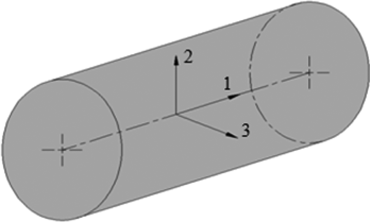
In this work, a two-phase cylinder model is considered (see Figure 2). We assume that the inside core (i) is an isotropic and the outside tube (o) is a transversely isotropic material.
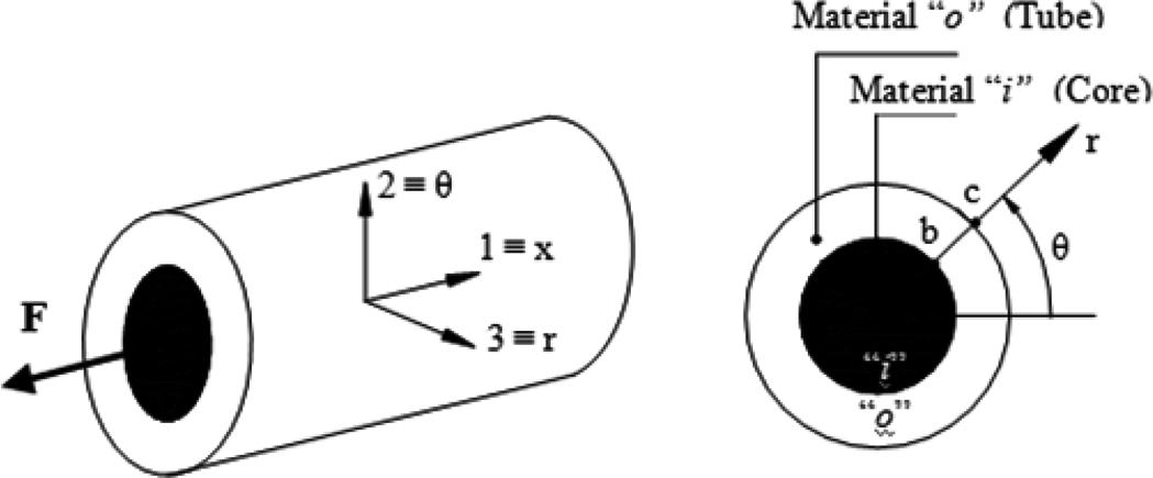
Two-phase composite cylindrical model.
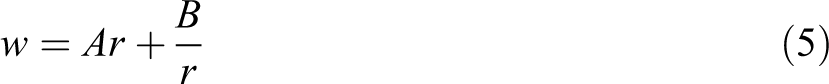
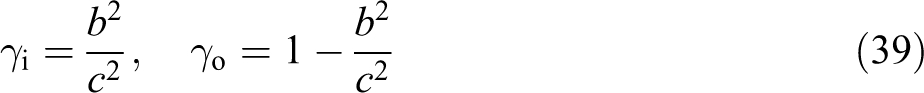
The outside radii of the core and the tube are denoted by b and c, respectively (see Figure 2). The problem of interest is axisymmetric with no dependence on polar angle θ. In addition, it is assumed that the inside core is perfectly bounded to the outside tube and an isostrain deformation takes place when cylinders are pulled in the x-direction (Figure 2). It means that the axial deformations are independent of radial coordinates at a given axial location. Therefore, the only equilibrium equation to be satisfied in this case is given as follows:
18

Note that for this problem, all other equilibrium equations are automatically satisfied.
Determination of transversely isotropic effective Young’s modulus
In general, the stress components in the cylindrical coordinate system can be formulated as
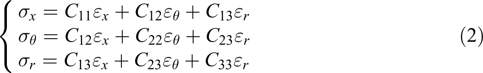
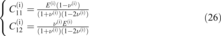
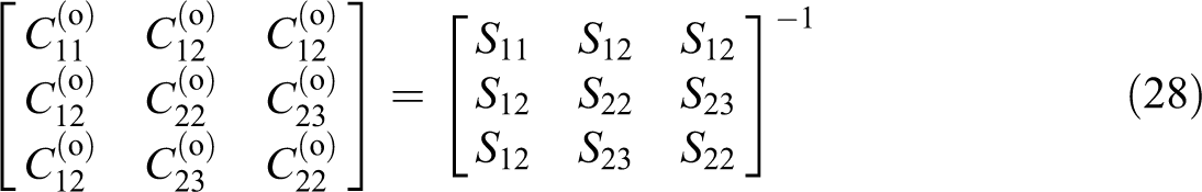
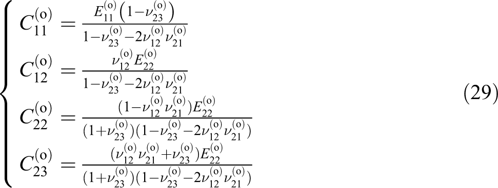
where σx , σθ , and σr are normal stresses, and εx , εθ , and εr are normal strains. Then, the constitutive equations for the isotropic inside filler (i.e. material i) and the transversely isotropic outside tube (i.e. material o) can be written using superscripts (i) and (o) for σ, ε, and C terms in equation (2).
The strain–displacement relationships in the cylindrical coordinate system for this particular problem can be reduced to the following relations
19

where the radial displacement is given by
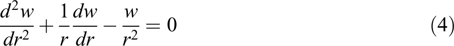
This is an Euler–Cauchy differential equation (a linear second order ordinary homogeneous differential equation), which has the following exact solution
20
Therefore, the radial displacements in the outside tube and the inside core can be written as follows


In the problem under study, strain


Since at the interface

\Three constants Ai
, Ao
, and Bo
entering equations (6) and (10) can be determined from the interface and outside boundary conditions. Substituting equations (6) and (10) into the strain–displacement equation (3), we obtain

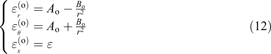
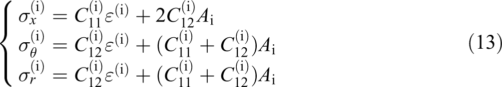
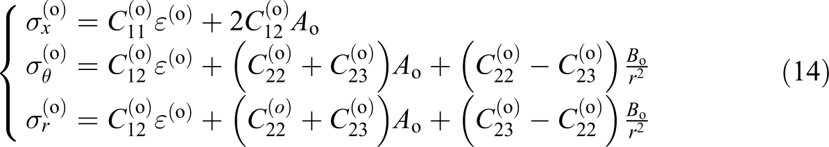
Substituting the strain components from equations (11) and (12) into constitutive equations for inner core (i) and outside tube (o) in equation (2) and after some mathematical manipulations, we obtain
The interface conditions at r = b are


The boundary condition at r = c is free and can be written as the following

The condition given in equation (15b) has already been satisfied (i.e.

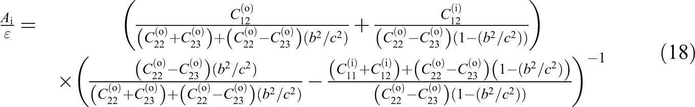
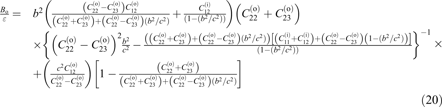
By substituting the stresses from equations (13) and (14) into conditions (15c) and (16), a system of two equations that can be used along with equation (17) to obtain the three unknown constants A
o, B
o, and A
i (considering

The applied axial load F (see Figure 2) and the effective axial Young’s modulus,
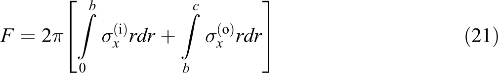
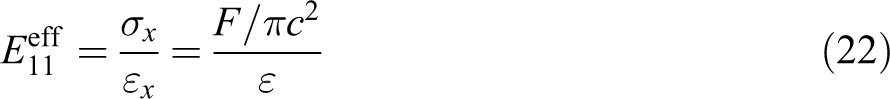
Substituting stresses

In order to obtain the final expression for

Equation (23) can be written in the following form

where parameters
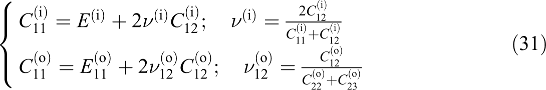
For the transversely isotropic outside tube, we can write

Coefficients
where
Substituting formulae for
Also, note that
21

and
From equations (23), (25), (26), and (31), we obtain the following expressions for
where
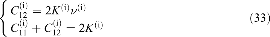
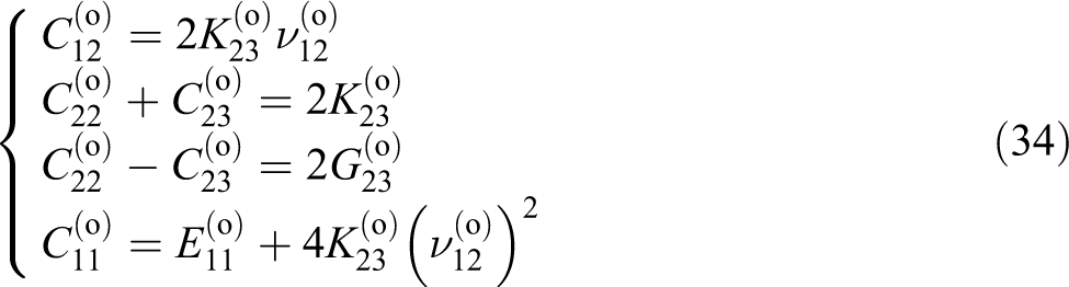
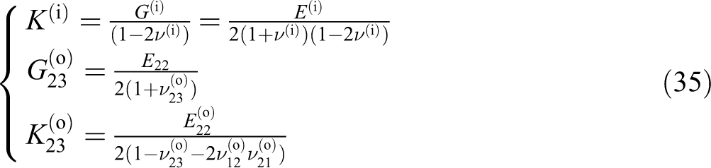
where the definition of the new parameters in the above equations (in terms of engineering material properties, E and ν; plain strain bulk modulus, K; and shear modulus, G) are as follows
Substituting equations (33) and (34) into equations (18) and (19), we obtain the following expressions for
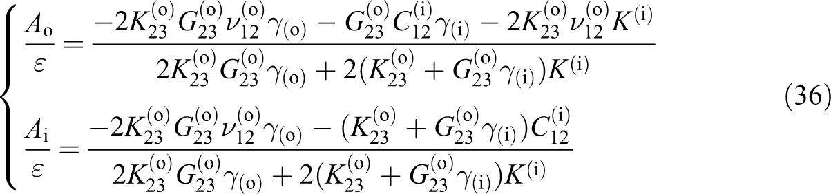
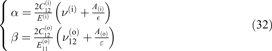
Next, using equations (32) and (36), we obtain the following explicit formulae for α and β
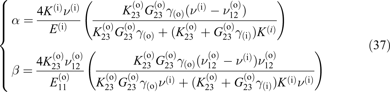
Substituting the expressions for
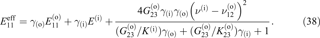
which is the exact analytical solution for the effective axial Young’s modulus of a tubular sandwich composite structure for the case of transversely isotropic outside tubular skin and isotropic inside core.
Reduction in
from transversely isotropic to fully isotropic case
We will use the following notation
where
where G is the shear modulus,

Substituting the parameters given by equation (40) into equation (38), we obtain the effective Young’s modulus for the isotropic case as
equation (42) coincides with a known formula that will be discussed later in this work.
Determination of effective major Poisson’s ratio
From the above formulated problem, we can also determine the effective major Poisson’s ratio
Note that
Effective composite cylinder model of radius “c”.
Using the relationships given by equations (6), (17), and (43), and coordinates shown in Figure 3, we can obtain
which is the exact analytical solution for the effective major Poisson’s ratio of a tubular sandwich composite structure, where the outside tube material is transversely isotropic in the plane normal to the tube axis and the inside core material is isotropic.
Reduction in
from transversely isotropic to fully isotropic case
Consider equation (45) in the limiting simplest case when both the inside core and outside tube materials are isotropic. Formula (45) after applying the isotropic relationships given by equation (40) reduces to the following form

Verification of the analytical solutions
The following formulae are known in the case when both the inside core material and the outside tube material are isotropic 13

where m, f, and μ stand for the outside matrix, inside fiber, and shear modulus, respectively. The similarities between equations (42) and (47) as well as between equations (46) and (48) validate the correctness of the above derived much more general formulae for the effective axial properties in the case of a transversely isotropic outside composite tube having an isotropic core material inside.
Finite element analysis of the tubular sandwich composite structure
Finite element method (FEM) is employed to model and analyze the performance of the tubular sandwich composite structure. The goal is to compare the results obtained analytically (in the previous sections) with those obtained numerically (in this section) to verify the accuracy of the analytical method. ANSYS 22 finite element software has been used to perform the load–displacement, strain, and stress analyses of the tubular sandwich composite structure under study. A three-dimensional model (i.e. one eighth of the full model due to the symmetry, shown in Figure 4) of a unidirectional composite tube filled with polycarbonate (or high density foam) is generated and solved for the displacements, strains, and stresses. The following dimensions have been used for the geometry of the composite tube
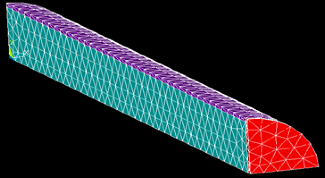
Three-dimensional solid model of one eighth of the sandwich composite tube with an end plate glued to the loading end (front end in red). Symmetric boundary conditions are applied to the cut surfaces (left, bottom, and rear end in gray) and uniform axial loading (normal to the front end in red) are applied to the tubular sandwich composite structure.

where ‘L’, ‘b’, and ‘c’ are the length, inner radius, and outer radius of a carbon/poly(ether–ether–ketone) (PEEK) unidirectional composite tube, respectively (see Figure 2). SOLID45 element, as a suitable candidate for orthotropic materials, was chosen from ANSYS finite element analysis (FEA) element library, and appropriated isotropic and transversely isotropic material properties were assigned to the inner core material and outer composite tube, respectively. To simulate the gripping condition of the loading side of the tube, a thin stiff plate (as a rigid element) was modeled and glued to the loading end of the tube, where the surface load is to be applied (as shown in Figure 4).
Isotropic and transversely isotropic material properties, that is, modulus and Poisson’s ratios, were used for the inner core material (“i”, two different types: polycarbonate
23
and dense polyurethane foam
24
), outside unidirectional composite tube (carbon/PEEK, “o”,
25
), and the thin end plate, “p”; their values are given as follows
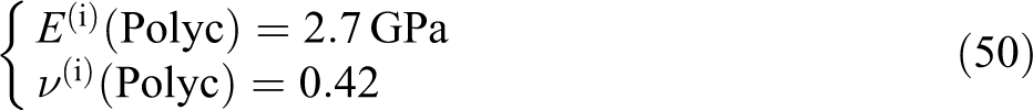
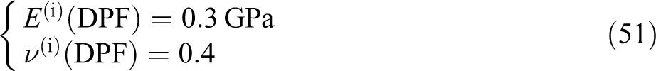
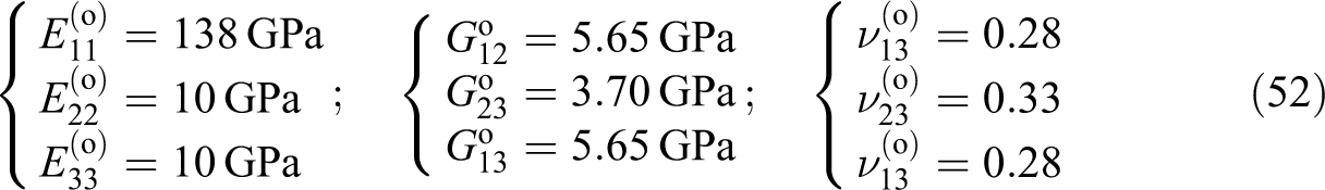
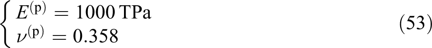
In the above equations, the terms E, G, and ν are modulus of elasticity, shear modulus, and Poisson’s ratio, respectively. The superscripts ‘i’, ‘o’, and ‘p’ represent the inner core, outer tube, and thin plate, respectively. In equations (50) and (51), the terms (DPF) and (Polyc) refers to polycarbonate and dense polyurethane foam, respectively, and the subscripts 1, 2, and 3 in equation (52) stand for axial, circumferential, and radial directions, respectively. Next, the created volumes (i.e. the inner core, outer tube, and thin plate) in the FEA were meshed by considering a proper mesh element size and type. It should be noted that due to the symmetry of the problem, only one eighth of the structure is modeled. Symmetric boundary conditions were applied at one end (i.e. rear end in gray) as well as the cut sides of the structure (i.e. left and bottom sides in gray) with fixed corner nodes. A uniform surface load was applied to the other end (i.e. front end in red) that was glued to the stiff end plate (see Figure 4).
Finally, the generated finite element model was solved for different cases (considering two different core materials, that is, polycarbonate and DPF), and the results obtained were to be used for the calculation of the effective axial constitutive properties of the sandwich composite tube. Mesh convergence studies (with a convergence criterion of less than 1% on displacement) were performed by increasing the number of the finite elements (i.e. decreasing the mesh size). Figure 5 shows the plots of the axial, circumferential, and radial displacement contours of the polycarbonate core sandwich composite structure subjected to an axial uniform load of 1000 N, respectively. These figures show that the axial displacements are uniform at any cross section of the tube along its longitudinal direction, as one would expect. Also, the radial displacements, away from the tube ends, are uniform. The circumferential displacements are zero or near zero, consistent with the assumption made in the analytical solution. It should be mentioned that as an alternative FEM approach, the end rigid plate was removed and the model was solved with all nodes at the loading side coupled to move together in the axial direction. These alternative approaches, away from the end loading points, produced similar results that will be discussed later in this work.
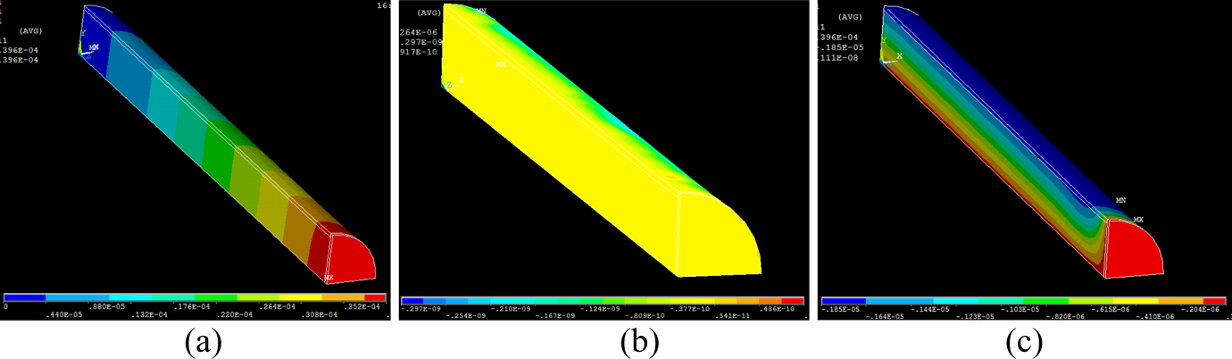
The contour plots of axial, circumferential, and radial displacements of the polycarbonate core sandwich composite tube under axial loading.
The displacement results (for both types of the core material) were further used to calculate the effective axial and radial strains, ε
11 and ε
33, of the sandwich composite tube. The effective axial Young’s modulus,
Calculations of
and
from FEA
The maximum axial displacement, at the loading end, and radial displacement, at the surface, from the FEA as well as the dimensions of the sandwich composite tube from equation (49) were substituted into equation (54) to find the values of the axial and radial strains, ε
11 and ε
33, respectively. Next, the averaged axial stress, σ
11, is obtained from equation (55). Finally, the strain and stress values were used in equation (56) to calculate the effective axial Young’s modulus,
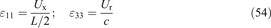


Here, Ux is the maximum axial displacement, Ur is the radial displacement, and A is the total cross-sectional area of the sandwich composite tube.
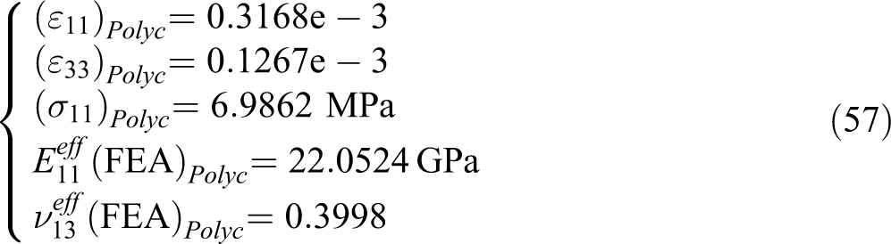
The following are the numerical values obtained from these calculations for the case of polycarbonate core sandwich composite tube
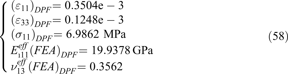
Similarly, the following results are obtained for the DPF core sandwich composite tube
The comparison of the FEA final results (i.e. the effective axial Young’s modulus,
Comparison of
and
values obtained from the analytical solutions and FEA
The exact analytical solutions for the effective axial Young’s modulus and effective major Poisson’s ratio of the sandwich composite tube for the transversely isotropic outer tube material and isotropic inner core material have been derived above and given in equations (38) and (45). It should be noted that the
To calculate the effective axial Young’s modulus and effective major Poisson’s ratio for the sandwich composite tube, first the dimensions and material properties given by equations (49) to (52) are used to calculate the parameters given in equations (35) and (39) (i.e.
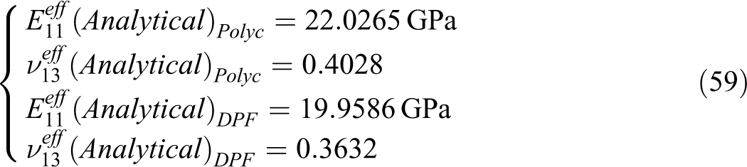
It can be seen that these values are very close to those obtained from the FEA given by equations (57) and (58). This comparison shows that both the techniques are accurate and predict similar effective properties for the sandwich composite tube with relative errors of less than 0.12% for the effective Young’s modulus and less than 1.9% for the major Poisson’s ratio as shown below
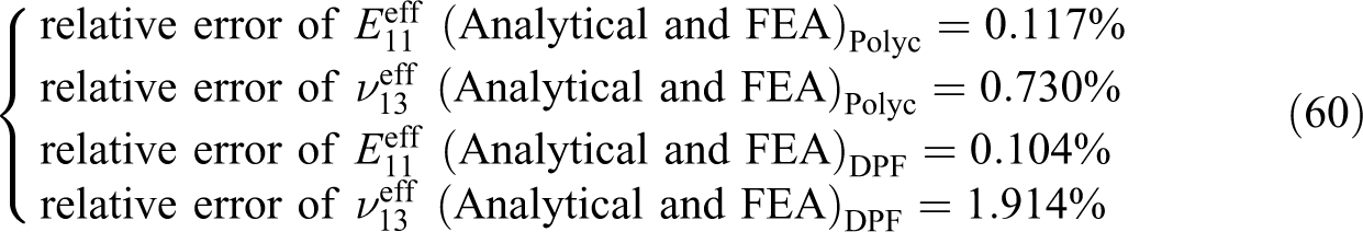
Therefore, an excellent agreement is achieved between the results obtained from the exact analytical solutions and the FEA introduced in this work. As mentioned earlier, a similar structure without the stiff end plate, but instead with coupled nodes at the loading end of the composite cylinder, was also modeled and solved in ANSYS FEA and produced similar results. The calculated effective longitudinal Young’s modulus,
Parametric study of the analytical solutions for the transversely isotropic tubular sandwich composite tube
The exact analytical solutions for
Effect of the volume content of the core material on (a) the effective longitudinal Young’s modulus and (b) the major Poisson’s ratio of the sandwich composite tube.
Similarly, Figure 6(b) gives the effect of the volume fraction of the core, γ
i, on the effective major Poisson’s ratio,
These graphs demonstrate that the analytical solutions derived in this work can be employed for design purposes of similar two-phase composite cylindrical structures. It is now readily possible to determine the required volume percentage of the transversely isotropic constituent materials to obtain a two-phase composite cylindrical structure with desired mechanical properties. It should be noted that these formulae are applicable to any similar structures with material anisotropy levels up to transversely isotropic for the outside tube and isotropic for the inside core and is a valuable tool for design purposes of composite tubular structures.
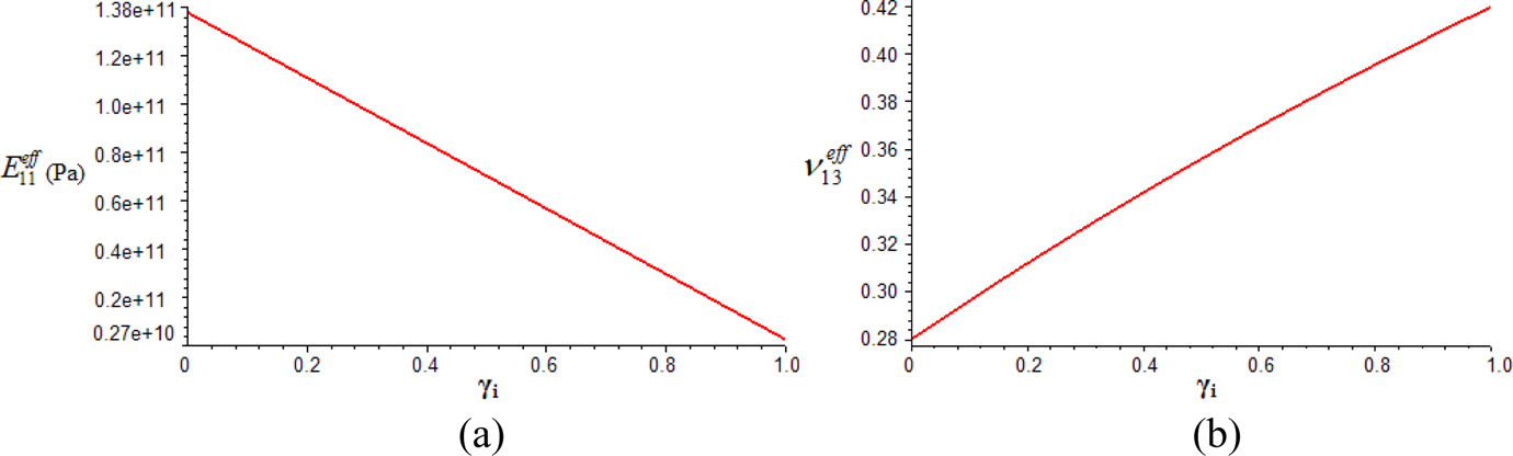
To investigate the influence of the outside material properties on the effective properties of the two-phase composite cylinder, parametric studies based on the variations in the material properties of the outside tube are carried out and discussed. For this purpose, all five independent transversely isotropic mechanical properties of the outside composite tube (i.e.
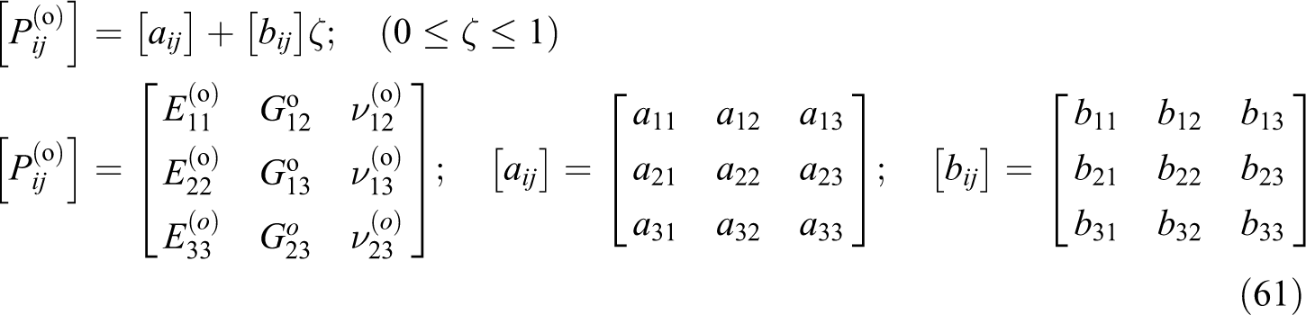
In equation (61),
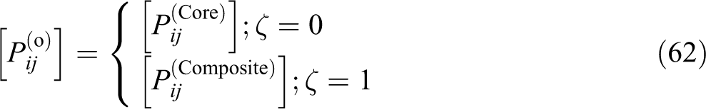
Note that
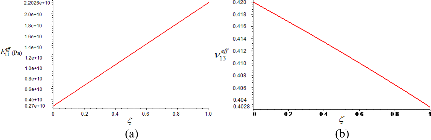
Variations in (a) the effective longitudinal Young’s modulus and (b) the major Poisson’s ratio of the sandwich composite tube versus the variation in the composite tube properties.
Both of these graphs demonstrate linear behavior. As one would expect, both graphs show that the effective properties of the sandwich composite tube are identical to the individual properties of the polycarbonate core, when properties of the core material is assigned to the outer composite tube, and identical to the effective properties of the sandwich composite tube, when the carbon/PEEK properties are assigned to the outer composite tube. The results presented in this section (i.e. Figures 6 and 7) can also be used for proper geometry and materials selection for the design of composite cylindrical structures with desired effective properties.
Conclusions
The exact analytical formulae for transversely isotropic effective longitudinal Young’s modulus and effective major Poisson’s ratio of tubular sandwich composite structure are derived and introduced here. In this work, a two-phase cylinder model is considered with a transversely isotropic outer composite tube material and an isotropic inner cylindrical core. These analytical solutions can be used to obtain the effective axial properties of any such tubes and fillers with known material properties. For the validation purposes, an FEA is performed to numerically investigate the responses of the sandwich composite tube under an axial loading where the displacement results are used to find the values of the effective axial Young’s modulus and effective major Poisson’s ratio. Next, the material properties of the individual inside core and outside composite tube, used in the FEA of the sandwich composite tube, are substituted into the exact analytical solutions to compute the effective material properties
Footnotes
Authors’ Note
The authors A.L.K. and D.A. have equally contributed to this work.
Funding
The Office of Naval Research (ONR) financially supported the ADPICAS project under the government grant numbers N00014-00-1-0692, N00014-05-1-0586, and N00014-07-1-0889; also the Natural Sciences and Engineering Research Council of Canada (NSERC) has supported A.L.K.