
Abstract
In this article, the analysis of the behavior of cracked pipeline repaired with bonded composite wrap subjected to traction effect is performed using three-dimensional finite element methods. The stress intensity factor at the crack front was used as the fracture criteria. The stress intensities at the internal and external positions of repaired crack were compared. The effects of the mechanical and geometrical properties of the adhesive layer and the composite wrap on the variation of the stress intensity factor at the crack front were analyzed. The obtained results show that the presence of the bonded composite repair reduces significantly the stress intensity factor, which can improve the life span of the pipe.
Introduction
Over the past two decades, the composite repaired pipelines have proven its efficiency. It has been shown that it can perform adequately under different environments and industrial projects. 1 Most of the pipeline companies use composite materials for repair and reinforcement programs, but the challenges that confronts the industry is determined when the composite materials can be used and which systems are best suited for repairing a given damaged mechanism for a long time as possible.
In the design of a composite repair system for offshore pipes, combined loads, fatigue loads, impact and a galvanic corrosion form the basis for additional consideration. Factors such as wave motion and contact with other structures, such as ships and other risers, are realistic sources for impact damage. Every year in the United States alone the between 2 and 3.3 billion dollars are spent repair and replace the corroded gas and petroleum pipelines.
The original use of composite materials was for repairing galvanic corrosion caused due to electrochemical coupling of carbon fibers with steel alloys, which is another mechanism where design of interfaces, treatment technology and environmental conditions are carefully characterized. 1 –5
The effect of cyclic pressure loads on the performance of a composite repair system is quite important in tailoring its stiffness and strengths especially for hoop and off-axis fiber reinforcements. The size and shape of the defect region can have a significant effect on the level of repair that can be achieved. In addition, composite materials have successfully been used to repair dents, wrinkle bends, induction bends and pipe fittings including elbows and tees as well as repair of offshore risers. 6
Numerous studies have been performed that address the damage initiation and propagation during fatigue of composite laminates, leading to the observation of a gradual decrease in the static strength (and modulus of elasticity) as it is subjected to an increasing number of cycles at a given stress level. 7
Alexander and Francini 8 presented the history of onshore pipeline repairs using composite materials. Even though the long-term performance of composites incorporating physical and chemical degradation is of great importance in pipeline applications, yet the data reflecting relevant environmental conditions are still sparse. Toutanji and Dempsey 9 worked on establishing fiber-reinforced polymer composites as an effective mean for the repair and rehabilitation of pipelines. They developed a theoretical model with stress expressions and circumferential stress curves. This study focused on the application of fiber-reinforced polymer on steel pipes.
In this study, we evaluated the crack repair with composite patch of circumferential through cracks in pipelines subjected to the traction effect using finite element analysis. The effects of different parameters on the repair performance were highlighted.
Geometrical and finite element models
This study presents a three-dimensional finite element analyses by the code Abaqus for semicircular complete cracks in pipes repaired with Glass/epoxy patch. The pipe is subjected to a traction effect of amplitude p = 100 MPa (Figure 1). Figure 2 presents the geometrical model of the pipe and the cracks. The geometrical characteristics of the cracked pipe are:
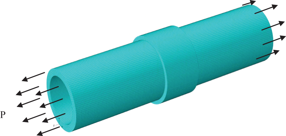
Repaired pipe under traction.
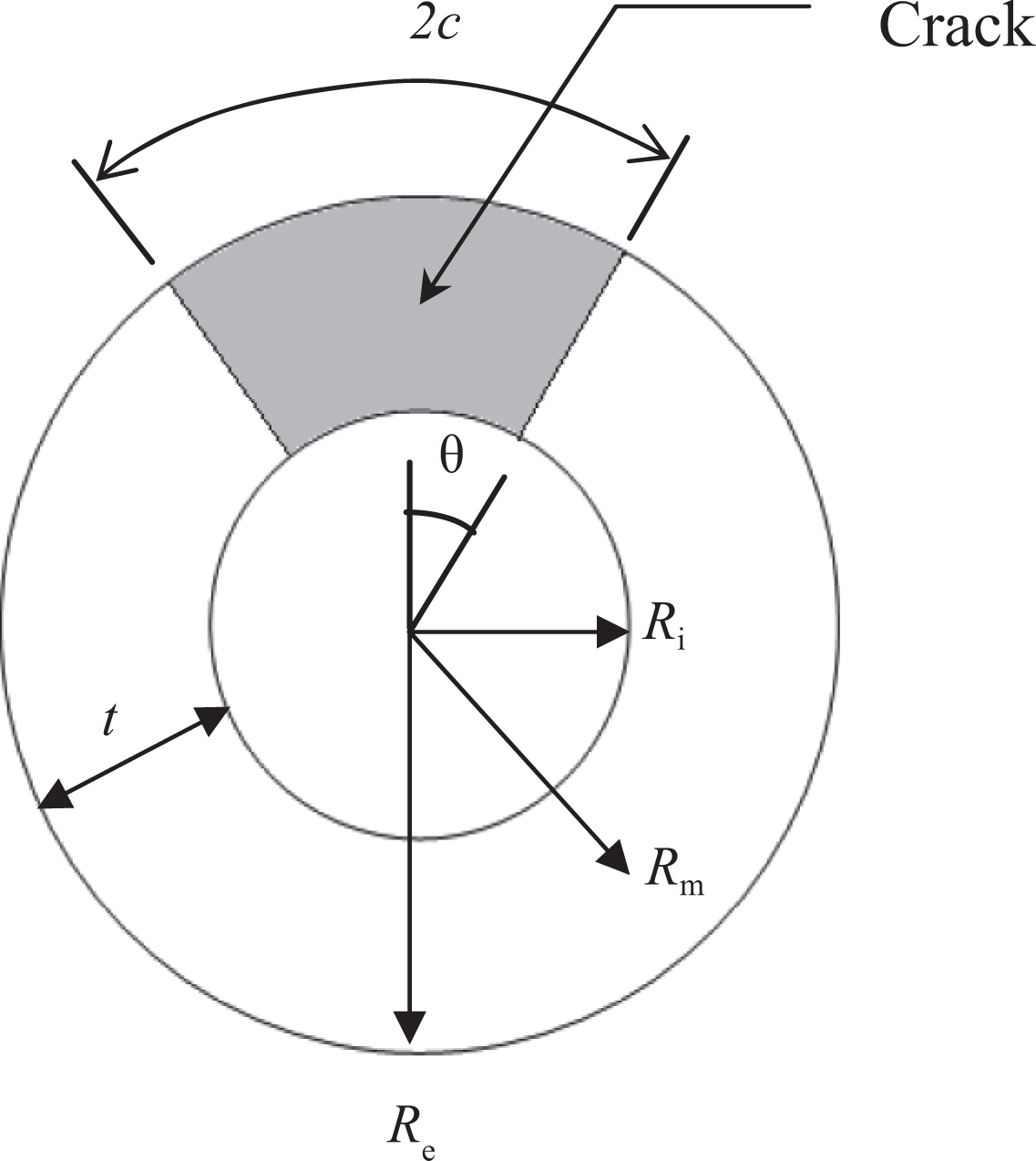
Geometrical model of the pipe and the crack.
external diameter, R 0 = 31 mm;
internal diameter, R i = 24 mm;
equivalent diameter, R m = 27.5 mm.
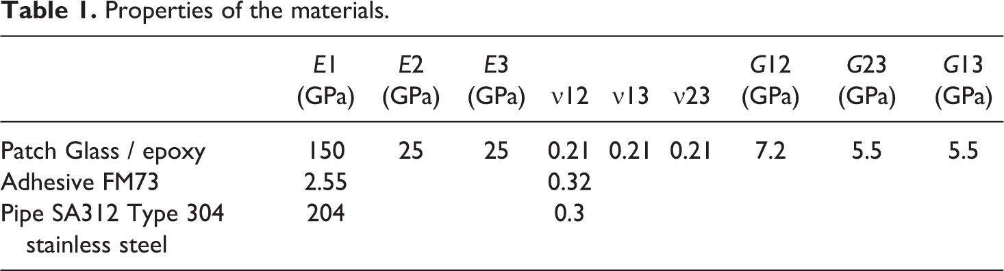
The size of the crack is represented with the angle θ. The pipe material is the SA312 Type 304 stainless steel. The patch repair is bonded to the pipe with the structural adhesive FM73. Table 1 gives the elastic properties of the pipe, the patch and the adhesive.
Properties of the materials.
The analysis involved a three-dimensional finite element method to supplement and analyze the experiments using a commercially available finite element code ABAQUS. 10
The finite element model consisted of three subsections, to model the cracked pipe, the adhesive and the composite patch. The plate had four layers of elements in the thickness direction, the adhesive had only one layer of elements through thickness and the patch had two layers of elements through thickness. To generate crack front, some brick elements are replaced by ‘crack block.’ These crack blocks are meshes of brick elements which are mapped into the original element space and merged with surrounding mesh. Boundary conditions and loads are transferred to the crack block elements. The mesh was refined near the crack tip area with an element dimension of 0.053 mm using at least 15 such fine elements in the front and back of the crack front. Figure 3 shows the overall mesh of the specimen, and Figure 4 presents the mesh refinement in the crack tip region. The stress intensity factor (SIF) at the crack front was extracted using the virtual crack closure technique (VCCT). The VCCT criterion uses the principles of linear elastic fracture mechanics (LEFM) and, therefore, is appropriate for problems in which brittle crack propagation occurs along predefined surfaces. VCCT is based on the assumption that the strain energy released when a crack is extended by a certain amount is the same as the energy required to close the crack by the same amount. 10 For example, Figure 5 illustrates the similarity between crack extension from i to j and crack closure at j.
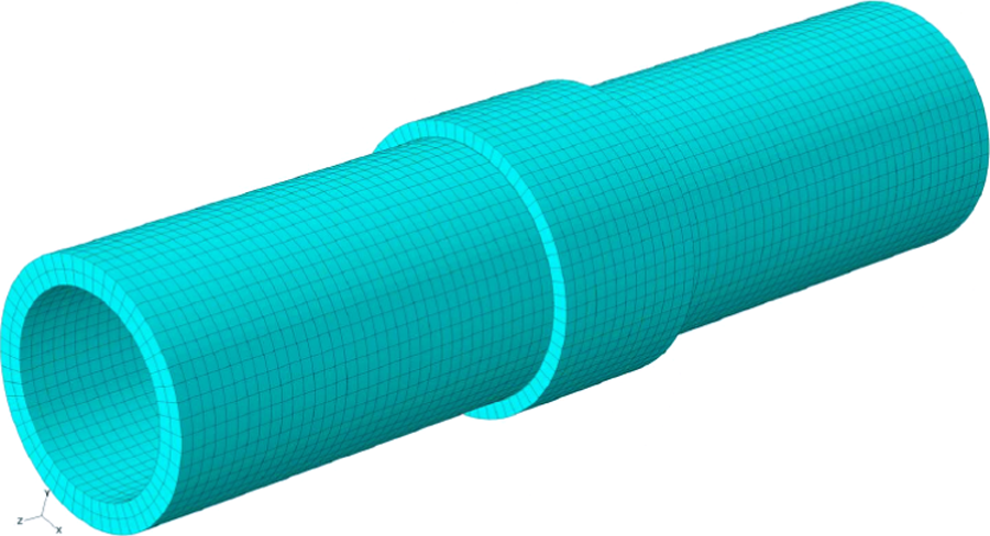
Typical mesh model of the global structure.
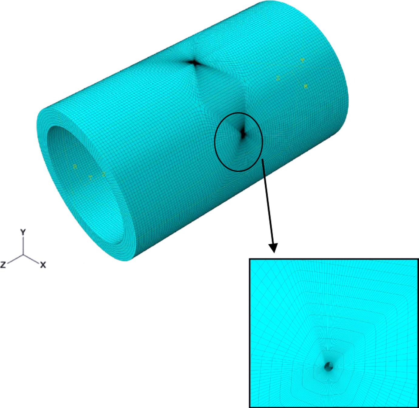
Mesh model at the crack front.
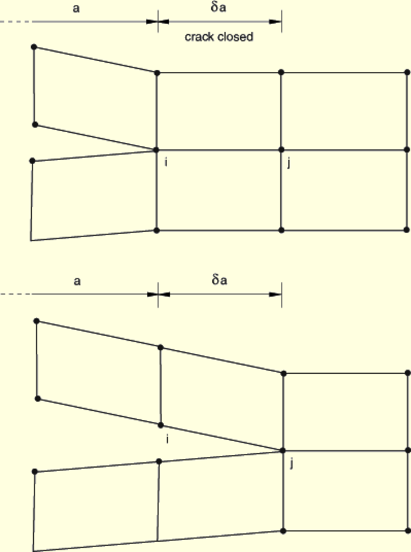
Mode I: the energy released when a crack is extended by a certain amount is the same as the energy required to close the crack.
The SIFs K
I, K
II and K
III are, respectively, the modes I, II and III crack propagation, usually used in LEFM to characterize the local crack tip/crack line stress and displacement fields. They are related to the energy release rate (the J-integral) through


Abaqus/Standard provides an interaction integral method to compute the SIFs directly for a crack under mixed-mode loading. This capability is available for linear isotropic and anisotropic materials. 10
Results and discussions
Comparison between repaired and unrepaired crack for internal and external positions
SIF calculations were conducted for repaired and unrepaired cracks in pipe under traction in order to estimate the repair performances. Figure 6 presents the variation in the SIF for repaired and unrepaired cracks at external position of the crack front for different crack angles. One notes a major reduction in the SIF. For example, for an angle of crack of 45° the reduction rate of the SIF is about 59% and one notices an asymptotic behavior of the SIF variation for repaired crack at the external position which proves that the good efficiency of the repair by composite wrap for pipe under traction loading. It can also be noted, according to Figure 5, that for repaired crack, the SIF exhibits an asymptotic behavior as the crack length increases. This is due to the fact that there is a stress transfer between the repaired pipe and the composite wrap throughout the adhesive layer.
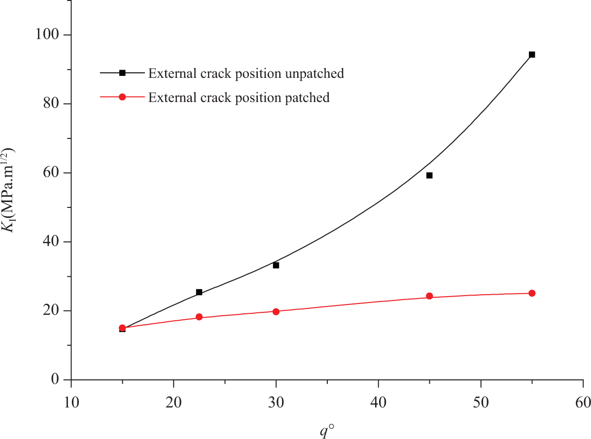
Stress intensity factor (SIF) vs. crack angle for external position crack patched and unpatched.
The variation in the SIF along the internal crack front (unpatched front) is analyzed in Figure 7. It is noticed that repair reduces even the concentration of the stresses for internal crack position. As an example, for an angle of crack of 45° the reduction ratio is about 54%.
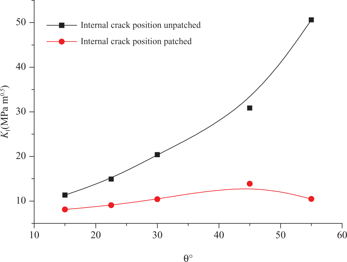
Stress intensity factor (SIF) vs. crack angle for internal position crack patched and unpatched.
Figure 8 presents a comparison of the variation in the SIF between cracks in internal and external positions of the pipes repaired with composite patch. It is noticed that the difference between the SIFs of the repaired cracks in internal and external position is considerable for all interval of variation in the crack angle θ. The relative difference is about 42% for a crack angle of 45°.
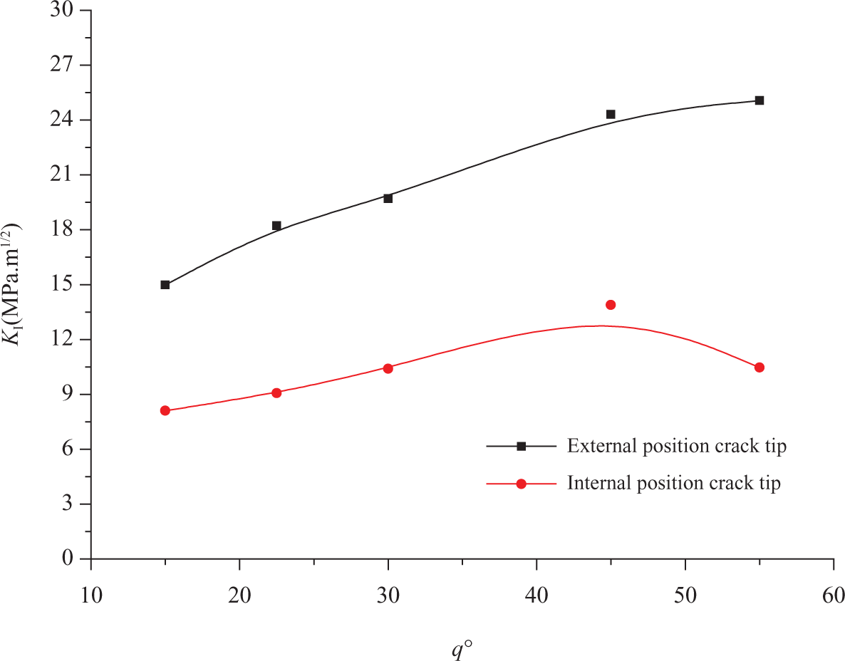
Stress intensity factor (SIF) vs. crack angle for internal and external position crack tip.
Figure 9 presents the distribution of the SIF along the crack front for repaired and unrepaired pipe with composite patch for a crack angle of 45°. It is observed that the reduction in the stress is considerable on two positions of cracks especially on the external position that have a direct contact with the repair patch. One concludes that the repair of a crack with a composite patch is efficient under the traction effect. Quantitatively, the SIF is reduced in the external position of the crack from 9.02 to 33.20 MPa (m)1/2 with a reduction ratio of 72%; and in the internal position of a crack from 19.7 to 26.7 MPa (m)1/2 with a reduction ratio of 26%.
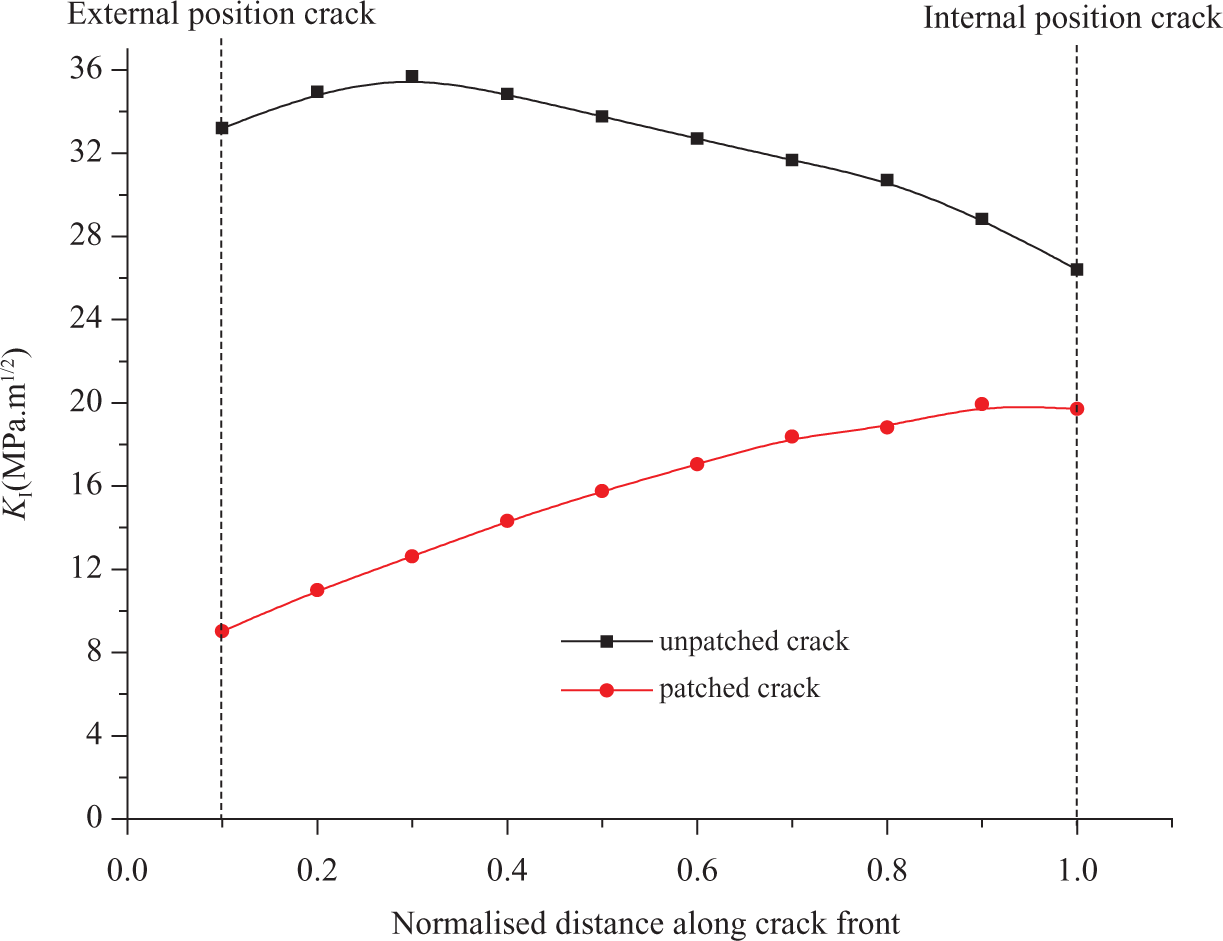
Distribution of the stress intensity factor (SIF) along crack front for patched and unpatched cracks.
Effect of the adhesive thickness
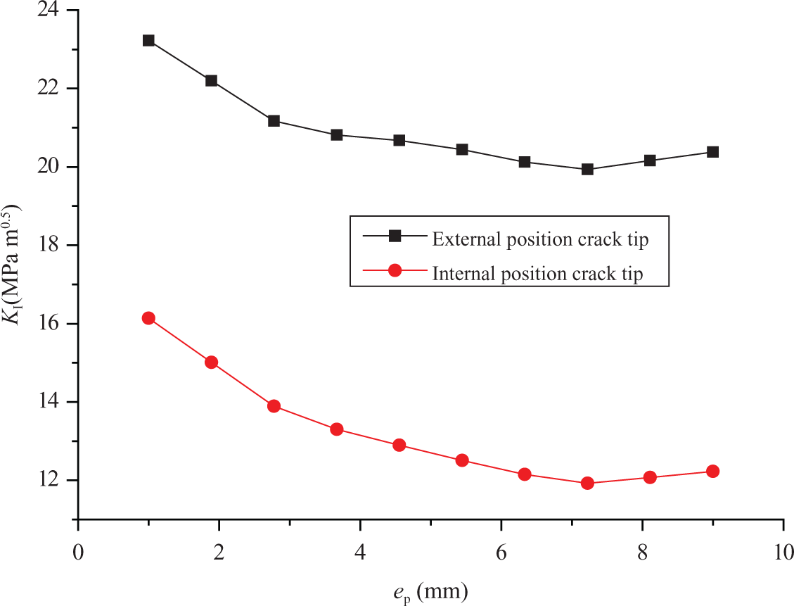
The adhesive layer is the bridge which allows the transfer of stress from the stress concentration region toward the composite patch. Figure 10 described the variation in SIF according to the thickness of the adhesive for internal and external positions of repaired cracks. It can be noted that the increase in the adhesive thickness leads to the growth of the SIF, especially for internal positions of cracks.
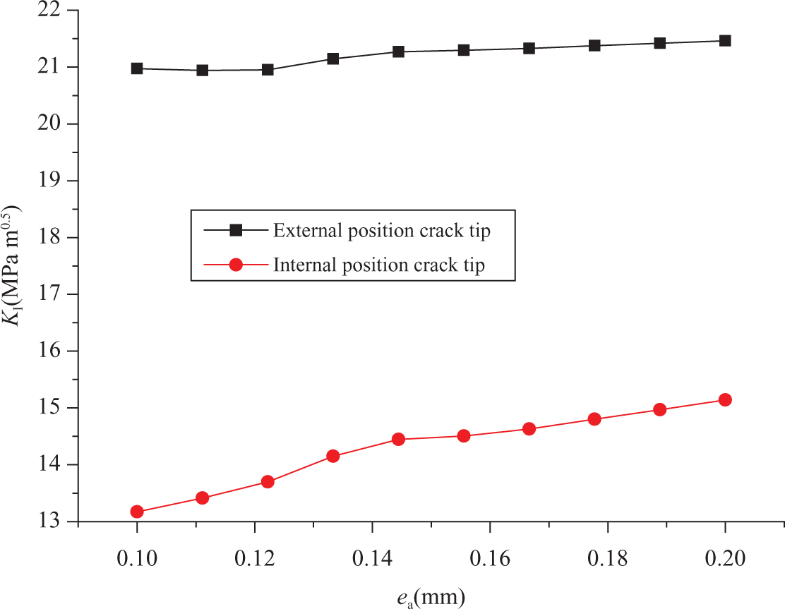
Stress intensity factor (SIF) vs. adhesive thickness.
To confirm the result, Figure 11 presents the distribution of the stresses along the crack front, with the variation in the thickness of the adhesive. It is noticed that the reduction thickness of the adhesive decreases the SIF. The low thickness of the adhesive is beneficial for composite repair patch.
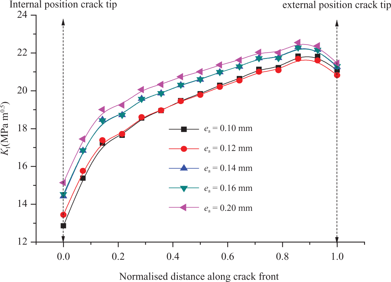
Distribution of the stress intensity factor (SIF) along the crack front for different adhesive thicknesses.
Effect of the mechanical properties of the adhesive
Figure 12 presents the variation in the SIF according to the Young modulus for cracks tips both in the internal and external positions. One remarks that the increase in the adhesive Young modulus decreases the stress concentrations, which are beneficial for the repair. For example, the reduction ratio of SIF between Ea = 1000 MPa and Ea = 3000 MPa in the cases of internal and external positions of cracks are, respectively, about 22% and 3%.
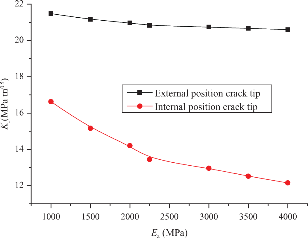
Stress intensity factor (SIF) vs. adhesive Young modulus.
Figure 13 shows the distribution of the SIF according to the various Young modulus along a front crack tip. One observes that the Young modulus of the adhesive is inversely proportional to the SIF. One concludes that a high Young modulus allows a good transfer of the stresses and generates the reduction in FIC.
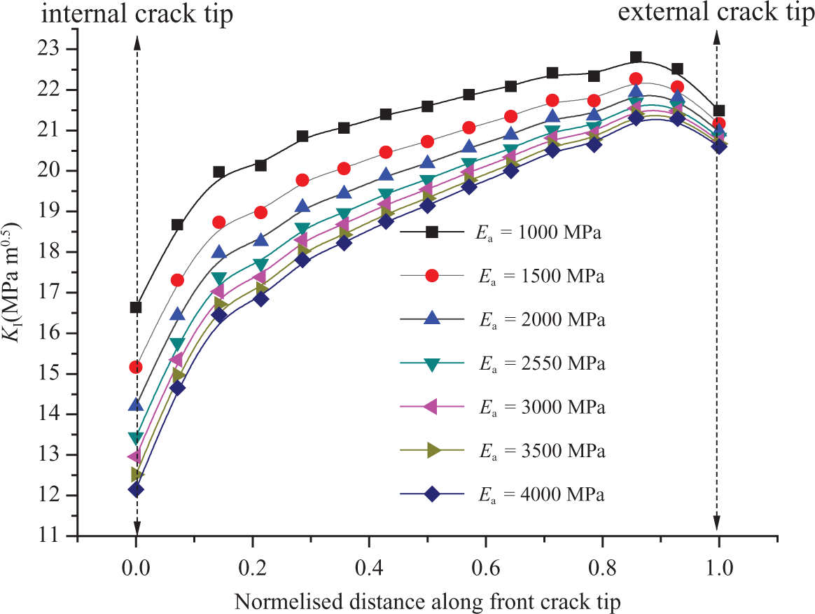
Distribution of the stress intensity factor (SIF) along the crack front for different Young modulus.
Effect of the patch thickness
Figure 14 presents the variation in the SIF according to the patch thickness for the internal and external positions of cracks. The increased thickness of the patch decreases the SIF which is beneficial for the repair of two positions of the crack. A thick patch allows good absorption of the stresses.
Stress intensity factor (SIF) vs. patch thickness at the external and internal crack tip.
Conclusion
This study demonstrates that the reduction in the stress intensity by the composite patch repair of cracked pipe subjected to the traction effect is significant, which can improve the lifespan of repaired pipes. The optimization of the mechanical properties of the adhesive and the composite patch can improve the repair and reinforcement performances and durability significantly. This optimization must equilibrate between the reduction in the stress intensity at the repaired defect and the reduction in the risk of adhesive layer failure.
Footnotes
Acknowledgment
The authors extend their appreciation to the Deanship of Scientific Research at King Saud University for funding the work through the research group No. RGP-VPP-035.
Funding
This work was supported by King Saud University.