
Abstract
In this study, solid particle erosion behaviour of glass fibre mat-based polyester laminate composite materials was investigated by varying the impact velocity and the impingement angle and sizes of the abrasive particles. Impact velocities used in the tests were 23, 34 and 53 m/s, while the impingement angles were 15°, 30°, 45°, 60°, 75° and 90°. Silicon dioxide particles with average diameters of 250, 500 and 1000 μm were used as abrasive particles. Experimental data were taken as reference and values of erosion rates were obtained as functions of impact velocity, impingement angle and the size of the abrasive particles. The results obtained exhibited typical ductile behaviour of glass fibre-reinforced composites, where the maximum erosion rate was recorded at an impingement angle of 30°, and the erosion rates decreased as the impingement angle increased. Moreover, the erosion rates increased with the increase in impact velocity and particle size. Finally, the worn out surfaces of the test specimens were investigated on two different devices, optical microscope and scanning electron microscope.
Introduction
Due to their excellent properties, composites are extensively used as structural materials in various components and engineering parts in automotive, aerospace, marine and energy applications. Composites in pipeline carrying sand slurries in petroleum refining, helicopter rotor blades, pump impeller blades, high-speed vehicles and aircraft operating in desert environments are often exposed to conditions in which they may be subjected to solid particle erosion. Their mechanical properties such as flexural strength can be degraded by the presence of localized impact damage after particle erosion. It is also widely recognized that composites have a poor erosion resistance against operational requirements of industrial environment. That may be overcome by understanding the characteristics of the composites. 1 –4
There has been an increasing trend, recently, towards researches on erosive wear; one of the types of surface damages where eroding particles of different dimensional sizes under various impact velocities and impingement angles is striking and affecting the top surfaces of materials, leading to material losses and functional variations. 5 –9
Many researchers, therefore, have investigated the erosion behaviour of composites worn out by solid particles. Patnaik et al. 10 carried out erosion test to study the effects of various operational and material parameters on erosive wear behaviour of polyester composites reinforced with three different weight fractions of woven E-glass fibre-reinforced composites in an interacting environment. The findings of the experiments indicate that erodent size, fibre loading, impingement angle and impact velocity are the significant factors in a declining sequence affecting the wear rate. Significance of erosion efficiency in identifying the wear mechanism is highlighted. Tewari et al. 11 studied solid particle erosion behaviour of unidirectional carbon fibre- and glass fibre-reinforced epoxy composites. They evaluated different impingement angles (15°–90°) at three different fibre orientations (0°, 45° and 90°). They found that unidirectional carbon fibre- and glass fibre-reinforced epoxy composites exhibit semi-ductile erosion behaviour, with a maximum rate of erosion at 60° impingement angle. They also found that the fibre orientations had a significant influence on erosion. Li and Hutchings 12 measured the rates of erosive wear for a series of eight polyester-based one-component castable polyurethane elastomers, with widely varying mechanical properties. Erosion tests were conducted with airborne silica sand, 120 μm in particle size, at an impact velocity of 50 m/s and impact angles of 30° and 90°. For these materials that showed similar values of rebound resilience, the erosion rate increased with increasing hardness, tensile modulus and tensile strength. Patnaik et al. 13 reviewed the research on solid particle erosion behaviour of fibre- and particulate-filled polymer composites. The new aspects in the experimental studies of erosion of fibre- and particulate-filled polymer composites were emphasized in this article. Implementation of experimental designs and statistical techniques in analyzing the erosion behaviour of composites was discussed. Recommendations were given on how to solve some open questions related to the structure–erosion resistance relationships for polymers and polymer-based hybrid composites. Arjula and Harsha 14 evaluated the erosion efficiency (η) of polymers and polymeric composites by collecting the available data from the literature pertaining to solid particle erosion under normal impact conditions. The objective of this article is to show the usefulness of the η parameter in identifying various mechanisms in solid particle erosion. The erosion efficiency map is plotted, which indicates the influence of hardness of various polymers and polymer composites on their erosion resistance. Tilly and Sage 15 investigated the influences of velocity, impact angle, particle size and weight of eroding particles on nylon, carbon fibre-reinforced nylon, epoxy resin, polypropylene and glass fibre-reinforced plastic material. Lindsley and Marder 16 found impact velocity (v) to be a critical test variable in erosion, and that it can easily overshadow changes in other variables, such as target material, impact angle, and so on. Goretta et al. 17 scrutinized solid-particle erosion of portland cement and portland-cement-based concrete and, for comparison, a nuclear waste glass. Using angular aluminium oxide (Al2O3) erodents of mean diameter ≈42, 63, 143 and 390 μm impacting the surface at 20° and 90° at 50 m/s, the researchers found the erosion rate to be a strong function of erodent size. Erosion rates of the three targets by rounded silicon dioxide (SiO2) sand erodent of mean diameter ≈450 μm were generally different from those of the ≈390 μm Al2O3 erodent. In a study conducted by Suresh et al., 18 solid particle erosion behaviour of polyetherketone (PEK) reinforced by short glass fibres with varying fibre content (0–30 wt%) was investigated. Here, the researchers evaluated different impact angles (15°–90°) and impact velocities (25–66 m/s) using silica sand particles as abrasives. PEK and its composites exhibited maximum erosion rate at 30° impact angle indicating ductile erosion behaviour. The erosion rates of PEK composites increased with increase in the amount of glass fibre. In the study by Harsha and Jha, 19 the researchers investigated erosion resistances of neat epoxy composites, unidirectional glass fibre-reinforced epoxy composites, unidirectional carbon fibre-reinforced epoxy composites and bidirectional E-glass woven-reinforced epoxy composites. Bidirectional glass fibre-reinforced epoxy composites exhibited higher erosion resistance than their unidirectional fibre-reinforced counterparts. This is connected to the fact that double directional composites absorb more impact energy. Roy et al. 20 characterized the solid particle erosion behaviour of four different types of polymer matrix composites reinforced with glass fibres. The erosion rates of these composites have been evaluated at two impact angles (90° and 30°) and two impact velocities (38 and 45 m/s). The erosion response, erosion efficiency and the erosion micromechanisms of these composites are presented and discussed in detail and also compared with the available data in the literature on similar materials. Rattan and Bijwe 21 conducted a research where they evaluated erosion wear behaviour of polyetherimide (PEI) and its composites using silica sand particles striking at a constant impact velocity but with varying angles of impingement. Although the mechanical properties of PEI improved substantially by carbon fabric reinforcement, they found that the erosion resistance of the material deteriorates by a factor of about four to six times at all angles of impingement. In spite of the fact that PEI is not a very ductile polymer (elongation to fracture, 60%), they found that it exhibits maximum wear at 15°, which is a characteristic of ductile and semi-ductile mode of failure.
In this study, erosion wear behaviour of glass fibre mat-based polyester laminate composite materials that have high strength, good electrical and thermal conductivities and are corrosion resistant, the features that make them suitable for long time use without the need for frequent maintenance services in areas such as cooling towers, ships, platforms and many other application fields, was investigated, wherein three different particle impact velocities, six different impingement angles and three different particle sizes were used in undertaking the tests.
Experimental study
Materials
The mat-reinforced composite materials used in this study were industrially produced at Pultech FRP, a Turkish Materials Company, where “hand lay-up” technique is used to fabricate the composites. Glass fibre mat-laminated sheet is produced by combining unsaturated polyester resin (Neoxil CE 92 N8) with glass fibre mat and inorganic fillers (alumina trihydrate, kaolin and calcium carbonate) and laminating under heat and pressure. The nominal thickness of the composite plates obtained in this process is 3.2 mm. These laminates have excellent mechanical, physical and electrical properties and include special grade flame resistance. These properties are shown in Table 1. DIN Hm 2471 quality grade was used in our glass fibre mat-laminated sheet composite materials. Material produced under this grade is self-extinguishing (Flame-retardant UL94–FVO), arc extinguishing and track resistant with very good electrical and mechanical properties. Preferentially, these materials are applied in high-voltage and electrical engineering fields as construction units.
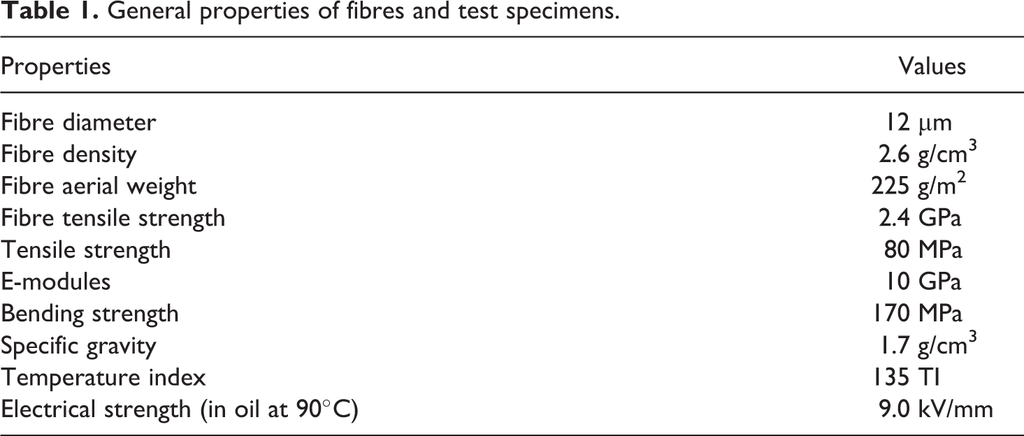
General properties of fibres and test specimens.
Erosion testing
Solid particle erosion testing device used in this study is given in Figure 1. The device basically consists of a sand hopper, flow control valves, manometers, particle tank, nozzle, specimen holder, pressure setting valve and eroded sand collector. Dry compressed air is mixed with the particles, which are fed at a constant rate from the sand hopper into the pressurized particle tank and then accelerated by a compressor, thereby forcing the mixture through a tungsten carbide converging nozzle of 6 mm diameter. These accelerated particles impact the specimen, which can be held at various angles with respect to the impacting particles using an adjustable sample holder.
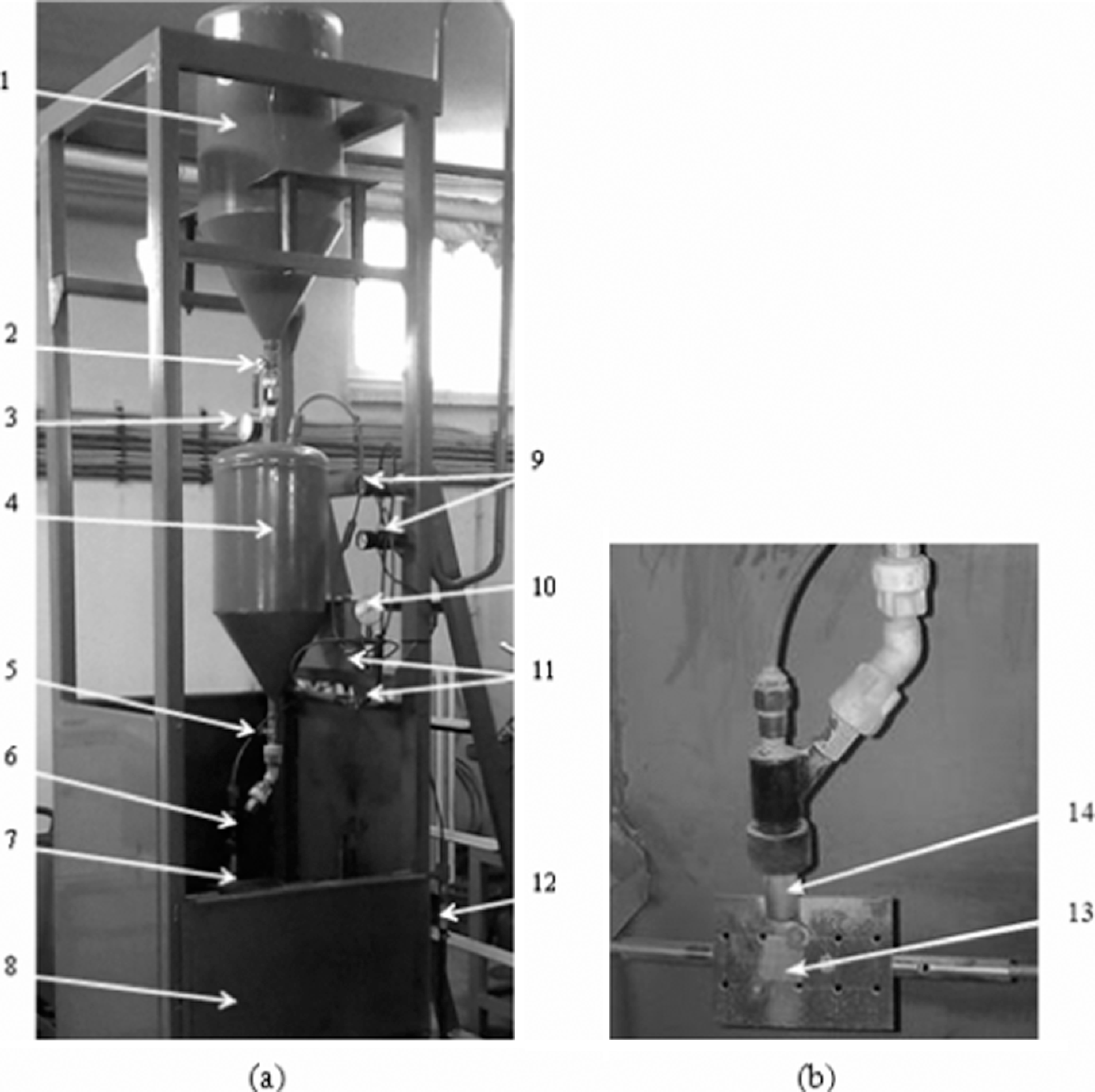
(a) Erosion test device: 1: sand hopper; 2,5: spherical valve; 3,10: manometer; 4: pressurized particle tank; 6: nozzle; 7: specimen holder; 8: eroded sand collector; 9: valve pressure setting; 11: flow control valves; 12: compressor insert manifold. (b) Details of test region: 13: specimen; 14: nozzle.
The impact velocity of the particles can be varied by varying the pressure of the compressed air. In order to determine the velocity of the eroding particles, many methods 22 –25 were used previously. In this study, the double disc method 26 was used to determine the velocity of the eroding particles, because this method is simple and economic. The particle velocities obtained by double disc method were 23, 34 and 53 m/s. For the erosion tests, a diamond-impregnated slitting saw was used to cut the samples into a size of 30 × 30 × 3.2 mm3 from the manufactured composite plate. All cut edges were finished using a fine silicon carbide paper. The standard test procedure was performed in accordance with ASTM G76-95 27 for each erosion test. The samples were weighed to an accuracy of 0.1 mg using an electronic balance. Then 10 kg of abrasive particles at a flow rate of 182.5 g/s were spurted on the specimen and then the latter was weighed again to determine its weight loss.
Optic microscopic views and chemical compositions of these particles are shown in Figure 2 and Table 2, respectively. The distance from specimen surface to nozzle end was 10 ± 1 mm as described in ASTM G76-95 standards.
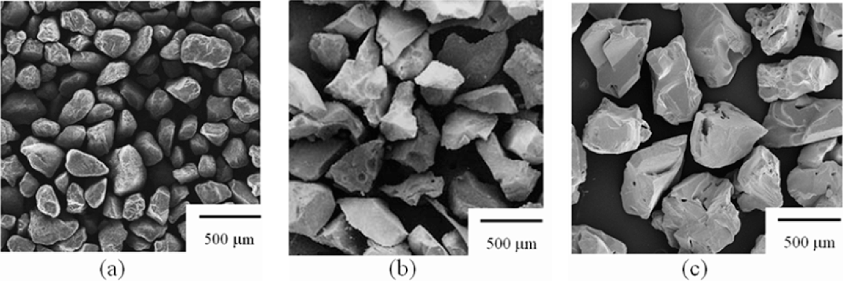
Optic microscopic views of SiO2 abrasive particles: (a) 250 μm, (b) 500 μm and (c) 1000 μm.
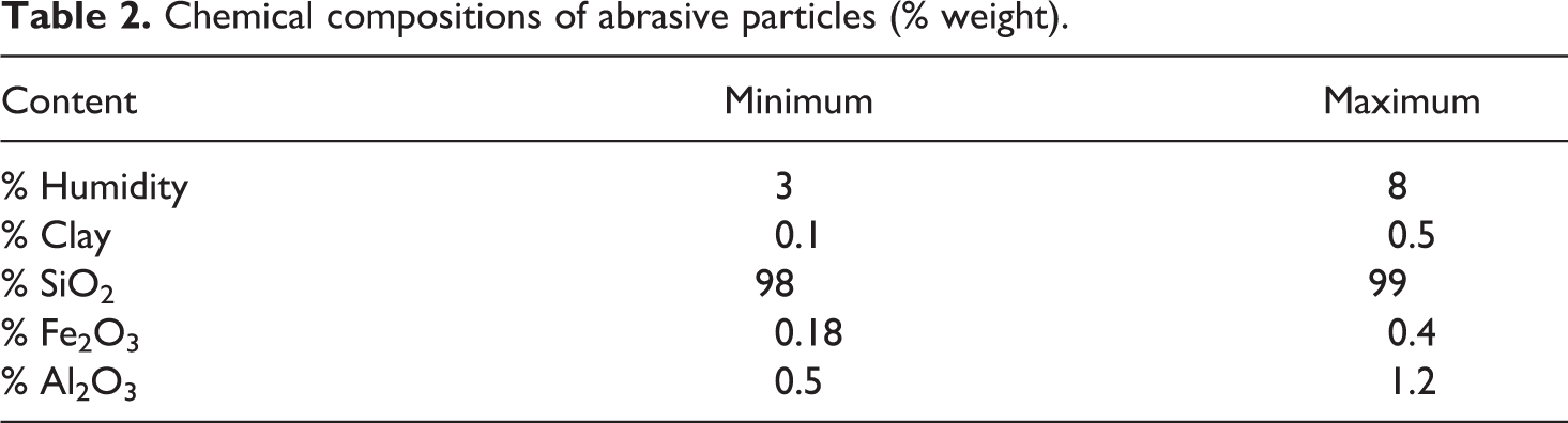
Chemical compositions of abrasive particles (% weight).
Results and discussion
Erosion rate
In this experimental study, glass fibre mat-based polyester laminate materials were subjected to erosive wear, where three different types of abrasive particles having sizes of 250, 500 and 1000 μm were used to strike the materials at velocities of 23, 34 and 53 m/s and impingement angles of 15°, 30°, 45°, 60°, 75° and 90°. The results obtained were used to plot the graphs in Figures 3 to 5. These graphs show variations in erosion rates of SiO2 abrasive particles of average diameters of 250, 500 and 1000 μm against impingement angles of the particles.
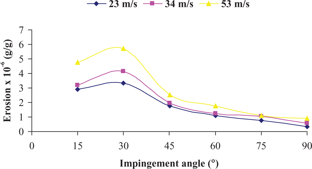
Variation in erosion rates with impingement angles for three different impact velocities of 250 μm SiO2 abrasive particles.
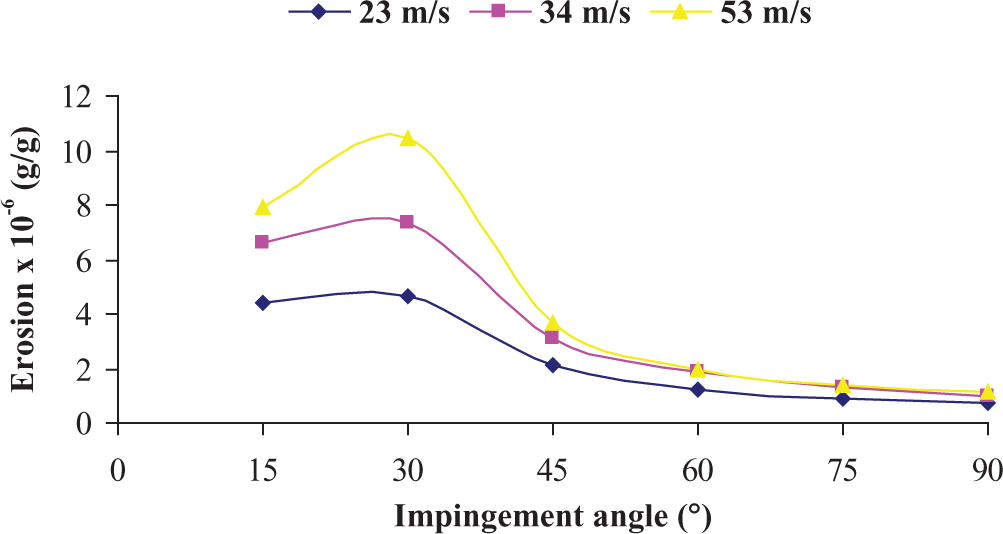
Variation in erosion rates with impingement angles for three different impact velocities of 500 μm SiO2 abrasive particles.
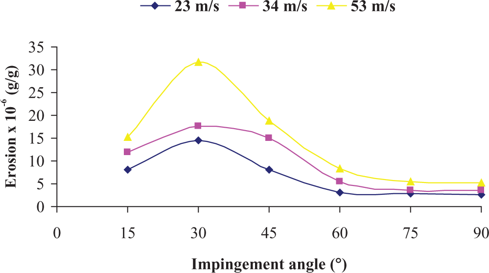
Variation in erosion rates with impingement angles for three different impact velocities of 1000 μm SiO2 abrasive particles.
The values of erosion rates (g/g) used to plot the graphs were determined by dividing the weight loss in the test specimens by the total weight of abrasive particles used in each test. In addition, every value in these graphs was obtained by taking an average value of three different tests performed around that value.
Comparison with literature
Studies made on erosive behaviour of composites, so far, have confirmed that wear rates generally depend on abrasive particles’ impingement angle, striking velocity and their sizes and that the wear rate is effectively affected by striking angle. 28,29 Maximum erosion rate for ductile materials generally occurs at 15°–30° impingement angles, while materials with brittle and semi-ductile behaviours exhibit maximum erosion rates at 90° and 45°–60°, respectively. 30,31
The tests conducted indicate that, at low and moderate particle speeds, the materials subjected to solid particle erosion experience surface damages prior to undergoing material losses. Then, as the particles persist keeping their contact with the surface, they cause deep indentations and grooves on the surface of the material. Figure 6 shows the graphs of variations of erosion with impact angle as obtained by combining studies from related literature.
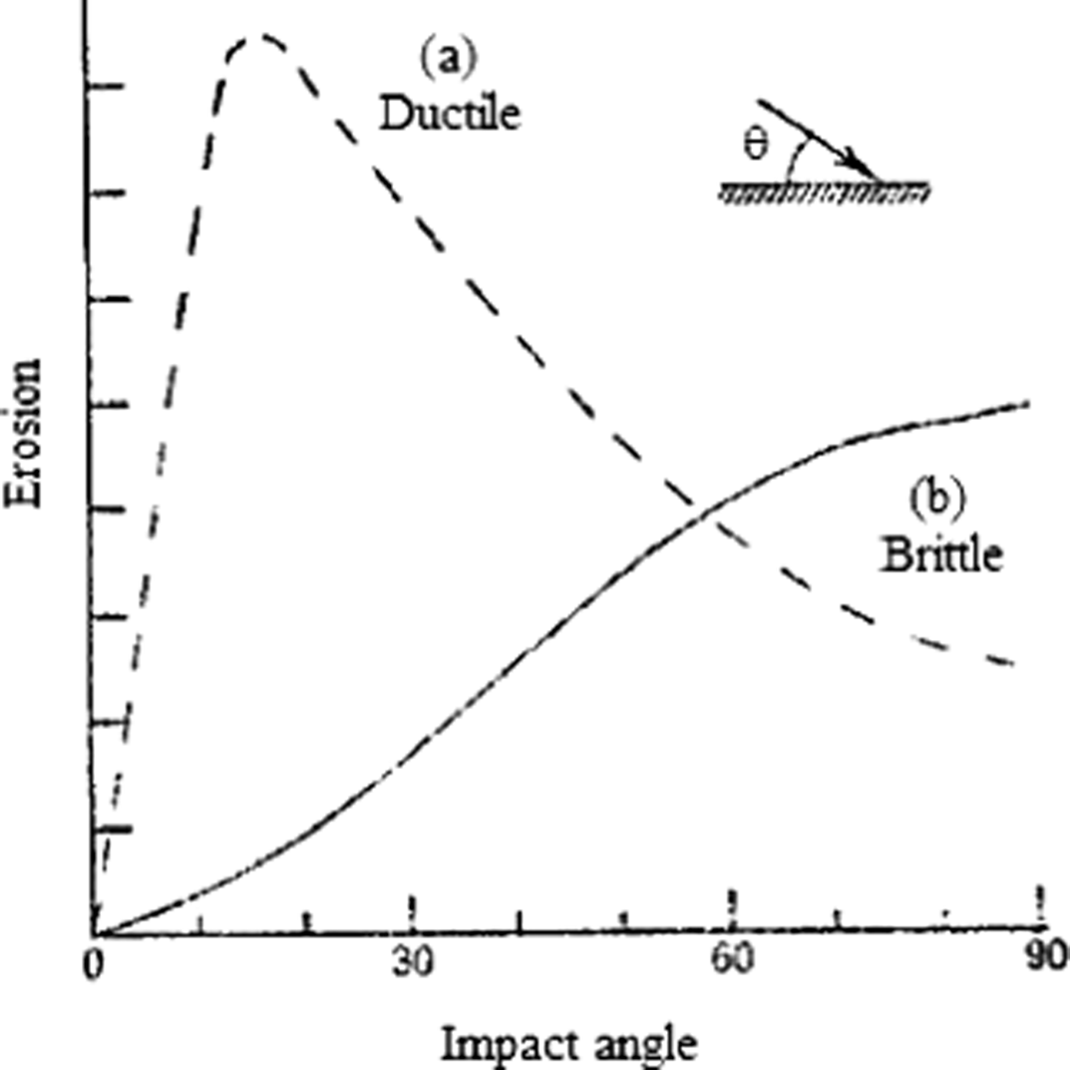
Schematic figure showing variation in erosion with impact angle for ductile and brittle material behaviour. 32
When the graphs formed as a result of our experimental study are investigated, it is found that the maximum erosion rate occurs at 30° angle of the abrasive particles. The erosion rate seems to decrease as the striking angle increases. This is a typical erosion wear behaviour encountered in ductile materials. 33,34
In previous studies conducted on ductile materials, it was found that the value of maximum wear is between two and three times higher than the values of wear formed on normal impingement angles. 35 In our study, apart from observing similar situation, it was found that the impact velocities and sizes of abrasive particles have greater effects on erosion rate too.
The increase in impact velocity led to the increase in the wear rate. The remarkable increase in the wear rate is correlated to particle sizes used in the tests. It is therefore concluded that abrasive particles have more effects on erosive wear rate than the impact velocity.
Figure 7 shows the photographs of test specimens that were subjected to 1000 μm diameter SiO2 abrasive particle bombardments at impact velocities of 23 and 53 m/s. By looking closely at the photographs, it is seen that there is an increase in the deformation of the test specimen surfaces as the impact velocities increase. Moreover, when comparison is made in terms of the impingement angles, the specimens that were stricken at between 15° and 30° seem to exhibit deeper erosion marks on the surfaces. The marks tend to be mild as the angle increases.
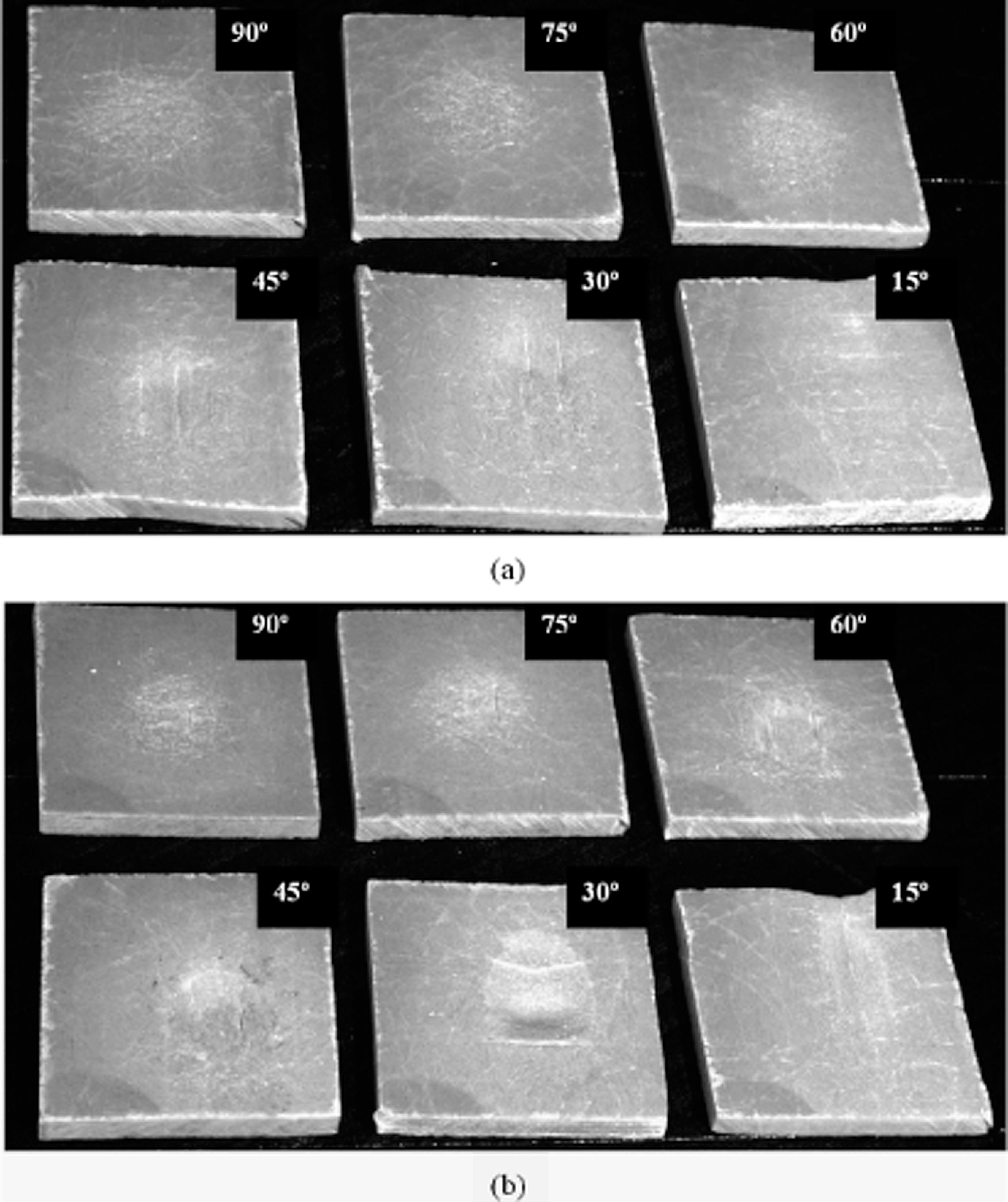
Optic microscopic photographs showing test specimens stricken by abrasive particles with an average diameter of 1000 μm at six different impingement angles (15°–90°) at (a) 23 m/s and (b) 53 m/s.
Figure 8 shows the optic microscopic photographs of test specimens stricken by SiO2 abrasive particles with average diameter of 250 and 1000 μm at constant impact velocity (34 m/s). In this situation also, where the effects of abrasive particles at a constant impact velocity was investigated, it was found that the surface damage tends to increase as the particle sizes got bigger. The variations in the impingement angles were also studied here and deep marks were observed at low angles (15°–30°). The marks decreased as the angles increased.
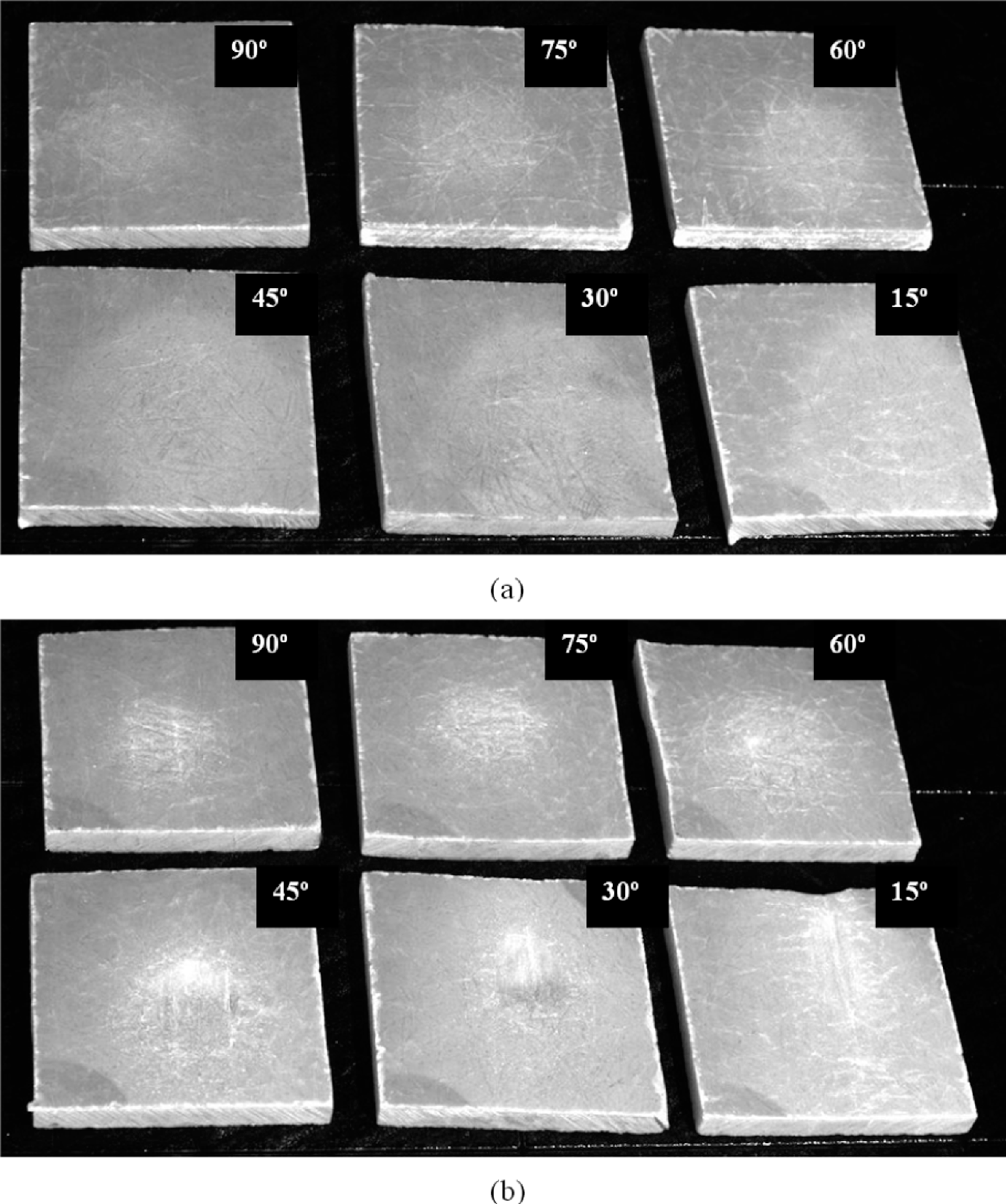
Optic microscopic photographs showing test specimens stricken by abrasive particles at a velocity of 34 m/s at particle diameters of (a) 250 μm and (b) 1000 μm.
The pictures show that the material removal took place at several steps. Initially, microcracks were formed on the surface during the particle bombardments and then the surface layer on the matrix was displaced as the particles continued to strike. The interface between the matrix layer and the mat had undergone damages as the particle bombardments persisted. The matrix layer was then separated from the mat as a result of this damage. The continuous flow of particles led the way to increased fractures on the mats, which consequently intensified deep cracks and wear debris. From investigation of the microscopic photos, the cracks and debris seemed to increase in depth as the abrasive particle sizes increased parallel with the impact velocities.
Steady state erosion
Materials erosion wear behaviour can be classified as ductile and brittle erosion, although this grouping is not definitive. Thermoplastic matrix composites usually exhibit ductile behaviour with their highest erosion rate at around 30° impact angle because cutting mechanism is dominant in erosion while the thermosetting ones erode in a brittle manner with the peak erosion occurring at normal impact. However, there is a dispute about this failure classification as the erosive wear behaviour depends strongly on the experimental conditions and the composition of the target material. 36 To characterize the erosion morphology as received and eroded surfaces with the mode of material removal, the eroded samples are observed under scanning electron microscope (SEM). Figure 9(a) shows the dominance of microchipping and microcracking phenomena. It can be seen that the multiple cracks originate from the point of impact, intersect one another and form wear debris due to ductile fracture in the fibre body. After repetitive impacts, the debris in platelet form is removed and account for the measured wear loss. The occurrence of peak erosion rate at 30° impact is understandable. In this case, both abrasion and erosion processes play important roles. The sand particles after impacting slide on the surface and abrade while dropping down. The wear and, subsequently, the damage are therefore more than that in the case of normal impact. Marks of microploughing on the ductile polyester matrix region seen in Figure 9(a) support this argument. Figure 9(b) shows the local removal of resin material from the impacted surface resulting in the exposure of fibres to the erodent flux. This micrograph also reveals that due to sand particle impact on fibres, there is formation of transverse cracks that break these fibres. On comparing this microstructure with that of the same composite eroded at a higher impingement angle (90°), it can be seen that the breaking of glass fibres is more prominent (Figure 9(c)). It appears that cracks have grown on the fibres giving rise to breaking of the fibres into small fragments. Furthermore, the cracks have been annihilated at the fibre matrix interface and seem not to have penetrated through the matrix. Change in impact angle from normal to oblique alters the topography of the damaged surface very significantly.
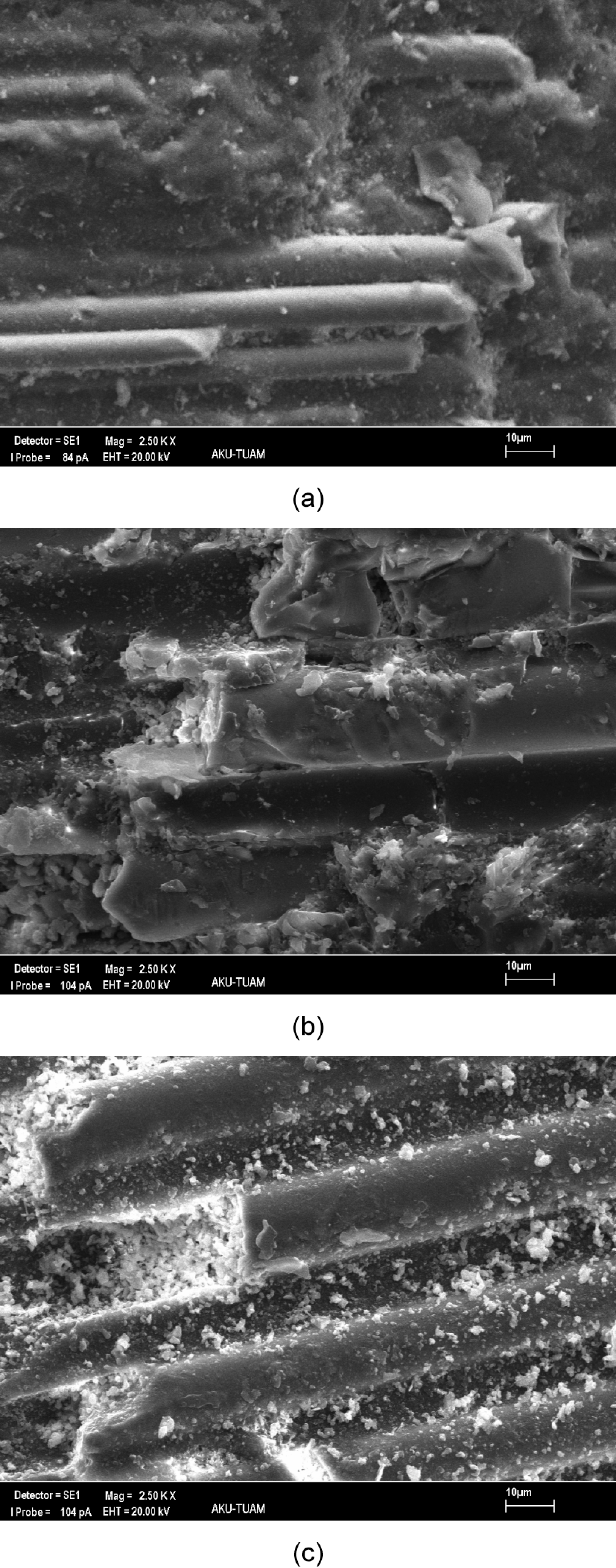
SEM views of test specimens: (a) 30°, (b) 60° and (c) 90° (34 m/s particle impact velocity and ≈500 μm average particle diameter).
Morphology of eroded surfaces
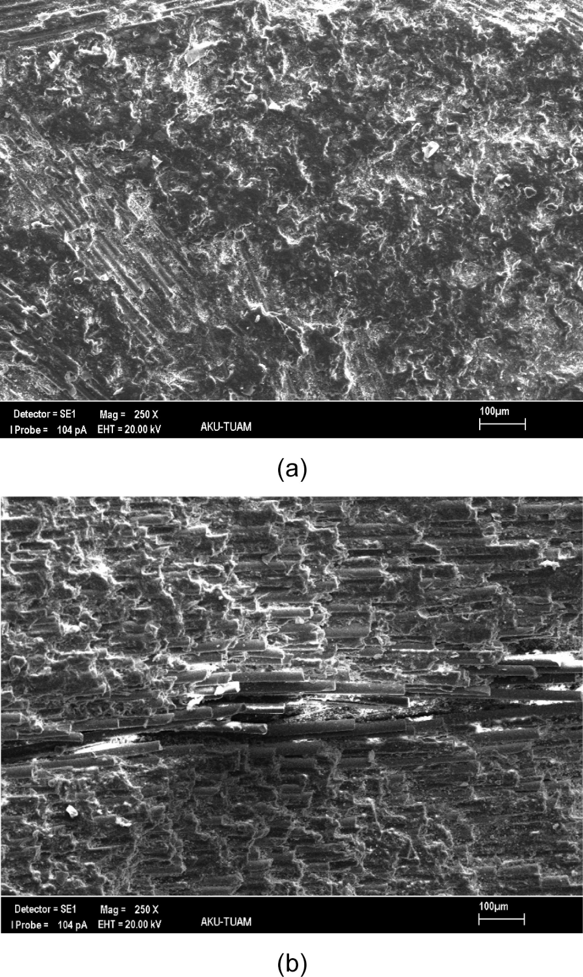
Figures 10 and 11 show SEM views of the test specimens. The views show variations in erosive wear caused by the differences in impact velocities and particle sizes. Figure 10(a) shows variation on test specimen where abrasive particles having diameters of approximately 1000 μm strike the surfaces of test specimens at 23 m/s. Scratch marks were observed on the surfaces of the specimen. This can be explained as being the cause of specimen deformation as a result of particle bombardments. By keeping all other variables constant, the velocity was increased from 23 to 53 m/s, and the test was conducted. Then the SEM views seen in Figure 10(b) were obtained. Apart from the scratches on the specimen surfaces, the increase in the impact velocity led to the formation of debris on the surfaces. This caused deeper scratches and hence increased wear, thereby worsening the condition to a critical state.
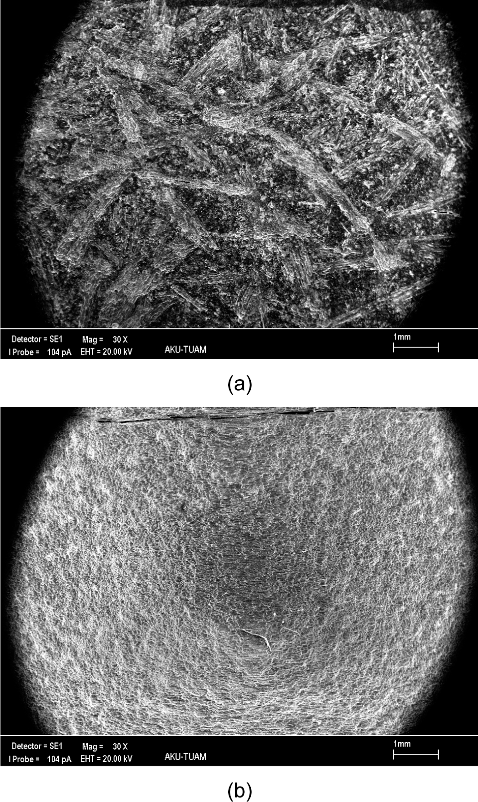
SEM views of test specimens: (a) 23 m/s and (b) 53 m/s (30° impingement angle and ≈1000 μm average particle diameter).
SEM views of test specimens: (a) ≈250 μm and (b) ≈1000 μm (30° impingement angle and 34 m/s particle impact velocity).
The fundamental factor that causes negative effects on erosive wear at an increased striking speed of particles is the change in the kinetic energy of the particles. That is, at higher speeds and hence at higher kinetic energies of the particles, the abrasive particles that strike the surfaces of the composite material fracture the matrix more easily and thus leading to intensified fracturing of the fibres. From the SEM views given in Figure 10, the deformation on the surfaces of the test specimens subjected to abrasive bombardments at striking speed of 53 m/s seems to be more vivid. In other words, deeper grooves are formed on the surfaces of the test specimens as a result of the particle strikes and that the fractured fibres are at more noticeable sizes. At particles striking speed of 23 m/s, the specimen surfaces exhibited only mild variations with shallow grooves.
Figure 11(a) shows SEM views of test specimens taken after being subjected to erosive wear tests at 34 m/s impact velocity and 30° impingement angles of abrasive particles with average diameter of ≈250 μm. In Figure 11(b), the SEM views are given when the velocity and impingement angles are kept constant at 34 m/s and 30°, respectively, where the particle diameters are ≈1000 μm. The two photographs, when studied, seem to have experienced local gaps as a result of particle strikes. But larger particles seem to have caused severe negative effects on the test specimens. This can be seen on the SEM views when looking at the damaged fibres. From these SEM views, which were obtained as a result of bombardments of particles having two different sizes of 250 and 1000 μm, it is found that the increase in particle sizes leads to a decrease in wear resistance. That is, as the striking particles get larger they tend to exert more potential energy onto the specimen surfaces and cause extensive damage on the specimens. Consequently, the increase in both striking speed and particle sizes causes substantial changes in wear rates.
Conclusions
The following conclusions have been obtained from this study. Maximum erosion rate is observed at 30° impact angle. However, parallel to the increase in an impingement angle, the values of erosion rate drop. This is a typical erosion wear behaviour encountered in ductile materials. The increase in impact velocity leads to an increase in erosion rate. The remarkable increase in the erosion rate is correlated with particle sizes used in the tests. Moreover, changes in abrasive particle size bring about more effects on erosive wear rate than changes in impact velocities. Looking closely at the optical microscopic and SEM views, it is seen that there has been an increase in deformation of the test specimen surfaces as the impact velocities and abrasive particle sizes increase. In addition, adverse effects can be seen at small impingement angles (15°–30°).
Footnotes
Funding
This research received no specific grant from any funding agency in the public, commercial, or not-for-profit sectors.