
Abstract
Reinforcing structures using bonded composites is an effective and economic method to increase the service life of damaged structures. In this study, we use the finite element method to analyze the behavior of a laminated structure by computing the stress concentration factor and the stress intensity factor at the crack tip in mode I. The effects of the mechanical properties of the laminate layers and the adhesive layer on the behavior of the assembly are highlighted. The results show that the factors of concentration and stress intensity are affected by the orientation of fibers and the presence of geometrical defects. The magnitude of the latter affects and amplifies the stress concentrations at the crack tip.
Keywords
Introduction
Bonded composite material on the external side was recognized as an effective method to repair the cracks and increase the service life of structures. 1–4 The determination of the stress intensity factor (SIF) at the crack tip is one of the possible ways for the analysis of the performances of the composite material reinforcement. The repair of the cracks by bonded composite has proved its effectiveness to reduce the stress intensity at the crack tips. 5,6 This method is also used to repair decayed aircraft components.
An aircraft is subjected to severe aerodynamics and structural stresses that can result from repeated landings and takeoffs and degradations due to the environment such as stress corrosion. Stresses can cause damage, weakening or ageing of the aircraft structure by affecting its capacity to withstand the load. Considerable research has been conducted to develop the technology of bonded composite patch in aeronautical structure. 2,5,6 However, with the development of powerful computers, numerical modeling has been used to understand the effectiveness of repair and to improve its design. Reinforcement offers several advantages such as improvement of the material life span in fatigue, reduction of corrosion and easy adaptation to a complex aerodynamic contour. Several authors have been using the finite element method to calculate the SIF of reinforced crack heads. 7–10
Studies were carried out on crack emanating from the side semicircular notch repaired by a semicircular composite patch in mode I and pure mode II. 11–13 In the same context, the comparison of the results of cracks repaired with an octagonal composite patch with various heights was the object of a study by Ouinas et al. 14 The same authors 15,16 showed the influence of the disbond on the amplification of the stress concentrations factor at the notch root and of the SIF at the crack tip. The criteria of rupture were applied to, on one hand, a point to predict the cohesive failure 17 and out of plane, on the other hand, to predict the adhesive failure 18 using the finite element method. Two- and three-dimensional finite element methods have been used to analyze the bonded repair of cracked panels. 5,6,19,20 Since the adhesive thickness is a lot smaller than the cracked plate and bonded patch thicknesses, the three-dimensional finite element mesh of the bonded repair of cracked panel requires extensive elements number. The three-layer technique is used for the analysis of the cracked structure reinforced with composite patches. 19,21 After a cracked structure is repaired, force transfer occurs between the cracked structure and the composite patch through the adhesive layer. The strain energy release rate at the crack tips is highly reduced, 5,6,22 and the SIF exhibits an asymptotic behavior as the crack length increases.
Papanikos et al. 23 used a finite element-based progressive failure model to investigate the geometrical effects on patch debonding initiation and progression induced by mechanical loading. They used a metallic sheet containing a central through-thickness crack loaded in tension and repaired using a double-sided rectangular-tapered composite patch. The behavior of repaired cracked aluminum plate in case of full-width disbond was investigated by Ouinas et al. 24 They highlighted the disbonds of various sizes and situated at different positions with respect to the crack tip as well as the effect of adhesive and patch thickness on repair performance. They concluded that the crack growth rate is dominated by the SIF near the location and size of the preexisting disbonds. They indicated that the cracked plate and disbond propagation result in an increase in the patch deformation. They also express that the patch does not have an influence on the crack growth when the crack length/patch diameter ratio exceeds 0.8. Khalili et al. 25 experimentally investigated the response of edge-cracked aluminum specimens repaired with single-sided composite patches subjected to Charpy impact loading. They concluded that the effect of stiffness ratio is significant in absorbing energy in composite patches. For small stiffness ratio, the patch cannot effectively reinforce the cracked plate in in-plane impact load.
In the present study, two cases were analyzed. The first case concerns an analysis of two compositely bonded layers and the second case deals with three layers with an aluminum alloy middle layer. In most of the cases studied, many researchers used a local reinforcement by patch; whereas in this case, we performed a total reinforcement of the structure. In this analysis, the notch effect, the evolution of the stress concentration factor (SCF) and the variation of SIF of a crack emanating from the notch are highlighted. The geometrical defect is characterized by the stress concentration, which favors the initiation and propagation of crack. For this purpose, the influence of fiber orientation of the composite material, adhesive shear modulus, adhesive thickness and laminate thickness on the variations of the SCF and the SIF are examined using the finite element method.
Geometrical model
For modeling purposes, a laminate in boron/epoxy with a side semicircular notch is considered (Figure 1). The dimensions of the laminated plate are length h = 280 mm, width w = 180 mm and thickness e
s = 1 mm. The considered assembly is requested in uniaxial traction in the vertical direction under the applied stress of amplitude σ = 100 MPa. The plates are bonded on all the covering lengths with an FM 73 adhesive of shear modulus
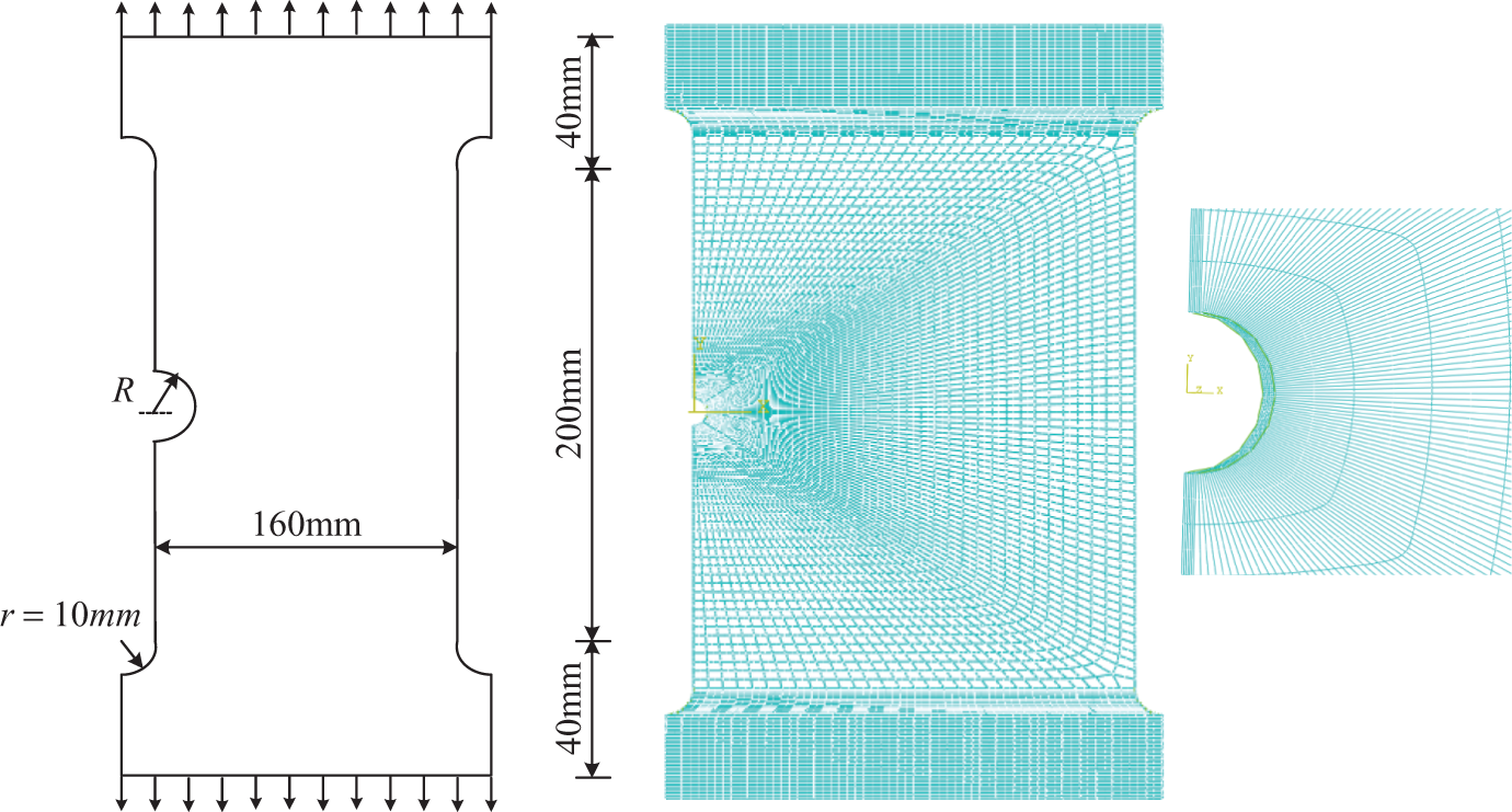
Geometrical model and typical mesh of the assembly.
The mechanical characteristics of composite material with the orientation of fibers θ = 0° are
Longitudinal Young modulus
Transversal Young modulus
Shear modulus
Poisson’s ratio
The commercial code of finite elements Abaqus Version 6.9.1 26 was used for all calculations. We used 42,852 quadrilateral elements hexahedral and 198,247 nodes of type C3D 20R with a refined and structured mesh in the vicinity of the notch as shown in Figure 1. In the presence of crack, the number of the quadrilateral elements reaches 29,617 of type CPS4R and 812 triangular elements of type CPS3. The singularity at the crack head can be integrated in the solution by replacing the elements at the crack head by quarter-point special elements. 27
Case of two bonded layers
Stress concentration factor at the notch root
In this section, the SCF at the side semicircular notch in two bonded layers is determined. Figure 2 presents the variation of the Kt notch root in each layer as a function of notch radius. The orientation of fibers of the first layer is θ = 0° and that of the second layer is perpendicular to the first layer at an angle θ = 90°. It can be seen that the SCF increases with notch radius of the second layer (θ = 90°), but the rate of increase in the first layer (θ = 0°) is not very significant. It is also noted that the SCF is very important in the second layer where the ply orientation is 90° in comparison with the first layer. In the first layer factor, Kt is lower than 0.3; and in the second layer, it is higher than 2. It means that at the notch root of the second layer, there is a stress concentration; and in the first layer, there is a stress relaxation. This behavior can be explained by the fact that there is absorption of stress by the most resistant layer along the longitudinal direction where the fibers are parallel to the loading direction. The risk of crack initiation is then more important in the second layer.
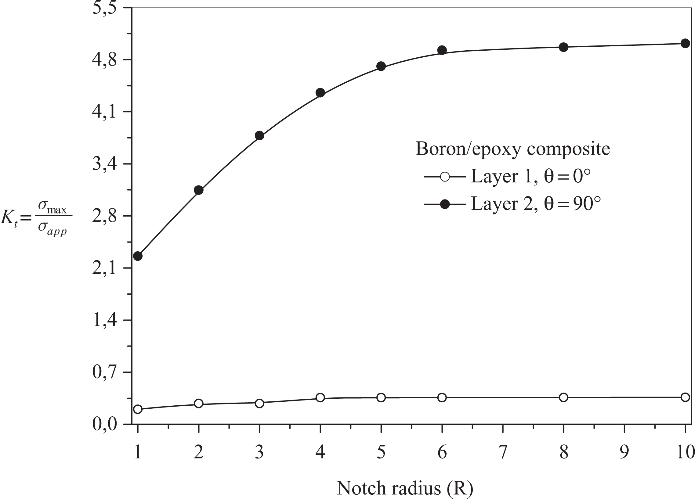
Variation of Kt versus notch radius.
In order to confirm the above results, the variation in the SCF Kt was determined and is shown in Figure 3 in the two layers against fiber orientation of the second layer. The angle θ of the first layer was maintained constant, that is, perpendicular to the direction of stress (θ = 0). When the two angles of fiber inclination are equal to 0, the SCF for the two layers is identical whatever be the notch radius value.
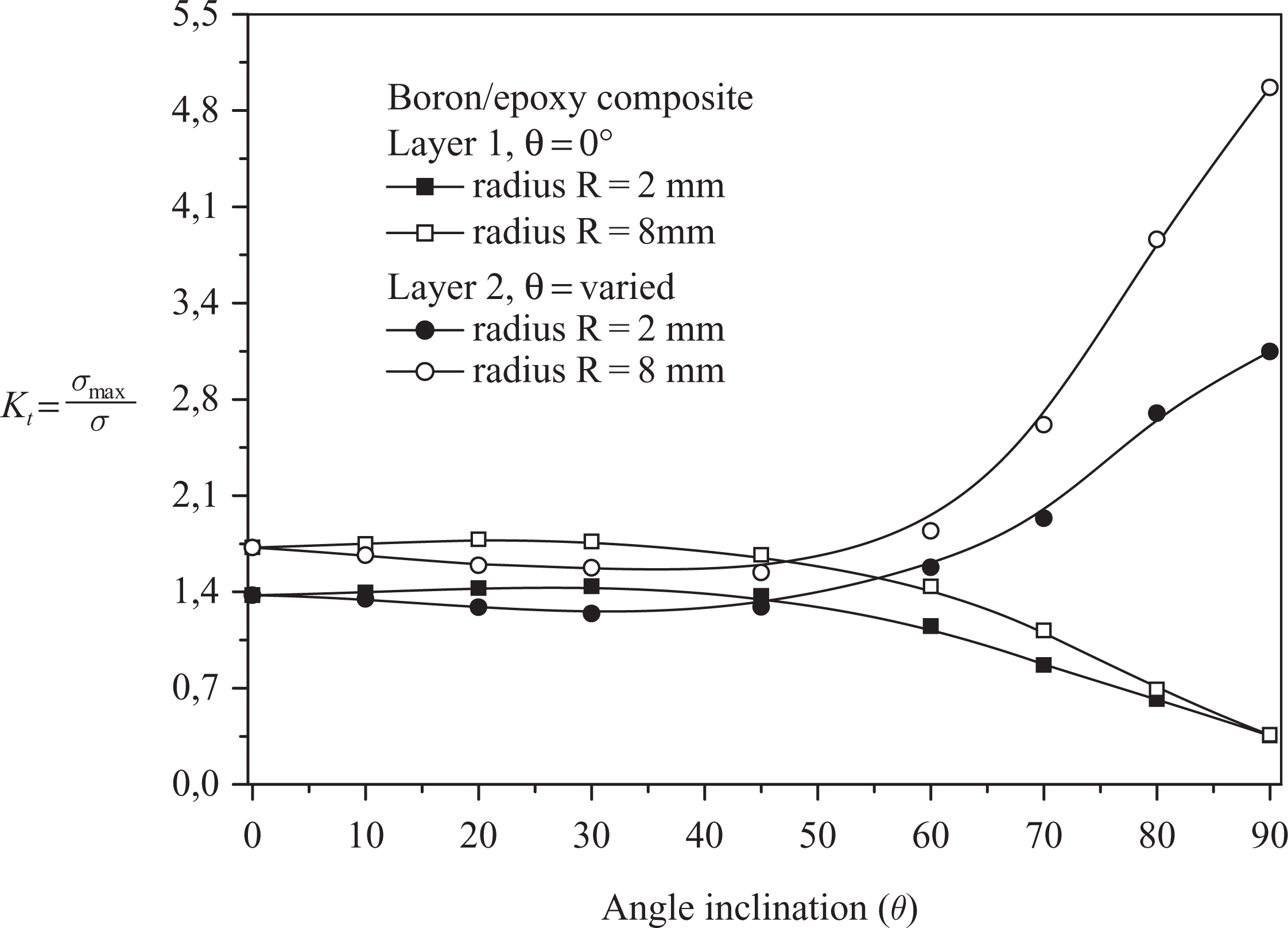
Variation of the Kt versus angle of fibers orientation.
The SCF Kt is about 1.4 and 1.75 for the notch radius R = 2 mm and R = 8 mm, respectively. Ouinas et al. 10,28 observed that when the notches radius in a homogeneous material varies between 2.54 and 12.7 mm, the variation in the SCF lies between 2.86 and 3.016 for the circular notches and between 3.068 and 3.3 for the semicircular notches. The stress concentration at the notch root is more important in the adhesively bonded laminated composite compared with that of isotropic materials, if the ply orientation tends toward the direction of the applied load. It is less important in the laminate in comparison with isotropic materials if the ply orientation is perpendicular to the applied load.
One can also see in Figure 3 that factor Kt in the first layer increases asymptotically as the angle of the fiber orientation in the second layer decreases. The asymptotic value is approximately 1.4 and 1.75 for the radius R = 2 mm and R = 8 mm, respectively. The stress at the notch root of the first layer decreases when the ply orientation of the second layer increases. With regard to the second layer, one shows in Figure 4 that Kt increases exponentially starting from the inclination angle of the fibers θ = 45° and is stabilized toward a slightly asymptotic value when the angle of the fibers is lower than 45°.
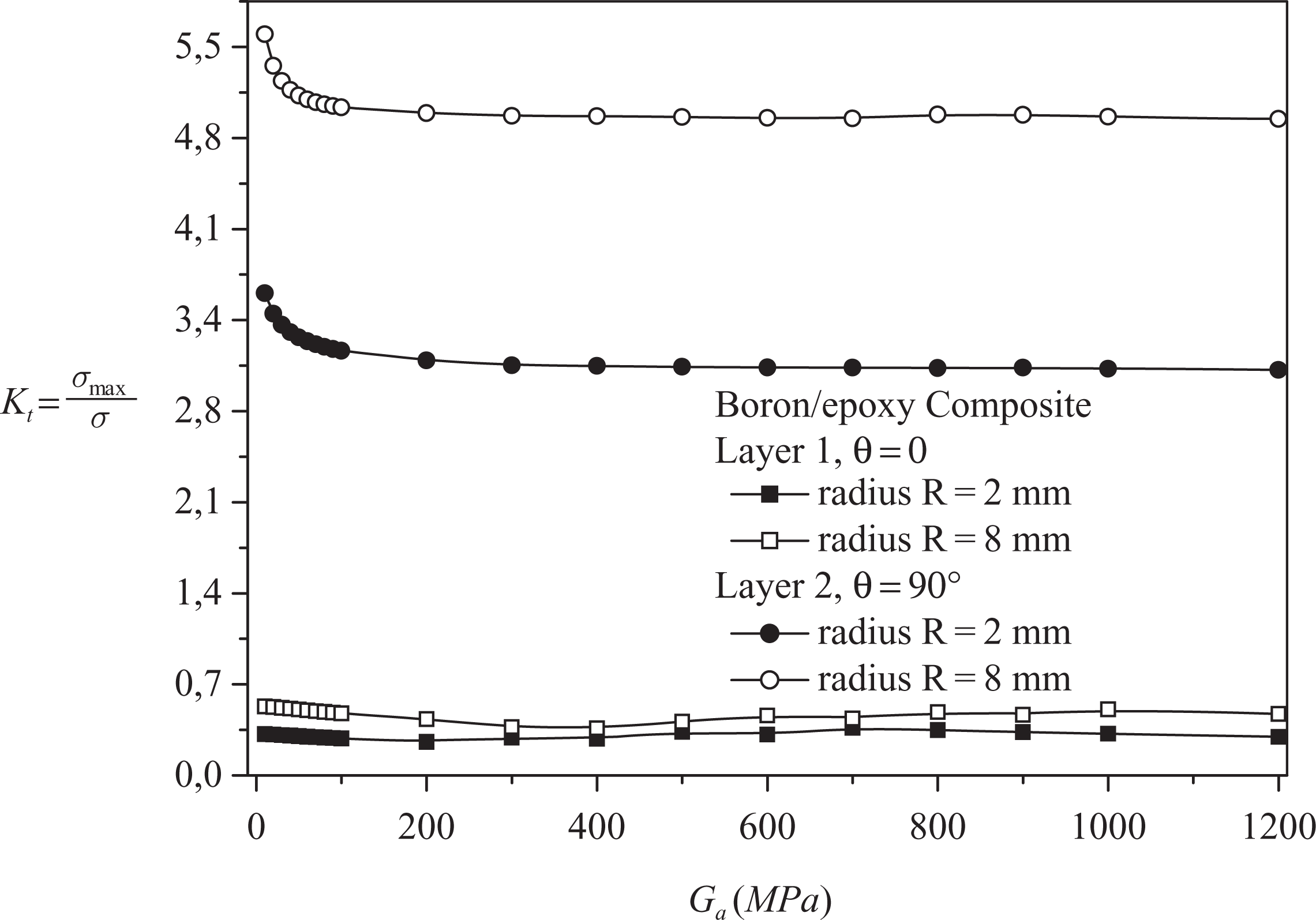
Variation of the Kt versus adhesive shear modulus Ga .
Effect of adhesive shear modulus
The adhesive shear modulus is an important characteristic influencing the mechanical properties of the assembly. In the case of the laminate structures, the adhesive transmits most of the stresses to the layers. Figure 4 shows the influence of the adhesive shear modulus on the evolution of the SCF Kt
in two bonded layers in the presence of various semicircular notches of radii R = 2 mm and R = 8 mm. The fiber orientations in the first and second layer are, respectively, θ = 0 and θ = 90°. The adhesive thickness is
Effect of the adhesive thickness
The thickness of the adhesive layer represents an important geometrical parameter influencing the rupture of the laminate structures. The latter become increasingly adhesive when the thickness increases. The resistance of the adhesive joint decreases when the thickness of the film increases. The analysis by the finite element method enabled us to determine the variation in the maximum stress at the notch root as a function of the adhesive thickness layer for two semicircular notches R = 2 mm and R = 2 mm (Figure 5). Also, the SCF is given in two layers perpendicular to the fiber assembly.
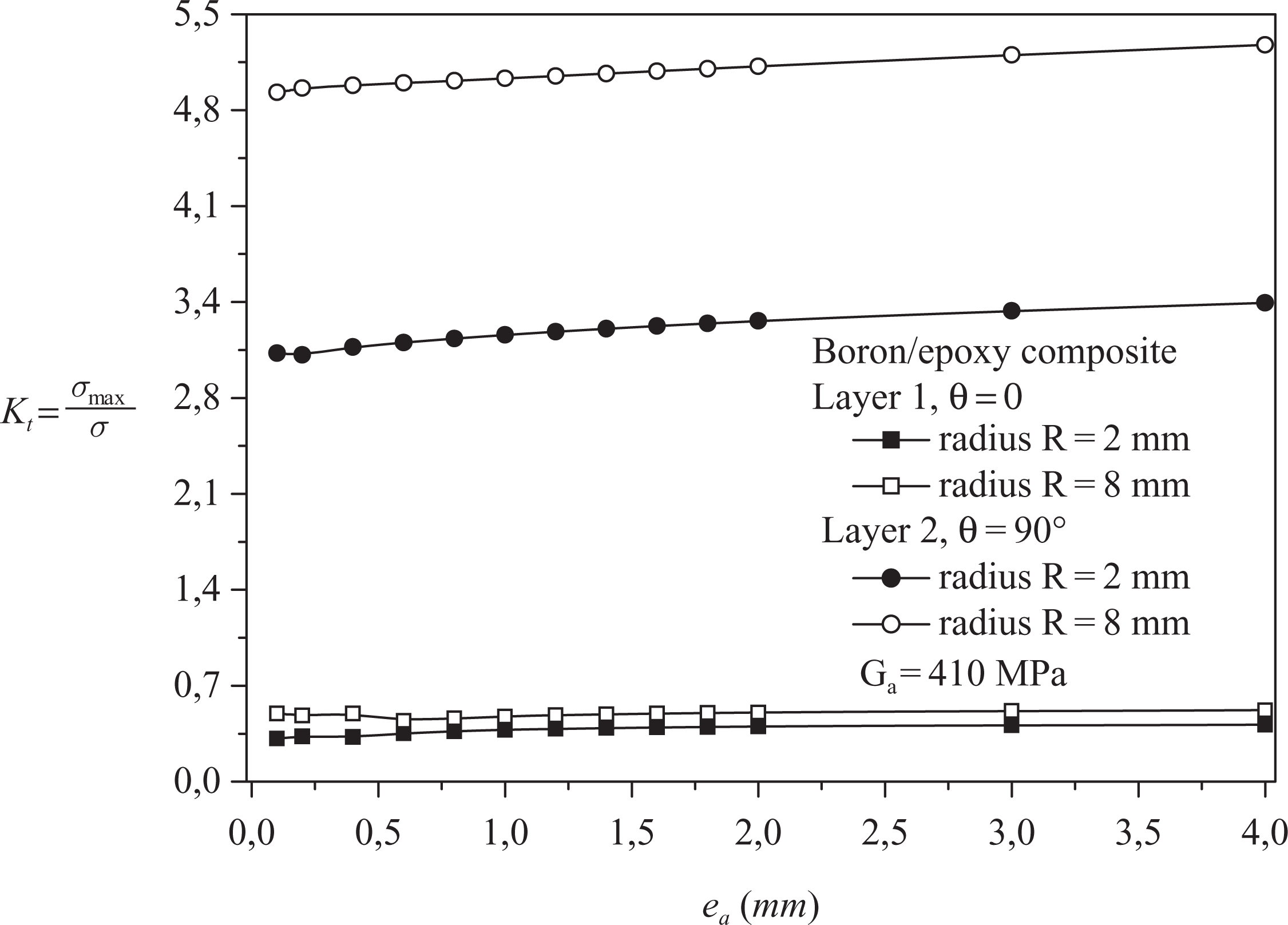
Variation of the Kt versus adhesive thickness ea .
It is noted that the SCF is quasi-stable when the adhesive thickness increases. Consequently, the SCF increases significantly with the increase in the semicircular notch radius, especially, in the layers whose fibers are parallel to the direction of the applied load. One can conclude that the effects of the adhesive thickness on the variation of the SCF at the notch root in the laminates are negligible. Thus, the factors obtained for the directed layer at 90° are clearly higher when compared with those obtained for the layer directed at 0°.
Effect of the plate thickness
The influence of the thickness of the plates on the extent of the SCF is analyzed in this section. Figure 6 shows the effect of the composite plate’s thickness on the variation of the SCF in the presence of a semicircular notch. The SCF increases exponentially with the reduction in the thickness of the composite layer. The elastic energy released by the first notched layer (θ = 0) will be absorbed by the second layer by means of the adhesive. One can see that the increase in the thickness of the layers reduces the SCF at the notch root in a proportional way.
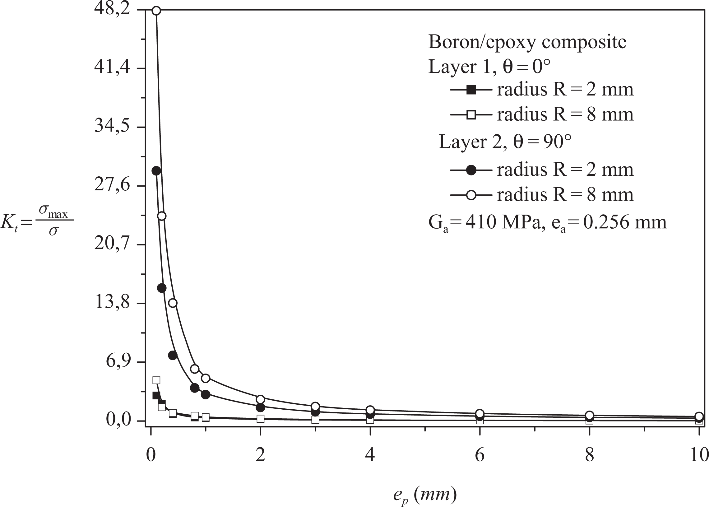
Variation of the Kt versus thickness plate layer ep .
It is noticed that the curve of factor Kt
increases proportionally with the decrease in the thickness of composite layers, whatever be the fiber orientation. This increase is marked much more when the thickness of the layers tends to be a zero value. Beyond the thickness
Stress intensity factor for a crack emanating from notch
In this paragraph, the behavior of a crack emanating from semicircular notch in composite laminates made up of two adhesively bonded layers is analyzed. Two cases are considered, the first one consists in assuming that the crack is in the first layer of the composite, that is, the orientation of fibers is perpendicular to the applied load. For the second, the crack is in the layer whose fibers orientation is parallel to the applied load. Figure 7 presents the variation in the SIF in mode I of a crack emanating from various notches in the first layer (1) where the ply orientation is θ = 0.
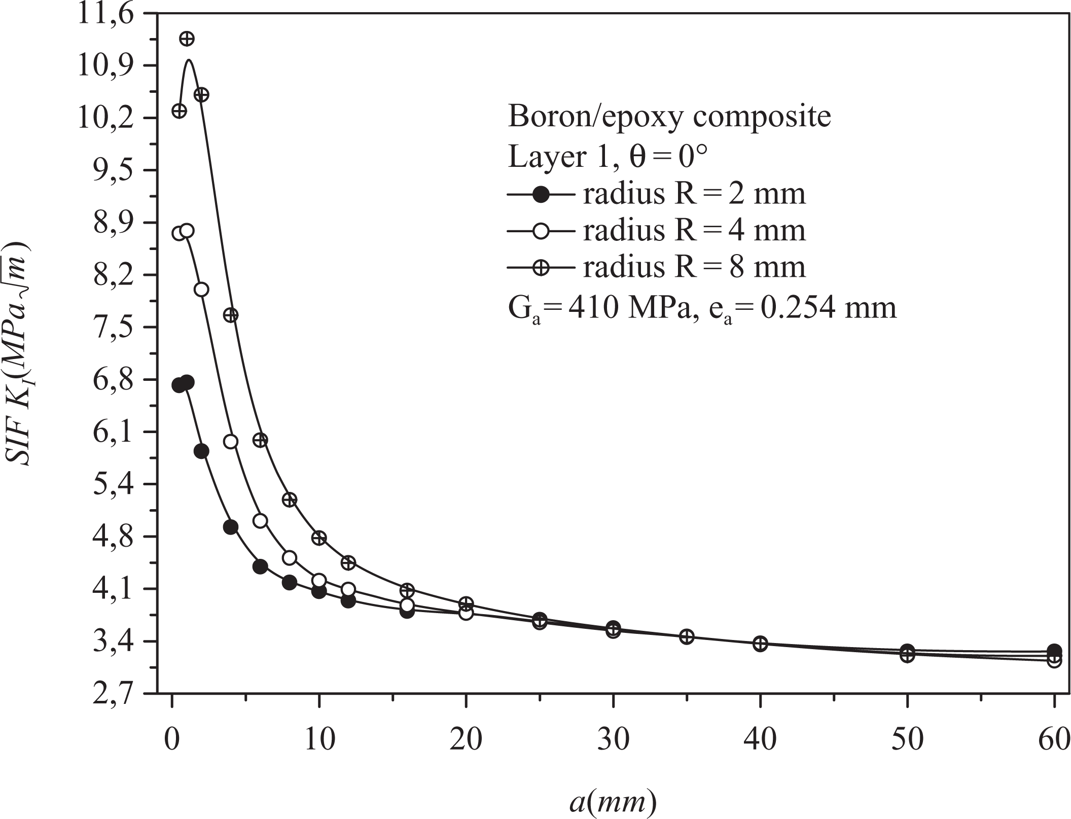
Variation of the stress intensity factor versus crack length emanating from notch of layer 1 (θ = 0).
It is noted that the SIF increases exponentially with the reduction in crack length. Factor KI reaches its maximum for the smallest crack length. It is noticed that the notch effect disappears starting from the crack length a = 2 mm, whatever be the semicircular notch radius. Figure 8 represents the variation in the SIF in mode I as a function of propagation of the crack initiating from various notches in the second layer (2) where the ply orientation is θ = 90°.
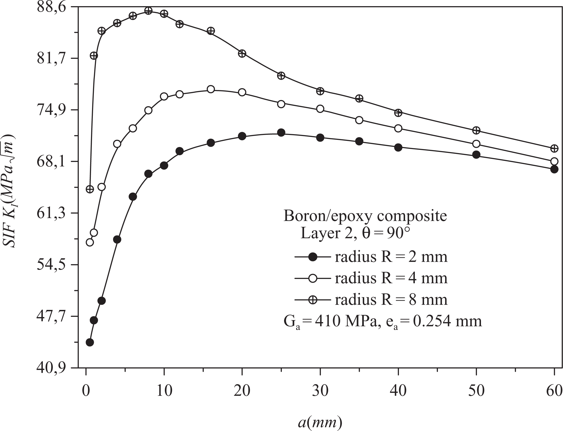
Variation of the stress intensity factor versus crack length emanating from the notch of layer 2 (θ = 90°).
The figure shows that the second layer (2) in the SIF is very large in comparison with the first layer (1). It means that the effect of the mechanical properties on the variation of the SIF is very significant. The latter increases appreciably for the three cases of notch radius when the crack size is lower than 15 mm. Beyond this value, the SIF decreases with increase in crack size. When the crack propagates from notch, it receives a driving force of the stress field that surrounds it, and the energy is greater in the vicinity of the notch. The reduction in the SIF influences directly the crack kinetics.
An important behavior is observed by examining Figure 8. The SIFs shows a decreasing behavior as the crack length increases, whatever be the position of the crack in the laminate. This effect is due to the presence of the adhesive layer. The presence of the adhesive layer leads to a reduction of the SIF at the crack tip in the adherends of the laminate.
Effect of adhesive shear modulus on the SIF
To analyze the effect of adhesive shear modulus on the variation in the SIF of a crack was assumed to emanate from a semicircular notch of length a = 2 mm. The notch radii are R = 2 mm and R = 8 mm, respectively. The adhesive thickness is
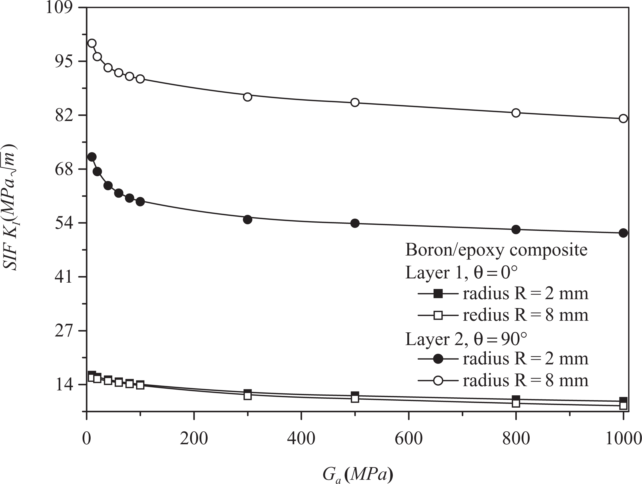
Variation of the stress intensity factor versus adhesive shear modulus Ga .
The reduction ratio is higher in the second layer where the fiber orientation is θ = 90°. A significant effect of the shear modulus on the SIF exists similar to the SCF at the notch root. It can be concluded that a higher value of the shear modulus improves the resistance to the crack propagation in the adherend at the expense of that in the adhesive. Thus, the choice of the shear modulus in the whole laminate must be optimized.
Effect of adhesive shear thickness on the SIF
To highlight the effect of the FM 73 adhesive thickness, we plotted in Figure 10 the variation of SIF of crack emanating from various notches in the two layers of the laminate. It is noticed that the SIF has an inverse behavior compared to its variation against shear modulus. For the second layer, the variation in adhesive thickness has a large effect on the SIF. The SIF does not vary significantly when the adhesive thickness tends to a value double that of the laminate layers. Indeed, the increase in adhesive thickness led to an increase in the SIF at the crack head. The reduction in adhesive thickness improves the resistance to the crack propagation in the adherend but reduces the resistance of adherence, however.
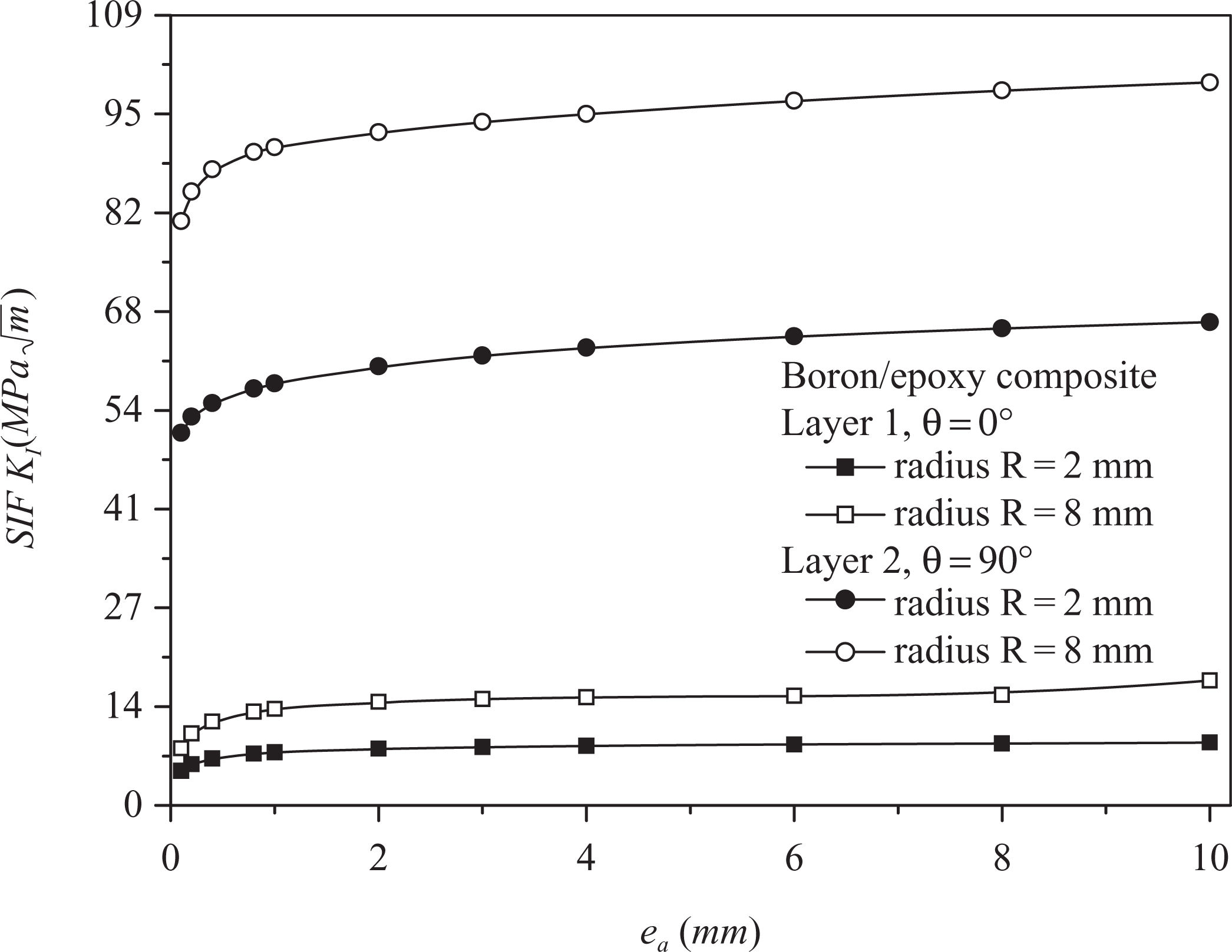
Variation of the stress intensity factor versus adhesive shear thickness ea .
Case of three bonded layers
Stress concentration factor at the notch root
In this section, the SCF at the side semicircular notch in three bonded layers is investigated. Figures 11 and 12 depict the variation in Kt at the notch root in each layer as a function of notch radius for the three following configurations:
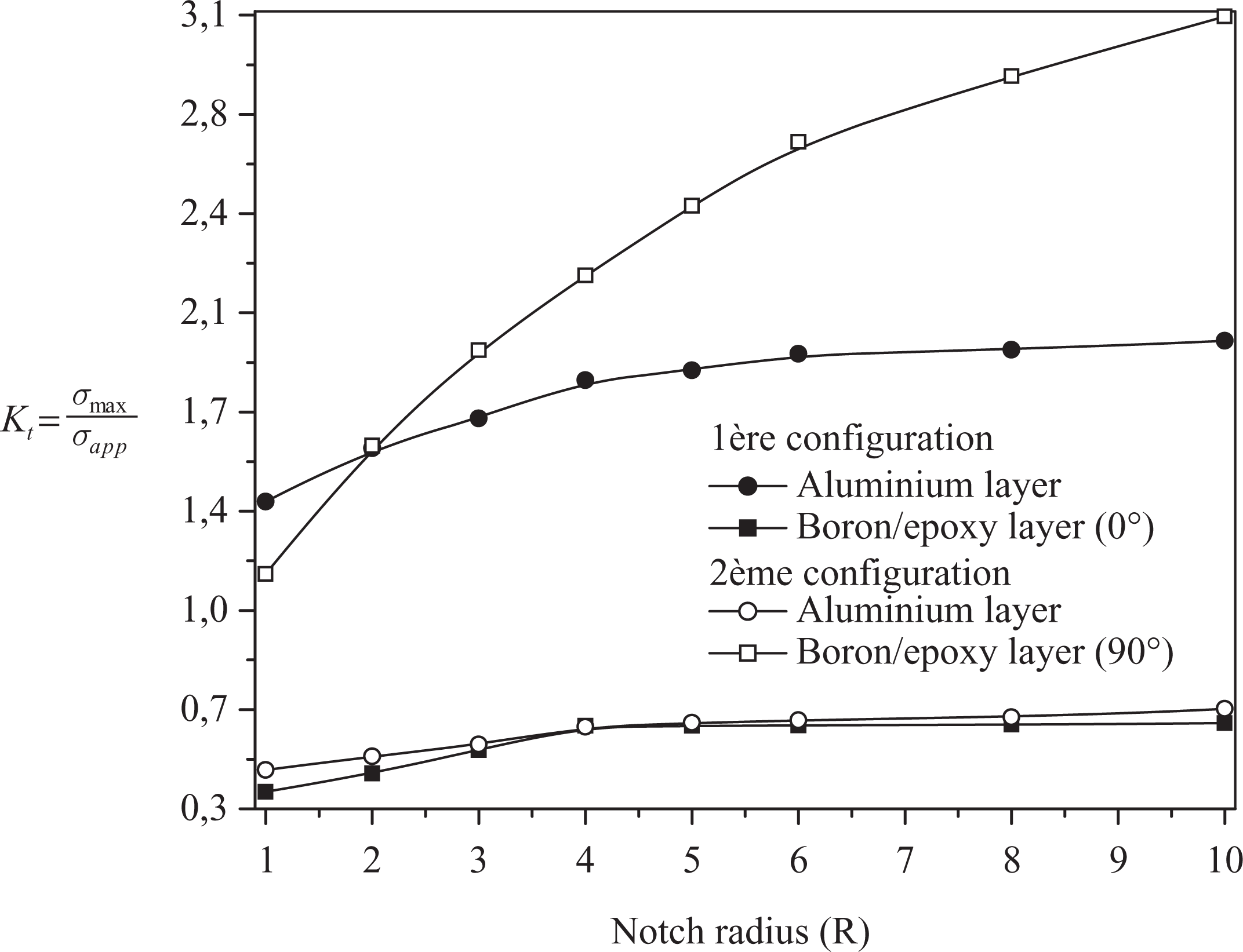
Variation of stress concentration factor versus notch radius.
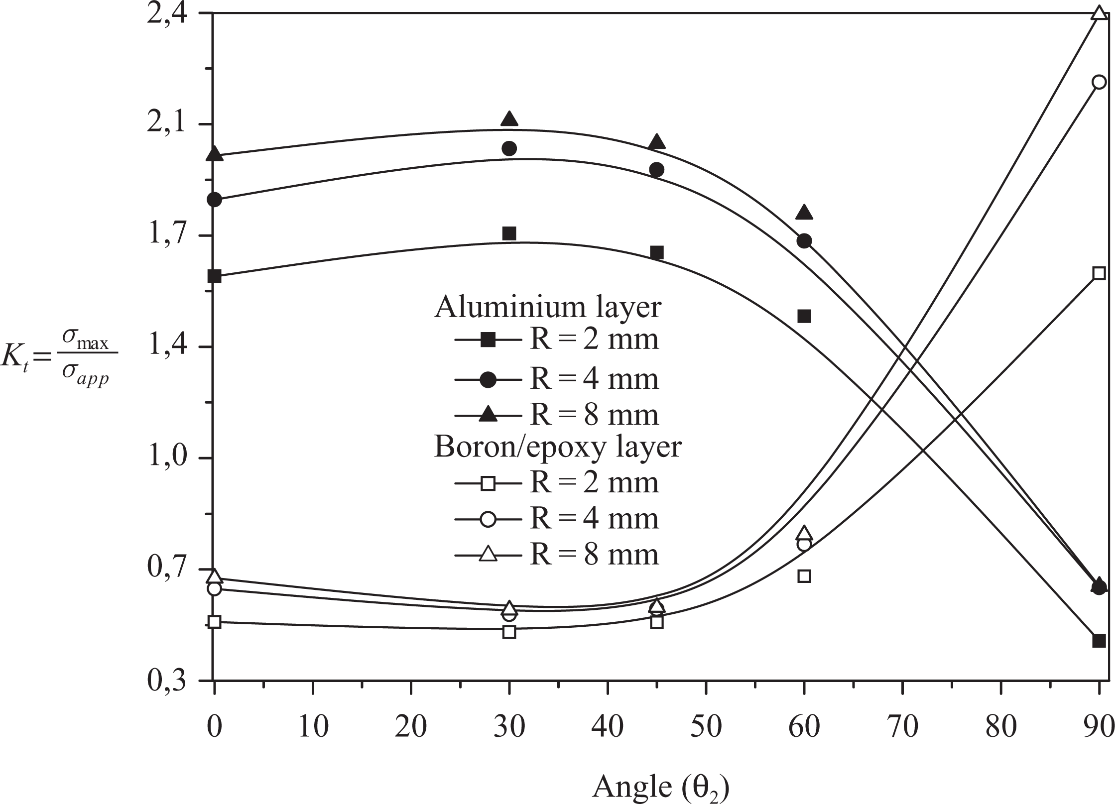
Variation of stress concentration factor versus orientation θ2.
The fibers of the external layers are directed at 0° angle.
The fibers of the external layers are directed at 90°angle.
The external fibers of a layer are fixed at 90° and the fibers of the second external layer variable from 0° to 90°.
First and second configuration
In the first configuration, the fiber orientation of the first and the third layer are at θ = 0° and the middle layer is of aluminum alloy. The results are shown in Figure 11. It can be seen that the SCF increases with notch radius for the three layers. The rate of increase for the composite layers is not very significant. In this case, it is the aluminum layer that absorbs more stress compared to the two layers of the composites.
It is also noted that the SCF is large in the metal layer compared with the composite layer. In the first layer, factor Kt is higher than 1 and larger than in the second layer, where it is less than 1. In the case of the maximum radius (R = 10 mm), the sum of the stress concentrations of the two external layers unfavorably directed relative to the applied load is lower than the stress concentration of the metal layer for the smallest notch radius. It is also noted that when the radius R exceeds the value of 6 mm, one can observe a clear stabilization of the SCF and consequently this parameter exhibits an asymptotic behavior, due to the stresses absorption by the metallic material. The risk of crack initiation becomes more significant.
An inverse behavior occurs when the composite layers are directed favorably with respect to the applied stress. The stress concentrations are higher than 1. The SCF increases quadratically with the notch radius for the composite materials; whereas for the metal layer, a stabilization starting from the radius R = 4 mm occurs. In this case, the composite layer continues to absorb the stress at the notch root. This behavior can be explained by the fact that stress is absorbed by the more resistant layer along the longitudinal direction (where the fibers are directed in the load direction). The risk of crack initiation or delamination is more important in the composite.
To show the effect of fiber orientation on the variation of the SCF, the first layer θ1 was taken equal to 90°; whereas, in the third layer, the orientation of the fibers is variable (θ2 variable). The results of the SCF are shown in Figure 12. It is observed that whatever be the notch radius, the variation in the SCF is similar for the respective layers of aluminum and composite. The SCF obtained for the composite material increases exponentially with angle θ2.
The effect of fiber orientation on the increase of the SCF occurs starting from 45°. For values definitely lower than 45°, the SCF remains stable. An opposite behavior is marked for the aluminum layer. The SCF is stable until 45°, and starting from this value, it decreases proportionally with the increase in the angle θ2, which means that at the notch root of the composite layer, there is absorption of the stress concentration; whereas in the metallic layer, there is stress relaxation.
Variation of the SIF
In this section, we study the variation of the SIF in mode I for two various crack lengths emanating from notch of radius R = 8 mm located in the metal layer between the two composite layers. The laminate is composed of three layers adhesively bonded. The crack lengths are constant (a = 2 mm and a = 10 mm). The influence of the orientation of the second composite layer is highlighted while maintaining the angle of the first layer constant (angle θ1 = 90° and θ2 variable). The results are shown in Figure 13. It can be noted that whatever be the fiber orientation of the second composite layer, the SIF is almost stable up to the value of θ2 = 50°, beyond which a reduction is noted until angle θ2 = 90°.
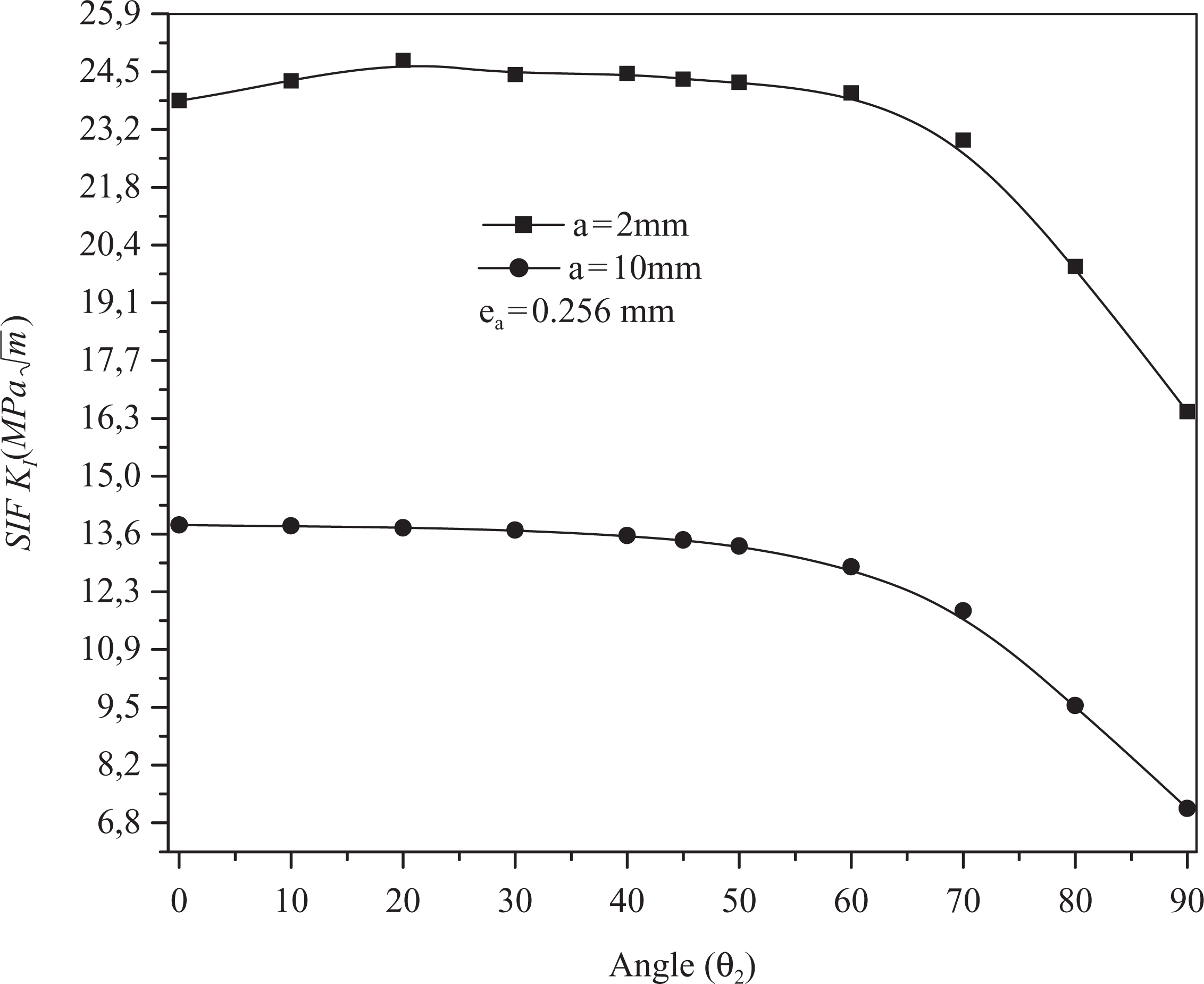
Variation of the stress intensity factor versus orientation θ2.
Thus, the maximum reduction of the SIF is obtained when the fibers are parallel to the applied load direction. It can be said that the importance of SIF reduction is strongly dependent on crack size. The larger the crack length, the relatively more important the reduction is. This is explained by the fact that the small cracks are requested in the stress field generated by the semicircular notch. To confirm these results, the evolution of the stress concentrations in the composite layers is shown in Figure 14. It is noted that the evolution of the SCF at the notch root of the composite layers is almost stable until θ2 = 50°; whatever be the fiber orientation (θ1 = 0° or θ2 = varied), it increases or decreases with the increase of θ2. The layer whose fibers are directed at 90° withstands more loads, which are transferred from the cracked aluminum layer toward the composites through the adhesive film.
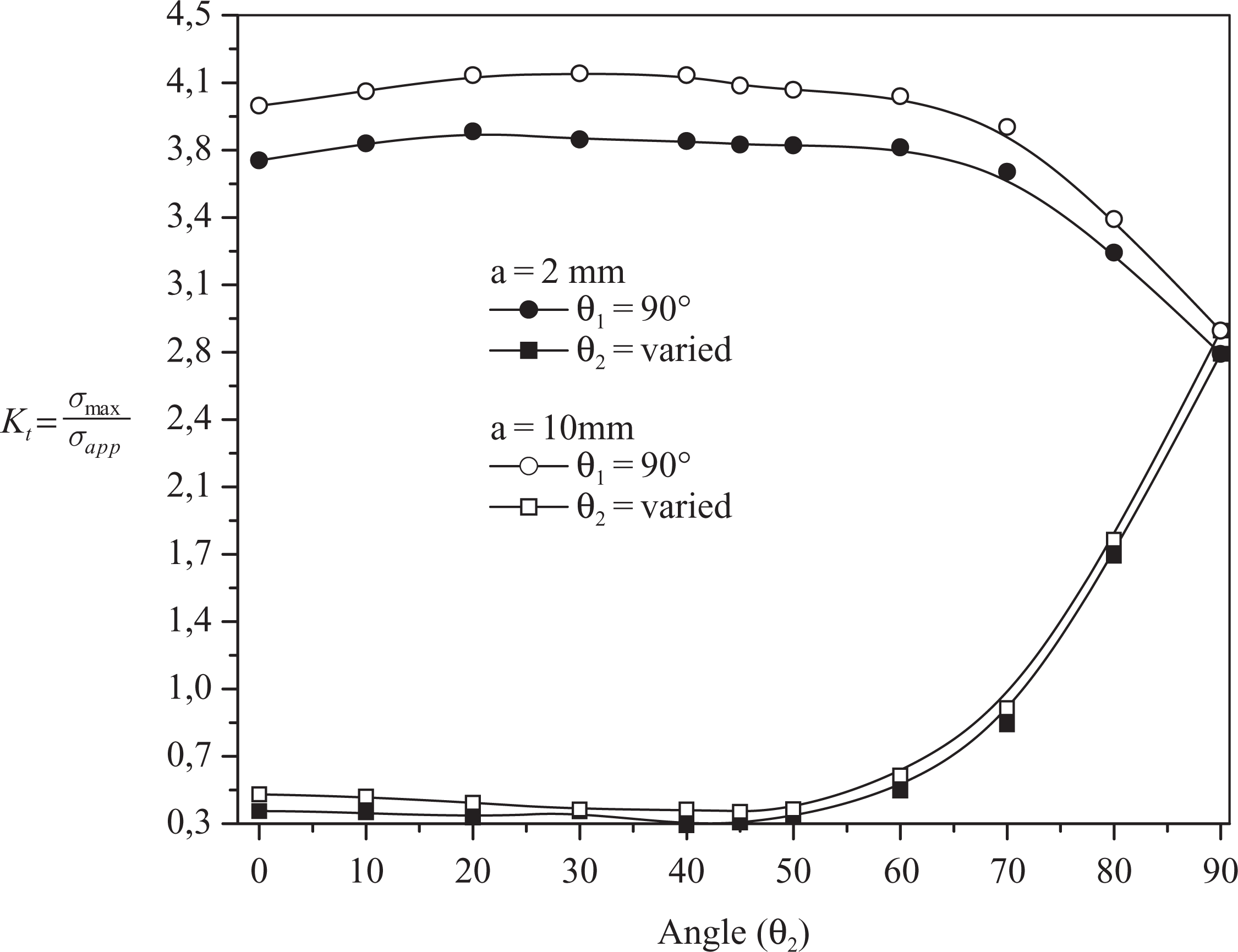
Variation of the stress concentration factor versus orientation θ2.
As θ2 tends toward 90°, the stresses equilibrate on the two composite layers. The stresses at the notch root are equitable when the fibers of the two layers are parallel to the applied stress, leading to the reduction in the SIF at the reinforced crack tip. At θ2 = 0, the 90° oriented layer withstands 86% of the stress concentrations produced at the crack tip of length a = 10 mm. This proportion tends to increase for the small crack lengths. It is 90% for a = 2 mm. This is due to the stress field generated by the notch effect.
Figure 15 shows the variation of the SIFs versus crack length for several laminate fiber orientations. The notch radius is R = 8 mm and the adhesive thickness is
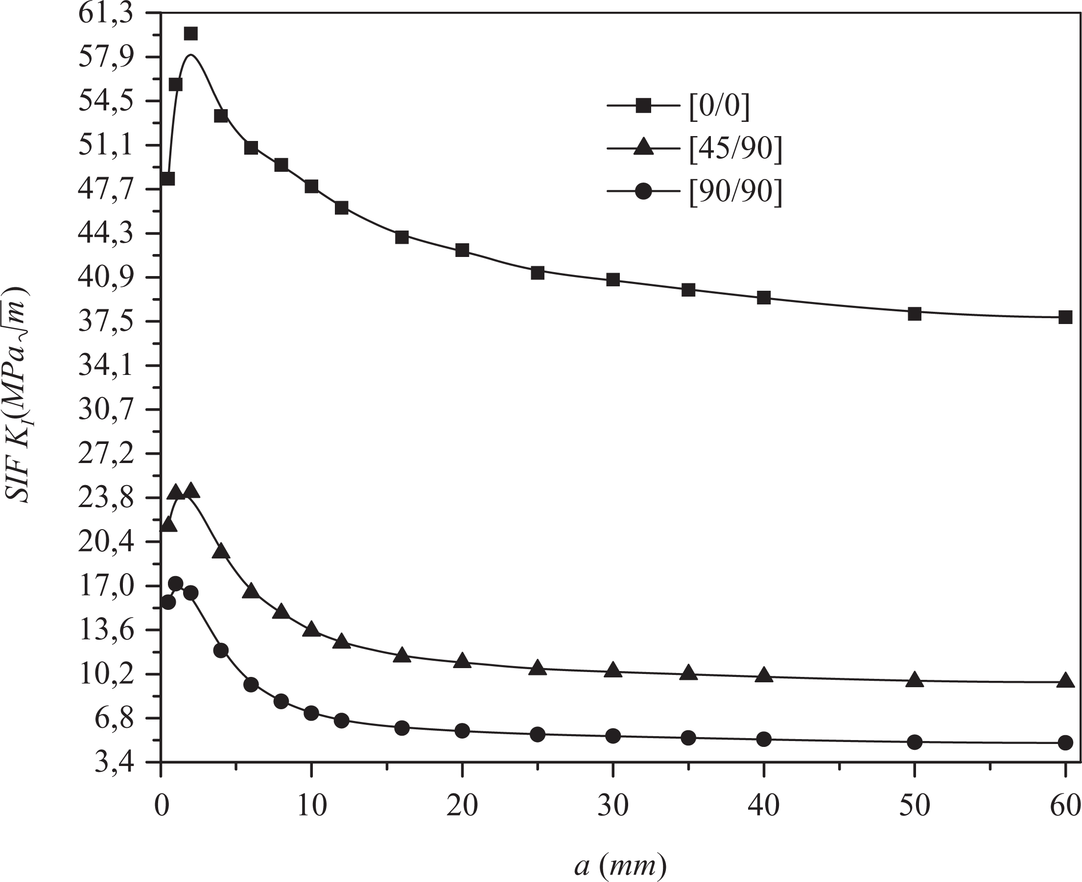
Variation of the stress intensity factor versus the crack length.
When the crack propagates from the notch, it receives a driving force of the surrounding stress field leading to an increase in the SIF to a peak corresponding to a crack length a = 2 mm, then it decreases gradually toward an asymptotic value. The reduction in the SIF influences directly the kinetics of the crack.
The SIF decreases proportionally with the length of the crack emanating from the side semicircular notch. The maximum reduction in the SIF KI amounts to 60 and 70%, respectively, for fiber orientations at (45/90) and (90/90) compared with the orientation (0/0).
Conclusion
This article investigates the influence of the fiber orientation of a laminate composite material in the presence of a semicircular notch on the SCF and the SIF. The adhesive shear modulus, the thickness of the adhesive and the thickness of laminate layer play a key role in the stress concentrations distribution in the vicinities of the notch and the crack tip. The following conclusions can be drawn:
The reinforcement by composite reduces considerably the stress concentration, which involves a delayed action of the initiation of a crack, and contributes to the increase in the service life of the structure.
The SCF at notch root is not affected by the adhesive layer properties.
The stress concentrations at the notch root are larger in the layer where the orientation of fibers is parallel to the load applied and smaller when the fibers are perpendicular.
The SCF Kt increases proportionally with the decrease of composite ply thickness for any fiber orientation. The increase is marked much more when the thickness tends to be a zero value, indicating a necessary optimization of ply thickness.
A bad fiber orientation of the laminate relative to the crack propagation influences the usefulness of the assembly.
For small lengths of crack emanating from the notch, the SIF is large but decreases with the increase in the crack size up to an asymptotic value.
The SIF of the crack emanating from notch decreases when the angle of the ply orientation increases. An opposite effect occurs at the notch root as the SCF increases.
Footnotes
Acknowledgements
The Authors extend their appreciation to the Deanship of Scientific Research at King Saud University for funding the work through the research group No. RGP-VPP-035.
Funding
This work was funded by Prof M. S. E. Seddiki Rector of University of Mostaganem.